In this SECTION most of the information presented so far is combined and used to calculate various characteristics of AC circuits. Graphic methods can be used for many of the calculations, but, as previously shown, algebraic methods are more accurate and more convenient, so greater use is made of them.
SECTION 1 introduced several basic properties of resistance and reactance which form the basis of the calculations presented. In a pure inductance the current lags the voltage by 90°; in a pure capacitance the current leads the voltage by 90°; and in a pure resistance current and voltage are in phase with each other. Of course, no component is perfect; a resistor, for example, also has some inductance, and even some capacitance.
Similarly, inductors have resistance and capacitance, etc. These calculations are based on the lumping of R, L, and C under their respective categories in a given problem. As an example, if R and L are connected in series, the R in the problem is considered to be the total resistance in the resistors, inductors, and even the wires.
This SECTION presents series circuits first, then parallel circuits, and finally complex circuits (which are combinations of series and parallel arrangements). You will see that there are several different methods for solving some of the problems, for example, straight series and parallel circuits. In other cases,
Vector Algebra must be relied on so that all facets of the problem are considered. Phase relations must be included in virtually all of the calculations if correct results are to be obtained. In this SECTION vectors are used to represent magnitude and phase, and, therefore, they could be called phasors because of their usage.
In order to simplify calculations, it will be assumed that R, XL, and Xe are known. If L or C is given instead, the reactance can be calculated and then included with the problem. To further simplify the problems, small numbers are used for resistance, reactance, and voltage, and they are stated in basic units. The same ideas apply to larger numbers, but working with them is more cumbersome, offering a greater chance for error.
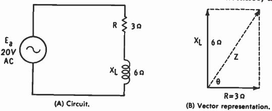
Fig. 5-1. R and L in series. (A) Circuit. (B) Vector representation.
SERIES CIRCUITS
There are certain characteristics of series circuits which apply for both DC and AC, and these form the basis for most of our calculations of series-circuit quantities.
1. The current is the same at any point in the circuit.
2. The voltage drop across each component is equal to the current times the resistance (or reactance) of that component.
3. The sum of the individual voltages is equal to the applied voltage, although for AC the vector sum is implied.
4. The total circuit opposition is the sum of all the separate oppositions, although for AC the vector sum is implied.
5. Ohm's law applies to both DC and AC circuits.
R and L in Series As an example of an RL series circuit, Fig. 5-1A is considered. R is the resistance, XL is the inductive reactance, and E. is the applied voltage. Current through the resistor is in phase with the voltage drop across it, but in the inductance the cur rent lags the voltage drop by 90°. Current is the same through both components so that the separate voltage drops are 90° out of phase with each other. The circuit current lags the applied . voltage by some angle between 0° and 90° because of the combined action of the two components.
A vector representation of the circuit oppositions is given in Fig. 5-1B. Resistance is plotted on the real axis (X), and reactance on the imaginary axis (Y). The reactance is inductive so it is plotted upward, giving a complex expression of 3 + j6 ohms. It is standard to plot XL upward and Xc downward, the reason for which becomes more apparent from the vector representation of current and voltage (shown later). The diagonal of the parallelogram in Fig. 5-1B represents the resultant of resistance and inductive reactance, which is impedance Z. To find the impedance, the resultant can be measured and calculated from the scale of the graph. A more accurate method of calculation, however, is the Pythagorean formula:
Z = v R2 +xt2 = v 32 ± 62 = V- 43 = 6.71 ohms
Calculations in this SECTION are rounded off so as not to complicate the problems with long and tedious calculations involving many decimal places. Also, in the use of the trig tables no attempt at interpolation is made. Angles are read to the closest tenth of a degree. For these reasons there are slight discrepancies between similar answers obtained by different methods of calculation.
The phase angle (0) must be calculated separately because it is not included in the Pythagorean formula:
0 = arc tan - 6 = arc tan 2 = 63.4° 3
Therefore, impedance can be stated in two ways, as 6.71/63.4° ohms in polar form or as 3 + j6 ohms in rectangular form. Strict rules of mathematical writing may demand that parentheses be used with the rectangular form as (3 + j6)
ohms since the unit applies to both terms. However, it is impossible to add ohms to any other quantity so it has become more or less conventional to omit the parentheses, as done previously. Knowing the impedance of the circuit and the applied voltage, a simple Ohm's law calculation can be used to determine circuit current:
E 20 I = --=-= 2.98 amperes
Performing the same calculation in polar form gives this result:
E 20/0° I - E. Z - 6.71/63.4° - 2.98/-63.4 amperes
The negative angle is listed with respect to the applied voltage (assuming it to be at 0° ). This is logical because in an inductive circuit the current lags the voltage. Even so, it is customary to use current as the reference in series circuits be cause it is the same through all parts of the circuit. This means that a more standard representation is that of Fig. 5-2A, which is a graphic presentation of the phase conditions illustrated in Fig. 5-2B. And in the previous problem current would be assumed to be at 0° and applied voltage at +63.4°. Bear in mind though that these vectors represent phase and could be called phasors. The individual phases are continually changing because of the changing nature of the applied AC, but the phase difference is constant. Regardless of the part of the cycle that is considered, in every case the current is lagging the applied voltage by the phase angle. The vectors of Fig. 5-2A could have been drawn at any angles as long as voltage was shown to be 63.4° counterclockwise from the current.
Considering one circuit parameter at 0° simplifies the calculations and has come to be conventional.
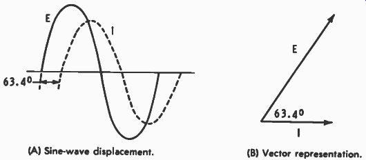
Fig. 5-2. Current and voltage with a phase difference of 63.4°. (A) Sine-wave
displacement. (B) Vector representation.
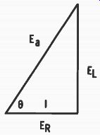
Fig. 5-3. Vector representation of voltages in Fig. 5-1A.
Voltage drop across a separate component can be calculated by Ohm's law, multiplying the current by the opposition offered by that component. In the same problem:
ER = I X R = 2.98 x 3 = 8.94 volts
EL = I x XL = 2.98 x 6 = 17.88 volts
Notice that the two voltages add up to an amount greater than the applied voltage because of the 90° phase difference be tween the two voltages. Fig. 5-3 is a vectorial representation of the voltages involved. Current and voltage across the resistor are plotted at 0°; the reactive voltage is plotted at 90° because it leads the current (or current lags) by 90°. Applied voltage is the vector sum of the two individual voltages and is the diagonal as shown. The phase angle is that already calculated and is between 0° and 90°, depending on the relative values of resistance and reactance.
This triangle is similar to that of Fig. 5-1B. The sides are not the same lengths because the voltages are not the same as the circuit oppositions. But the relationships between the sides are the same, with θ being 63.4°. From Fig. 5-3: E. = - V ER' + EL' = V (8.94) 2 ± (17.88) 2 = 20 volts
And the phase angle could also have been determined by:
EL 0 = arc tan -,- 1 = arc tan 17'88 - 63.4° Edit 8.94
Triangles are said to be similar when their angular distributions are the same, therefore, they have the same general shape.
In both the impedance and the voltage triangles the angles are 90°, 63.4°, and 26.6°, indicating that the comparable sides have the same length relationships in both cases.
Power in each of the components can be calculated from the current or from the voltage with the same results:
PR = I2R = 2.98' x 3 = 26.64 watts P, = I'XL -= 2.98' x 6 = 53.28 vars
If voltage were used, the comparable formulas would be E2/R and E2/XL. For reactive power the quantity can also be stated in watts, but it is conventional to state it in vars (volt amperes reactive) to distinguish it from resistive or other types of power. That power in the resistance is called true power; it is actually dissipated, or used. Reactive power is not used or dissipated because the voltage and current are 90° out of phase. This means that all of the power furnished to a circuit is not actually used, but some of it is returned to the supply line.
As previously shown, the true (resistive) power ( PT) in the circuit under consideration is 26.64 watts. Line voltage times line current, however, gives a greater amount:
Pa = Ea x I = 20(2.98) = 59.6 volt-amperes
This is the apparent power (Pa), the power that apparently is being used. The unit is volt-amperes and is used to distinguish it from true power which is expressed in watts.
Power factor (PF) is the ratio of true to apparent power and expresses the fractional part of the total which is actually being used. In the same problem: PF = P' = 26' 64 - .447 Pa 59.6
It is usually expressed as a decimal fraction, but it could also be expressed as a percentage, 44.7% in this example. This means that 44.7% of the apparent power is being dissipated.
For a purely reactive circuit the power factor is zero; no power is used. For a purely resistive circuit the power factor is one (or 100% ) ; all of the power that is supplied is actually used.
For combination circuits the power factor is always between zero and one.
A power factor can also be expressed as the cosine of the phase angle, as is evident from reference to Fig. 5-7, which is described with reference to RCL circuits: PF = cos θ = cos 63.4 = .4478 The slight difference is due to estimating arc tan 2 earlier in the discussion and in rounding off the results of the power calculation.
The power factor, for series circuits only, can also be calculated as follows:
R 3 PF = = - .4471 Z 6.71
In summary, there are three methods of calculating the power factor of a series circuit: PF = = cos θ - R P„
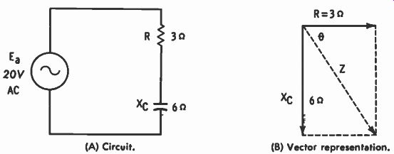
Fig. 5-4. R and C in series. (A) Circuit. (B) Vector representation.
The circuit under consideration is inductive so the current lags the applied voltage. Therefore the power factor can be referred to as being inductive, or lagging.
R and C in Series To simplify the coverage of RC series circuits the same values as used with the RL examples are used. The RC circuit is that of Fig. 5-4A and the impedance vectors are labeled Fig. 5-4B. In rectangular form the impedance is 3 - j6 ohms, but the absolute value of impedance is Z v R2 ± xe2 v 32 + 62 = V 45 = 6.71 ohms The phase angle has the same magnitude as in the previous circuit, but it is in the opposite direction.
θ = arc tan - - 36 -= arc tan (-2) = -63.4°
An angle of -116.6' is also the arc tangent of -2, but the phase angle is always 90° or less in these types of circuits-the obtuse angle is not considered. Impedance, then, can be ex pressed in rectangular form as 3 - j6 ohms or in polar form as 6.71/-63.4° ohms. Current is calculated by Ea/Z just as with the RL circuit, and the values are the same. In fact all the calculations for the RC circuit are the same as for the RL circuit, except for the angle. However, the magnitudes of angles are the same; only the signs are different.
With current as the reference, the voltage of the RC circuit is at -63.4°, lagging the current by that amount of angular displacement. So rather than repeat all the calculations, the various values for the circuit of Fig. 5-4A are as follows:
Z = 6.71/-63.4° ohms I = 2.98M3.4° amperes ER = 8.94 volts
= 17.88 volts PR = 26.64 watts
= 53.28 vars P. = 59.6 volt-amperes PF = .447 (leading)
This means that series-circuit calculations can be simplified because the same relationships hold for both RL and RC circuits; i.e., as long as the direction of angle is considered when ever necessary.
R, C, and L in Series
In a circuit containing all three circuit oppositions, R, X,,, and Xc ., the two reactances effectively oppose each other. The circuit can act inductively or capacitively, depending on whichever reactance is larger. So the resultant circuit is composed of resistance and the difference between the two reactances. Such a circuit is shown in Fig. 5-5A where the rectangular form for impedance is:
Z = R + jXL - = 5 j7 - j3 = 5 + j4 ohms
The resultant circuit for calculation purposes is that of Fig. 5-5B. Impedance, current, phase angle, and power factor are calculated as though that were the circuit.
Z = V R 2 + ( XL - XC) = 52 ± (7 _ 3)2 = 52 + 42
= V 25 + 16 = V 41 = 6.4 ohms E 20 I = = - = 3.12 amperes Z 6.4 θ = arc tan - 4 = arc tan .8 = 38.7° 5 PF = - R = - 5 = 7812 Z 6.4 PF = cos θ = cos 38.7° = .7804
The small discrepancy occurred because, from the tangent table, the actual phase angle is somewhat less than 38.7°. But that is the closest value in the table. If the angle were slightly smaller than that shown, the cosine of that angle would be slightly larger.
Individual voltage drops and power in each of the components must be calculated from the actual circuit (Fig. 5-5A).
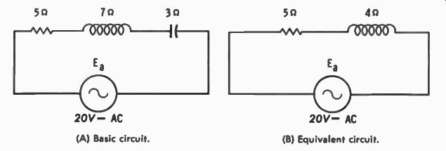
Fig. 5-5. An RCL circuit and its equivalent. (B) Equivalent circuit. (A) Basic
circuit.

Fig. 5-6. Voltages of Fig. 5-5 plotted as vectors. (A) The three individual
voltages. (B) Resultant voltages.
The combined voltages and powers, however, resolve to the simplified (Fig. 5-5B) because of the direct opposition of L and C in the circuit.
ER = I X R = 3.12(5) = 15.6 volts EL = I x XL = 3.12 (7) = 21.84 volts Ec = I x X,, = 3.12(3) = 9.36 volts E. = EL - Ec = 21.84 - 9.36 = 12.48 volts
The total reactive voltage is the difference between EL and Ec, which is 12.48 volts. All three voltages are plotted as vectors (phasors) in Fig. 5-6A, but the resultant voltages are shown in Fig. 5-6B. The diagonal in this figure is the applied voltage, which can be determined from: E. = V E 2 + ER2= V 15.62 + 12.482 = V 243.36 + 155.75 = V 399.11 = 19.98 volts which is very close to the 20-volt value given as applied voltage in the original problem.
Powers are solved similarly:
PR = PR = ( 3.12) 2(5) = 9.73 (5) = 48.65 watts PL = I 2XL = ( 3.12) 2(7) = 9.73(7) = 68.11 vars Pc = I 2Xc = (3.12) 2(3) = 9.73 (3) = 29.19 vars Px = P1. - Pc = 68.11 - 29.19 = 38.92 vars
The total reactive power in the circuit is 38.92 vars, and a triangle can be set up from true power (PR), reactive power (Ps), and apparent power (P.). Refer to the triangle in Fig. 5-7. This triangle is similar to the impedance triangle because the powers are obtained by multiplying the current squared times the number of ohms represented by each side of the impedance triangle. Therefore θ is also the same value, as is also the power factor.
P. = E. X I ----- 20 x 3.12 = 62.4 volt-amperes PF = P` = 48' 65 - .78 P. 62.4
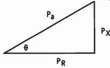
Fig. 5-7. Triangle showing Pµ, Px, and Ps.
.....which is approximately the same as calculated by other methods.
Reactive power is not a major consideration in most requirements; therefore it will not be calculated in the remaining problems of this SECTION. If required in a particular problem, however, it can be calculated as done in this example. And in all cases:
Pa = v'pR2 px2
Three triangles are possible with series circuits-those rep resenting impedance, voltage, and power. All are similar, al though the side lengths are different in each triangle. If XL is larger than Xc in a series circuit, then EL is larger than Ec, and the circuit is inductive by an amount that depends on the relative circuit values. If X,. is larger than XL, then Ec is larger than EL, and the circuit is capacitive. Note that the straight series circuit can be calculated without using Vector Algebra, although it can be used as shown in some of the calculations. This is also true of straight-parallel arrangements which are described next. Vector Algebra finds its greatest application in combination or complex circuits, which are also covered in this SECTION. Its advantage is that the angles are carried with the problem along with the absolute quantities.
This will become evident as complex circuit examples are presented.
PARALLEL CIRCUITS
There are certain characteristics of parallel circuits that hold in all cases, and these should be considered in calculations involving parallel circuits.
1. Voltage is the same across each of the parallel branches.
2. Current through each branch is determined by voltage divided by the opposition (R or X) of that branch.
3. The sum of the currents of the individual branches is the total circuit current. For AC the vector sum is implied.
4. Ohm's law applies to each branch of the circuit, as well as to the total circuit.
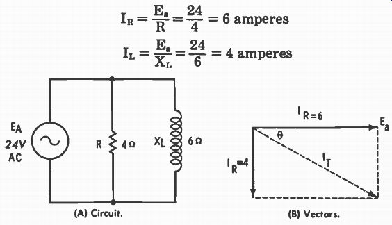
Fig. 5-8. Circuit and vectors of R and L in parallel. (A) Circuit. (B) Vectors.
RL in Parallel
In Fig. 5-8A a resistance of 4 ohms is connected in parallel with an inductive reactance of 6 ohms, with 24 volts applied.
One of the easiest ways to calculate parallel circuit impedance is to use what is known as the current method. First the individual and then the total currents are determined, then the total current is divided into the applied voltage to calculate impedance. The advantage of this method is that only Ohm's law and the Pythagorean formula are needed. No special formulas are needed, although there are some that can be used.
Ea 24 - = 6 amperes R 4 E 24 = - = 4 amperes XL 6
The current through the resistance is in phase with the applied voltage; the current through the inductance lags the voltage by 90°, assuming pure inductance (no resistance). Vector representation of these currents is shown in Fig. 5-8B where I T is the total current. The total current lags the applied voltage by phase angle θ. This could be determined graphically, but an algebraic solution is more definite:
I T = NrIR2 + 1 1 , 2 = V 6 2 + 4 2 = V 36 + 16 = -\/ 52
= 7.21 amperes I, 4
0 = arc tan = arc tan - = 33.7° 6
The I T vector is below the 0° reference so 0 is a negative angle. Total current, in polar form, is 7.21/-33.7° amperes.
Impedance can be determined by Ohm's law, using polar notation and considering the voltage as the reference:
E. 24/0° Z I7.21/-33.7° - - = 3.33/33.7° ohms T
The positive impedance angle is indicative of an inductive circuit, which we already know in this problem. There is no capacitance. But the sign of the impedance angle is important for circuits containing both L and C and in which the resultant could be either inductive or capacitive, depending on relative values. This is especially true for complex circuits in which a visual examination cannot alone determine the type of reactance that predominates.
Note that the Pythagorean formula cannot be used for circuit oppositions connected in parallel. The arrangement Z = V R 2 ± X1,2 holds only for series circuits. With parallel circuits the currents are added vectorially, not the circuit oppositions.
Phase angle has already been calculated so that the power factor can be calculated from it:
PF = cos 0 = cos 33.7° = .8320 Cos 33.7° is the same value as cos -33.7° so either angle could have been used. We know, however, that it is a lagging power factor since the current lags the applied voltage. True power is that in the resistance, just as in series circuits, and can be calculated by any one of the three power formulas.
PR = Ea X I n = 24 x 6 = 144 watts I 2R or E2/R could have been used with the same results.
Apparent power is the applied voltage times the total current: Pa = Ea X I T = 24 x 7.21 = 173.04 volt-amperes PF = Pt = 144' 173.04 =.8321 The results are very close to those obtained by determining the cosine of the phase angle. Also: PF = Z = 3.33 = .8325 R 4 Note the difference here from the way that the power factor was calculated in series circuits. For series arrangements PF = R/Z, but cos θ and P,/P„ hold for all types of circuits.
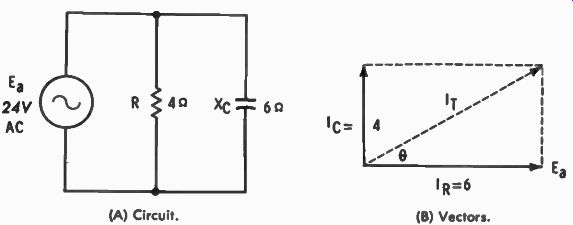
Fig. 5-9. Parallel-connected RC circuit. (A) Circuit. (B) Vectors.
RC in Parallel
Fig. 5-9A is used as an example of a parallel-connected RC circuit. This is the same circuit as Fig. 5-8A, except that XL has been changed to Xe with the same numerical value. This simplifies the calculations for this part of the SECTION since the absolute values for the various circuit characteristics are the same:
Ea 24 I R = = - - 4 - = 6 amperes E 24 l e = X - 6 = 4 amperes e Current through R is in phase with the applied voltage, but the current through Xe leads the applied voltage by 90°, assuming pure capacitance (no resistance). Vector representation of these currents is shown in Fig. 5-9B. I T is the vector sum of the individual currents; it leads the applied voltage by phase angle θ. I T = V I R2 I r2 = V 62 + e = vs6 + 16 = N/ 52
-= 7.21 amperes θ = arc tan = arc tan - 4 = 33.7° l it 6
The I T vector is above the 0° reference so that the phase angle is positive, and total current can be expressed as: I T -= 7.21/33.7° amperes E 24/0' Z = = 721/33.7° = 3.33/-33.7° ohms I T . The negative impedance angle is indicative of a capacitive circuit; conversion to rectangular form would show R - j PF = cos θ = cos 33.7° = .8320 The result is the same as calculated for the comparable RL parallel circuit, but in the RC arrangement the power factor is leading. This is true because the current leads the applied voltage, as is normal in a capacitive circuit.
True and apparent powers are also calculated the same as in the previous circuit: PR = E,, X I R = 24 x 6 = 144 watts Pa := Ea X I T = 24 x 7.21 = 173.04 volt amperes pF _ .. = P 144 Pa 173.04 - . 8321 PF = Z/R could also have been used with similar results.
Note again that the absolute values of both circuits are the same, even the magnitude of the phase angle. The only difference is the sign of the angle, with total current lagging in the RL circuit and leading in the RC circuit.
RCL in Parallel
In a circuit including all three types of circuit opposition the two reactances effectively oppose each other in determining total current. The total current can be either inductive or capacitive, depending on the relative values of the two reactances.
Fig. 5-10 is used as an illustration of such a circuit. The applied voltage is common to all three branches so that it is used as the 0° reference in the calculations:
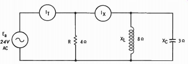
Fig. 5-10. Parallel-connected RCL circuit.
, = = = 6 amperes = (6/0°) = 6 T
- - - 3 amperes = (3/-90°) = -j3 8
E. 24 = re.= - e- = 8 amperes = (81+90°) = +j8
Vector representation of these currents is illustrated in Fig. 5-11A with the resultant of these currents in Fig. 5-11B. I, leads E. by 90°, and I. lags by 90°. Thus, the vector sum of the reactive currents is 8 - 3, or 5 amperes of capacitive current.
This means that the I x meter in Fig. 5-10 reads 5 amperes and that current leads the voltage by 90°; total circuit current is 6 + j5 amperes. As the two currents are at 90° with respect to each other, they can be added by the Pythagorean formula: I T = V 6 2 + 5 2 = V 36 + 25 = V-6 - 1 = 7.81 amperes θ = arc tan - 5 = arc tan .8333 = 39.8° 6 I T = 7.81/39.8° amperes E 24/0° Z - - I T 7.81/39.8° - 3.07L-39.8° ohms The impedance angle is negative, which is indicative of a capacitive circuit and which agrees with the previous calculations that showed capacitive current to be greater than inductive current.
Impedance could be solved directly by using Vector Algebra, but it is a longer process with more probable chance of error.
The current method is probably the easier of the two, and therefore it is generally used. However, a vector solution is shown here to illustrate the ideas involved.
First the equivalent of XL and Xc in parallel is determined by the product-over-the-sum method: (ixi) (ixr) X = = J AL-1- J Ac
_24 j = j24 - • - j 5 j -5 (j8) (-j3) _ -j 224 j8 -j 3 j 5
= -j4.8 ohms
Then this X value is combined with R in another product-over the-sum calculation, the result of which is the impedance: Z (R) (jX) _ (4) (-j4.8) _ -j19.2 R + jX - 4 - j4.8 4 - j4.8 19.2/-90° 6.25/50.2° - 3.07/50.2 ohms Results are the same as obtained using the current method.
True power is that amount dissipated in the resistance, just as in same (A) All currents. (B) Resultant.
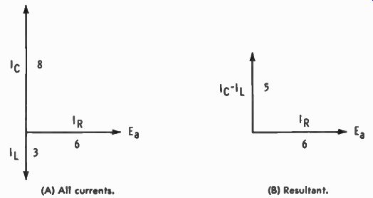
Fig. 5-11. Vector representation of the currents in Fig. 5-10.
other circuits. Apparent power is also calculated in the manner-applied voltage times total current.
P, = Et , X I R = 24 x 6 = 144 watts P. = E. X ' T = 24 X 7.81 = 187.44 volt amperes pF = t = P 144
-7682 1 87.44 .
From the trig table: PF = cos θ = cos 39.8° = .7683 PF = Z/R could also have been used.
It should be remembered that in almost every problem the results vary slightly because of rounding off in the various methods used, and due to approximating the angles from the trig tables. By carrying the various computations to a larger number of decimal places and interpolating with the trig tables, almost exact results can be obtained, regardless of the method and assuming, of course, that a correct method is being used.
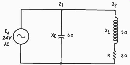
Fig. 5-12. A combination series-parallel circuit.
COMPLEX CIRCUITS
As was previously pointed out, simple series and parallel AC circuits can be handled by Ohm's law and the Pythagorean relationship for almost all the usual types of calculations. Complex numbers are not required, although they can be used if desired. For complex circuits (combinations of series and parallel) Vector Algebra can be used to the greatest advantage.
The circuit of Fig. 5-12 is an example. For convenience of notation, Z, indicates the impedance of the capacitive branch; Z., the combined impedance of the resistance and inductance.
Solution is by the current method, and as will be seen, vector notation is required because of the relationship of the angles.
Z, = 0 - j6 ohms = 6/-90° ohms I, = 0 + j4 amperes = 4/0° amperes Z2 = 8 + j5 ohms = 9.43/32° ohms 1 2 =- 2.15 - j1.35 amperes = 2.54/-32° amperes Total current ( I T) is:
0 + j4 2.15 - j1.35 2.15 + j2.65 amperes
Converting to polar form: I T = 3.41/50.9° amperes E 24 /±(1' Z = a - = 7.04/-50.9 ohms I T 3.41/50.9°
Capacitive current is greater than that through the other branch, so the total circuit is capacitive. Notice that the vector notation was necessary because the phase angle of branch 2 was not 0° nor 90°, but a value between those two limits.
Quantities at 0° or 180° can be combined by simple addition or subtraction; at 90° they can be combined by the Pythagorean formula. For any other angle, however, a graphic or an algebraic solution is necessary, including the angles as definite parts of the problem. This was pointed out in SECTION 3.
Impedance of the same circuit can also be determined by the product-over-the-sum method: Z - '- ZiZo (0 -j6) (8 + j5) -j48 - j 230 T Zi ± Z2 0 - j6 + 8 + j5 8 - j 30 - j48 8 + j _ 240 - j384 + j30 - j 248 = 8 - j 8 + j 64 - j 2
= 288 - 62354 - 4.43 - j5.44 ohms
Conversion to polar form gives: ZT = 7.02/-50.8° ohms
This is very close to the quantity obtained by use of the current method. Power-factor calculations are also close: P, -= 1 2 2 X R = 2.542 x 8 = 51.61 watts P. = E. X I T = 24 x 3.41 = 81.84 volt-amperes PI., _ P, = 51.61 = . 6306 P. 81.84 And from the trig table: PF = cos 6 = cos 50.9° = .6307 Neither R/Z nor Z/R can be used to calculate the power factor because of the complex circuit arrangement. These relationships hold only for straight series and straight parallel circuits, as illustrated previously.
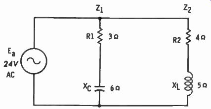
Fig. 5-13. A more complex series-parallel circuit.
A slightly more complex circuit arrangement is that of Fig. 5-13.
The methods of calculation are similar to those used for the previous circuit: Z, = 3 - j6 ohms = 6.71/-63.4° ohms y E. 24/0° Z - 6.71/-63.4° 3.58/63.4° amperes , Z2 = 4 + j5 ohms = 6.4/51.3° ohms E5 24/0° = = 6.4/51.3o-- - 3.75J-51.3° amperes - Z2 Total current is (3.58/63.4° + 3.75/-51.3°) amperes. Converting to rectangular form and adding:
= 3.58/63.4° = 1.60 +j3.20 1 2 = 3.75/-51.3° = 2.34 - j2.93 I T = 3.94 + j.27 = 3.95/3.9° amperes E 24/0° Z = = 3.95/3.9° - 6.08/-3.9° ohms
_ Z Z. (3 - j6) (4 + j5) 12 + j15 - j24 - j 230 Z, + Z2 3 - j6 + 4 + j5 7 - j 42 - j9 7 + j _ 294 + j42 - j63 - j 29 7 - j 7 + j 49 - j 2 303 - j21 50 - 6.06 - j.42 ohms
Conversion to polar form gives: Z, = 6.08/-4° ohms The negative phase angle for impedance is indicative of a capacitive circuit. This is correct even though the current through the inductive branch is greater. Relative values of oppositions and angles combine to determine the total result, which cannot be determined solely by magnitudes.
E. 24/0° I T = Zi• = 6.08/-4° 3.95/4° amperes PF = cos 0 = cos 4° = .9976
Current is leading the voltage so the power factor is leading.
PT = ( I12 X R1) (12 2 X R2)
= (3.582 x 3) + (3.752 X 4)
= 38.45 + 56.25 = 94.7 watts P. = E. X
It = 24 x 3.95 = 94.8 watts P 94 7 .9989 P. 94.8

Fig. 5-14. RCL series circuit.
From cos 0, PF = .9976, a slight difference resulting from rounding off the results of calculations and in not interpolating the trig ratios. The more involved the circuit, the more chances there are for accumulating inaccuracies. The purpose here is to illustrate methods rather than extreme accuracy because the latter requires more time without increasing the understanding of the subject.
The ideas presented here can also be used for circuits that are even more complex than those illustrated. In series circuits the resistances and reactances should be combined so that the impedance can be expressed in a single complex number.
For example, in Fig. 5-14 the total resistance is 13 ohms, inductive reactance is 11 ohms, and capacitive reactance is 9 ohms. Consequently, the total circuit impedance is 13 + j2 ohms.
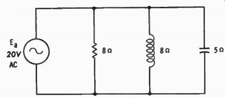
Fig. 5-15. Circuit for Problem 13.
In a circuit consisting of several parallel branches this type of simplification should be performed in each branch before proceeding with the parallel calculations. When more than two branches are involved, any two can be combined, as illustrated previously, and the resultant so obtained combined with other parts of the circuit. For example, if three branches were involved, any two could be solved for a resultant. Then that resultant could be calculated with the third branch to give a total resultant circuit. If four branches were being considered, numbers one and two could be calculated for a resultant, numbers three and four treated likewise, then the two resultants combined for the total arrangement.
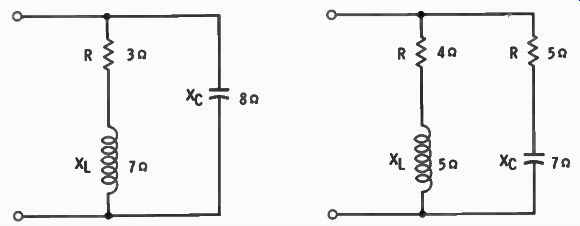
Fig. 5-16. Circuit for Problem 15.
Fig. 5-17. Circuit for Problem 16.
QUIZ
1. A series RL circuit includes 4 ohms of resistance and 5 ohms of inductive reactance. Calculate impedance, phase angle, and power factor of the circuit.
2. If 20 volts are applied to this circuit, what is the current? Is it leading or is it lagging the applied voltage?
3. A series RL circuit has 8 volts across the resistance and 12 volts across the inductance. What is the applied voltage? What is the phase angle?
4. A series RC circuit includes 6 ohms resistance and 9 ohms capacitive reactance. Calculate impedance, phase angle, and power factor of the circuit.
5. If 12 volts are applied to this circuit, what is the current? Is it leading, or is it lagging the applied voltage?
6. Calculate the true power and the apparent power of this same circuit.
7. A series RC circuit has 24 volts applied, and there are 12 volts across the resistor. What is the voltage drop across the capacitor?
8. A series RCL circuit includes 6 ohms of resistance, 8 ohms of capacitive reactance, and 5 ohms of inductive reactance. Express the impedance in both rectangular and polar forms.
9. If 24 volts are applied to this circuit, what is the current and the phase angle? Is the current leading or is it lagging the applied voltage?
10. There are 8 ohms of inductive reactance connected in parallel with 5 ohms of resistance. Calculate the impedance and phase angle of this circuit.
11. If 20 volts are applied to this circuit, calculate the reactive power and the power factor.
12. A parallel RC circuit has an impedance of 3 ohms and a resistance of 5 ohms. Calculate the capacitive reactance.
13. What is the impedance of the circuit of Fig. 5-15?
14. What is the true power and the phase angle of the same circuit? Is the current leading or is it lagging the applied voltage?
15. Calculate the impedance of the circuit of Fig. 5-16. Is this circuit inductive, or is it capacitive?
16. Calculate the impedance of the circuit of Fig. 5-17. What is the phase angle?