The most widely used test instrument in electrical and electronics work is the volt-ohm-milliammeter ( VOM). This instrument is used by electricians, technicians, experimenters, teachers, scientists, engineers, inventors, and students. VOM's find wide application in troubleshooting; electrical maintenance; design; production work; radio, tv, and appliance servicing; and in many other areas. Electronic VOM's or multimeters, including the solid-state, vacuum-tube, integrated-circuit, and digital types, are also widely used. The student or technician usually starts out using a non-electronic VOM but soon adds one or more electronic types to his personal array of instruments.
Since VOM's and the various emm's (electronic multimeters ) are so widely used, it is important for the electronics worker, whether he be student, technician, teacher, engineer, or experimenter, to understand their use, care, maintenance, and principles of operation.
The topics discussed in this guide cover the types of VOM's and emm's most widely used. Detailed discussion of a particular instrument does not necessarily imply that it is the best one or the only one. In cases where an instrument described is not the latest model, a later version will generally be the same except for minor improvements.
However, it is not the main purpose of this guide to discuss particular instruments, but rather to explain the major features common to these instruments. It will tell you what features should be considered before purchasing a new instrument or tell you how you can best use the one you have.
REVIEW OF ELEMENTARY ELECTRICITY
At this point, before beginning with detailed discussions about VOM's, it might be worthwhile to review some of the principles of electricity-especially those principles that are important in understanding VOM's.
You are probably well aware that all matter is composed of molecules, which are made up of atoms. The atoms consist of neutrons, protons, and electrons. The theory that electricity is the flow of electrons through a conductor (such as a wire ) is now pretty well established. Electrons are negative charges of electricity. They are repelled by other negative charges of electricity, and attracted toward positive charges.
Current
A movement of electrons constitutes an electrical current. The number of electrons that move during a given period of time determines just how much current is flowing. Current is measured in amperes. Currents less than 1 ampere are generally measured in milliamperes or microamperes. The conversion between amperes (A), and milliamperes (mA ), and microamperes ( m-A ) is rather simple; 1 ampere equals 1000 milliamperes or 1,000,000 microamperes. To convert from: Amperes to milliamperes, multiply amperes x 1000. Amperes to microamperes, multiply amperes x 1,000,000. Milliamperes to amperes, divide milliamperes by 1000. Milliamperes to microamperes, multiply milliamperes x 1000. Microamperes to amperes, divide microamperes by 1,000,000. Microamperes to milliamperes, divide microamperes by 1000.
Examples: Converting amperes to milliamperes:
0.0001 ampere = 0.0001 X 1000 = 0.1 milliampere
Converting amperes to microamperes :
0.0001 ampere = 0.0001 X 1,000,000 = 100 microamperes
Converting milliamperes to amperes :
0.1 milliampere -7- 1000 = 0.0001 ampere
In practical situations, the units are seldom converted. Instead, the most convenient unit for the amount of current is used. For example, the use of 10 amperes is preferred to the use of 10,000 milliamperes or 10,000,000 microamperes. Similarly, the use of 5 milli amperes is preferred to the use of 0.005 ampere.
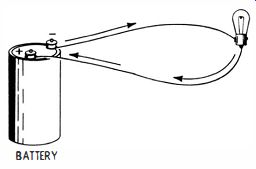
Fig. 1-1. Direct-current circuit.
DC and AC Voltage
Voltage is the energy that causes electrons to move. Usually the source of voltage is a battery or an electric generator. There are two basic kinds of voltage; one is dc voltage, and the other is ac voltage.
Direct-current (dc) voltage causes the electrons to move from the negative side of the voltage source, through one of the two wires required, through the circuit being powered, to the second wire, and back to the positive side of the voltage source. An example of such a dc circuit, a battery providing the power for a lamp bulb, is shown in Fig. 1-1. The movement of electrons is continuous from negative to positive, until the voltage is removed by opening the circuit.
Alternating-current (ac) voltage also causes electrons to move from negative to positive. The difference between ac and dc voltage, however, is that the ac polarity keeps changing at a regular rate, as does the amplitude (magnitude ) of the voltage, while the dc polarity remains constant. At first, one of the two terminals of the ac voltage source may be negative and the other positive, as shown for terminals A and B in Fig. 1-2A; then the one that was negative becomes positive, and the one that was positive becomes negative, as in Fig. 1-2B. Side A starts from zero voltage (point 1 in Fig. 1-2C ), builds up to a maximum positive value (point 2), decreases to zero again (point 3), builds up to the maximum negative value (point 4), falls back to zero (point 5), and rises to maximum positive value (point 6). This sequence is then repeated. The result is that the electrons flow through the wire first in one direction, then stop, flow in the other direction, reverse again, and so on until the circuit is opened.
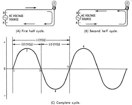
Fig. 1-2. Alternating directions of electron flow through the circuit connected
to ac generator for voltage source.
The number of times per second that a cycle of these variations (zero to positive to zero to negative to zero ) occurs is known as the frequency of the ac voltage. Frequency is sometimes specified in cycles per second (cps) or simply cycles. But the term hertz (abbreviated Hz ) has become the preferred unit for frequency. Therefore, in some cases you may encounter frequency specified in terms of cycles per second; in others it may be specified in terms of hertz.
One hertz is equal to one cycle per second. The value of ac voltage supplied by the utility company to the average home is about 120 volts. and its frequency is usually 60 Hz.
Resistance
The opposition to the flow of electrons through a material is known as resistance. Resistance is low through a wire and through most metals and other conductors. Through nonconductors, or insulators, resistance is high. Resistance is measured in ohms.
Some components in electrical circuits consist of materials designed to have a specific value of resistance; these components, known as resistors, are available in many sizes and values of resistance. The amount of current a resistor must carry usually determines its physical size. Conductors, such as wires, generally have a low resistance-a typical figure would be 1 to 10 ohms for a 100-foot piece of wire.
Relationship of Voltage, Current, and Resistance
In a given electrical circuit, the higher the applied voltage, the greater the amount of current. The lower the voltage, the less the current. Similarly, the greater the resistance, the lower the current, and vice versa.
The relationship of current, voltage, and resistance is given by Ohm's law as : E=IR where, E is the value of the applied voltage, in volts, I is the amount of current, in amperes, flowing in the circuit, R is the value of the resistance, in ohms.
The preceding equation states that the voltage is equal to the current multiplied by the resistance. Thus, if the values of the resistance and the current are known, then their product gives the value of the applied voltage.
If any two of the three quantities are known, the third can be determined. For instance, if the voltage and current are known, the equation for determining the resistance is:
R=E I
Or, resistance is equal to voltage divided by current.
And, if the resistance and the voltage are known, the equation for the current is: 1= E R Or, current is equal to voltage divided by resistance.
Power
The amount of power absorbed in an electrical circuit is usually stated in watts. The power in watts can be found from the equation: P=FR where, P is the power in watts . Or, the power equals the value of the current squared times the resistance.
The power can also be found if the current and voltage are known: P=EI Or, if the voltage and the resistance are known : E? P=1f
In many cases it is important to use an electrical component that is large enough in physical size to dissipate the heat due to the flow of electrical current through the component. Therefore, resistors have a rating in watts. Resistors are commercially available in a variety of wattages. In designing circuits, usually a resistor having twice the wattage rating needed is selected. This is to allow for the possibility that the resistor will operate at a higher temperature than calculations would indicate, due to its location beneath a chassis or inside a cabinet, where the heat is not readily carried away by convection, conduction, or radiation.
Suppose that in a circuit with a voltage source of 100 volts, 0.005 ampere of current is required. The value of the desired resistor is determined from the equation given earlier :
E 100 R
= T
=
0.005
= 20,000 ohms
Next, to determine its rating in watts, use the formula: P = EI = 100 X 0.005 = 0.5 watt Using either formula P = EI or formula P = PR would have given the same answer.
In an open space, a 1/2-watt resistor could be used; but if the circuit is enclosed or if the escape of heat is restricted in any manner, a 1-watt resistor would normally be used.
Characteristics of Alternating Current
The electrical principles and laws just given for dc apply equally to ac. That is, 100 volts ac will cause 0.005 ampere to flow through 20,000 ohms, the same as 100 volts dc will.
It is important, however, to realize the special characteristics of ac. Since ac ranges from zero to maximum positive to maximum negative during each cycle, its average value for each cycle is zero. Of course, as far as effects on an electrical circuit are concerned, this average value of zero does not mean that ac has no effect. When an ac voltage forces electrons through a circuit first in one direction and then in the other, it creates heat or causes other effects, as a dc voltage does. However, the effective value of alternating current is not actually its maximum value. The effective value of ac is related to its maximum value by the factor 0.707, as indicated in the illustration of Fig. 1-3.
E (ac effective ) = E (ac maximum) X 0.707 I (ac effective ) = I (ac maximum) X 0.707
In the other direction, the maximum value is related to the effective value by the factor 1.414.
Maximum = Effective X 1.414
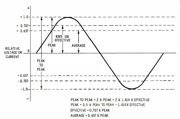
Fig. 1-3. Relationship among peak-to-peak, effective, and average values of
sine-wave alternating voltage or current.
Thus, as an example, the effective value of an ac voltage having a value of 150 volts for its positive and negative peaks can be calculated as: 150 X 0.707 = 106 volts An ac voltage having an effective value of 110 volts has a maximum value of: 110 x 1.414 = 155.5 volts Another term frequently used for maximum values is peak value, and another term commonly used for effective value is rms (root mean-square ) value.
The value of an ac voltage or current is sometimes given in terms of its peak-to-peak value. It is obvious that the peak-to-peak value of a symmetrical ac wave is twice its peak value :
Peak-to-peak value = 2 X peak value = 2 x 1.414 x effective value = 2.828 x effective value
Although the average value for a complete ac cycle is zero, each half cycle of an ac wave has a specific average value. The average value for a half cycle of ac is given by:
Average value = 0.637 x peak value
For many practical purposes, ac voltage or current is referred to as having an average value of 0.637 times its peak value. This is not necessarily restricted to applying to only a half cycle at a time; but for other purposes it is important to keep in mind that the average value of an ac sine-wave voltage or current is zero. This will become apparent later when meter movements are discussed.
QUESTIONS
1. If a sine-wave voltage has a peak value of 150 volts, what is the average value for a half cycle?
2. What is the average value of a full cycle of ac voltage?
3. What is the effective, or RMS, value of an ac voltage that has a peak value of 440 volts?
4. What are electrons? Briefly describe their action in an electric circuit.
5. What constitutes an electric current?
6. Describe the relationship between the following: amperes and milliamperes; microamperes and amperes.
7. Convert 50 milliamperes to amperes; convert 0.00005 ampere to microamperes.
8. What causes the movement of electrons in an electric circuit?
9. Name two sources of voltage.
10. Describe the direction of movement of electrons in a dc circuit supplied by a battery.
11 . Describe the movement of electrons in an ac circuit.
12. What term other than "cycles per second" is used in designating frequency?
13. What is the usual power-line frequency supplied by electric utilities?
14. What name is given to the opposition to the flow of electrons in a material, and in what units is it measured?
15. What is Ohm's law?
16. What form of Ohm's law is used if the unknown quantity is (a) current, or (b) resistance?
17. Determine the resistance of a circuit in which 20 volts causes a current of 80 milliamperes.
18. How much current will there be in a circuit having 25 ohms of resistance if 100 volts is applied to the circuit?
19. How much voltage is required to cause 3 amperes to flow through 60 ohms?
20. Calculate the power in a circuit in which 50 volts is applied and 4 amperes is flowing.
21. Determine the peak ac voltage if the rms value is 150 volts.
22. If the peak value of a sine wave is 125 volts, what is the peak-to-peak value?
Also see: Industrial Electronics (in the early 1960s)