WHAT A VOM CAN DO
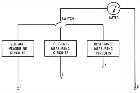
Fig. 2-1 . Basic plan of a VOM.
The designers and manufacturers of VOM's try to make them as versatile and convenient to use as possible. The VOM is a single package instrument with which voltage, current, and resistance can be measured. The ease with which the instrument can be used is usually very important. Also important are the accuracy of the instrument and the ranges of measurement of which it is capable.
The basic design of the VOM is shown in Fig. 2-1 . The meter is the major part of the VOM. The pointer of the meter indicates the value of the voltage, current, or resistance being measured. The voltage-measuring section provides for both ac and dc voltage measurement over any one of several ranges. The resistance-measuring circuit has several ranges of measurement. In Fig. 2-1, terminal C is common for all measurements; the unknown voltage is connected between E and C, the unknown current between I and C, and the unknown resistance between R and C. Generally, a VOM can measure voltages up to 5000 or 6000 volts ac or dc, up to 5, 10, or 15 amperes of current, and up to 1 to 10 megohms of resistance. With some VOM's it is also possible to measure decibels and power.
The basic components of the VOM, as shown in Fig. 2-2, are a meter; test leads; a function switch; and voltage-, current-, and resistance-measuring circuits.
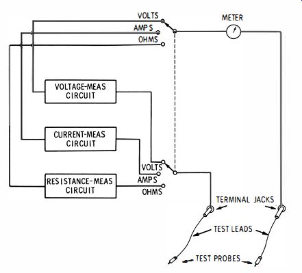
Fig. 2-2. Basic components of the VOM.
BASIC VOM SYSTEM
In some VOM's the switch is not included-in this case, it is necessary to move one of the test leads each time a different function is to be performed by the meter. In Fig. 2-2, if there were no switch, the right-hand test lead would be left where it is at all times and the left-hand lead would be plugged into a jack connected to the resistance-, current-, or voltage-measuring circuit, as desired. Most VOM's do include the function switch, which is the reason for showing it in the figure. Many VOM's include both a function switch and a range switch. The range switch is used for selecting that scale on the VOM that will provide the most convenient-to-read indication for the value of current, voltage, or resistance being measured. An example of a VOM having both a function switch and a range switch is shown in Fig. 2-3.
Meter of the VOM
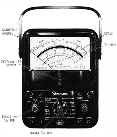
Fig. 2·3. Simpson Model 260 VOM.
To understand the VOM, it is necessary to understand its components. The first one we will consider is the meter, or meter movement. The meter includes a scale and a pointer, or indicator, both attached to a mechanism called a movement. When the VOM is not being used, the pointer remains at the 0 side of the calibrated scale of the meter as in Fig. 2-3. When current flows through the movement, the pointer moves to some position and remains there, if the flow of current is steady, until the current changes in value. Just how much the pointer is moved, or deflected, depends on how much current is flowing through the movement.
It should be kept in mind that whether voltage, current, or resistance is being measured, it is always current that deflects the pointer.
Principle of the Meter Movement
The type of meter movement used in most VOM's is known as the d'Arsonval movement. This movement includes a permanent magnet and a coil to which a pointer is attached. The pointer rotates in the field of the magnet when current passes through the turns of the coil. The principle of the d'Arsonval movement is shown in Fig. 2-4.
The coil is wound about a soft-iron core, or armature. The current to be measured flows through the coil, setting up a magnetic field around the coil, which opposes the field of the magnet. The coil is rotated clockwise by these repelling fields, pulling against a spring which, when no current is passing through the coil, holds the pointer at zero on the calibrated scale. The greater the current, the greater the force turning the coil.
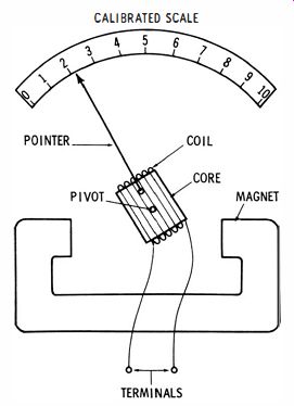
Fig. 2·4. Principle of the d'Arsonval meter movement.
The basic construction of the d' Arsonval movement is shown more clearly in Fig. 2-5. Pole pieces on the permanent magnet decrease the magnetic gap between the magnet and the coil core.
Spiral springs hold the pointer, which is fastened to the coil, at zero when no current is flowing. The core of the coil does not rotate; it is stationary in order to keep the pointer assembly as lightweight as possible. The pivot usually rides in jewel bearings to reduce friction.
Since about 1960, many d'Arsonval movements employ taut-band suspension. This is a design feature that affords greater sensitivity in a meter movement; that is, it allows full-scale deflection with a lower value of current. In taut-band suspension, shown in Fig. 2-6, the pointer is suspended by a band which is a short, very thin, narrow strip of special alloy tightly suspended on special spring terminals. The torsion action of taut-band suspension makes the spiral spring unnecessary.
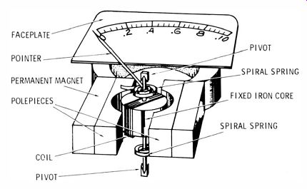
Fig. 2-5. Construction details of the d'Arsonval movement.
When current flows through the meter movement, the suspension band is twisted in proportion to the amount of current. When the current again becomes zero or is decreased, the pointer moves to zero or to the left. The taut-band suspension feature provides the advantage of greater sensitivity, as already mentioned, and also greater resistance to damage from both electrical overload and mechanical shock. It also responds more reliably to different frequencies. The taut-band suspension has no bearings, jewels, or spiral springs; thus, there is extremely little friction which makes possible its great sensitivity.
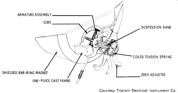
Fig. 2-6. Principle of taut-band suspension movement. Courtesy Triplett Electrical
Instrument Co.
Meter-Movement Precautions
If a meter movement becomes defective, it is usually wise to return it to the manufacturer for repair, or even to replace the movement completely without attempting repair. It is seldom possible for anyone other than a specialist to repair a meter movement properly. Many technicians have learned this the hard way. The typical meter movement is a precision assembly and includes the motor portion which is comprised of the coil, core, jewels, spiral springs, and pointer. The zero-adjuster arm, which is usually accessible from outside the meter case, is the only adjustment that the user should make. It is usually set by turning an eccentric screw on the outside of the meter case so that the pointer indicates zero when no current is flowing through the meter.
Meters are designed for various values of full-scale sensitivity.
The full-scale sensitivity of a meter means the value of current that will cause the meter to deflect to its maximum indicated value. For example, 50 microamperes (0.00005 ampere ) is the value that will deflect the pointer of a moderately sensitive meter to full scale.
If this 50-microampere current flows through the meter when a 250 millivolt voltage is applied to the meter terminals, we can calculate the resistance (R) of the meter movement as follows:
The less current required to deflect a meter full scale, the more sensitive the meter is said to be. Some meter movements will deflect full scale with much less than 50 microamperes ; many require a higher current.
(A) Circuit to deflect meter half scale.
(B) Shunt added to extend range.
(C) Switch system for selecting one of several shunts.
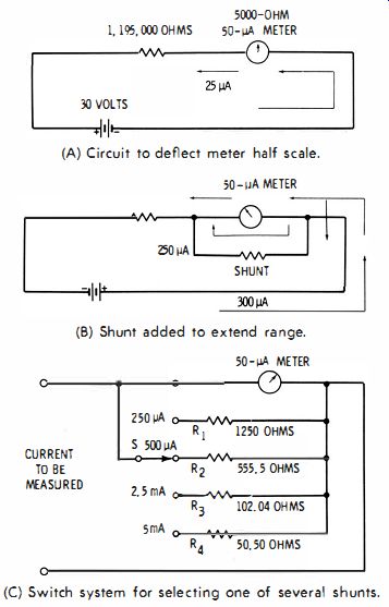
Fig. 2-7. Method of using meter for current measurements.
CURRENT-MEASURING CIRCUIT
It is possible to measure current in a circuit by using only a meter movement if the amount of current flowing does not exceed the rated current of the meter movement. To illustrate, a 50-microampere meter in the circuit of Fig. 2-7 A will be deflected to half scale, Thirty volts applied to 1,200,000 ohms (the 1,195,000-ohm resistor and the 5000 ohms of the meter movement ) causes 25 microamperes to flow through the meter. This is expressed as:
If the battery should be reduced to 15 volts, the meter will be deflected to % of full scale; if it is reduced to 7.5 volts, the meter will deflect to 1fs of its full-scale reading. This process can be continued until the voltage applied will become so low that the movement of the pointer will no longer be discernible, The lowest voltage at which the movement of the meter pointer is significant will be the lower limit of usefulness, The upper limit of usefulness of the meter is, of course, the point where the battery voltage exceeds 60 volts, since beyond this voltage level the current flowing in the circuit will exceed the maximum rating of the meter. Permitting too much current to flow through a meter can cause the coil to burn out or can otherwise damage the meter.
The meter in the circuit of Fig, 2-7 A can be used to measure currents greater than 50 microamperes, To do this, a shunt, or parallel path, is provided around the meter to carry a known portion of the current so that the current through the meter is 50 microamperes or less, This shunt is a resistor, as shown in Fig, 2-7B, with a value that must be accurately selected, For example, if a shunt of 1000 ohms is placed across the meter (Fig, 2-7B ), five times as much current will pass through the shunt as will pass through the meter, since the resistance of the meter is 5000 ohms. Thus, if the meter is reading full scale, a 50-microampere current is going through the meter; 50 X 5, or 250, microamperes is going through the shunt; and the total current is 300 microamperes. Similarly, if the shunt has a value that is 1/50 of the meter value, or 100 ohms, the current through the shunt will be 50 x 50, or 2500 microamperes at full scale, and the total circuit current will be 2SS0 microamperes.
In an actual VOM, any one of several shunts can be switched into the current-measuring circuit, as shown in Fig. 2-7C. This is basically the scheme used in the VOM that you might be using now or in the future. The selection of values of 1250 ohms for shunt R1, 555.5 ohms for R2, 102.04 ohms for R3, and 50.5 ohms for R4, provides additional ranges of 0 to 250 microamperes, 0 to 500 microamperes, 0 to 2.5 milliamperes, and 0 to 5.0 milliamperes, respectively. In many practical VOM's, the shunt-switching arrangement makes it possible to measure dc currents as high as 10, 12, or 15 amperes or more. For these higher ranges, the shunts are pieces of wire or strap with resistances that are accurately selected.
DC VOLTAGE-MEASURING CIRCUIT
If 250 millivolts is applied to the terminals of a 50-microampere meter movement having a resistance of 5000 ohms, the meter will deflect full scale. The meter could be used by itself to measure voltages up to 2S0 millivolts. If a voltage is applied to the meter terminals and if the pointer deflects to its halfway point, it can be assumed that the voltage has a value of 125 millivolts.
Of course, with a typical VOM it is possible to measure voltages much greater than 250 millivolts. Extending the voltage-measuring capability of a meter movement is made possible by adding a multiplier resistor in series with the meter. In Fig. 2-8A, the multiplier resistor shown has a value of 15,000 ohms. When this is added to the 5000 ohms of the meter, it totals 20,000 ohms. Since the meter requires SO microamperes for full-scale deflection, it can easily be determined that the voltage required to provide this full-scale deflection is:
E = I X R = 0.00005 X 20,000 = 1 volt
Thus, with the 15,000-ohm multiplier, a meter circuit capable of measuring up to 1 volt full scale is obtained. To add a range for measuring up to 10 volts, the total resistance of the circuit must be increased 10 times, or increased to 200,000 ohms. The value of the multiplier, then, would be 200,000 - 5000, or 195,000 ohms. Similarly, for a 100-volt full-scale range, the multiplier must have a value of 2,000,000 - 5000, or 1,995,000 ohms. A switch is normally used, as in Fig. 2-8B, for selecting the desired full-scale voltage ranges of 1 volt, 10 volts, or 100 volts.
In a practical VOM, series multiplier resistors are used to make it possible to measure voltages up to 5000 or 6000 dc volts or more.
Measurement of voltages even higher than this is possible, but usually this is not provided in a VOM because of the danger of breakdown of components, arc-over between components and wiring, and danger to the user. The range of a VOM can be increased to measure higher voltages by use of a high-voltage probe, as will be explained later in this guide.
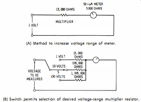
Fig. 2-8. Basic VOM voltage-measuring circuit.
CIRCUIT FOR MEASURING AC VOLTAGE
In a VOM, the basic circuit generally used for measuring ac voltage is essentially the same as that used for measuring dc voltage. The main difference is that for ac voltage measurement, a rectifier is included in the circuit.
The rectifier may be either a half-wave rectifier, as in Fig. 2-9A, or a full-wave rectifier. Often a bridge circuit, as in Fig. 2-9B, or a double half-wave rectifier, as in Fig. 2-9C, is used. Usually, but not always, a copper-oxide rectifier is employed, rather than the selenium, silicon, germanium, or vacuum-tube types.
A rectifier permits current flow almost entirely in one direction. Therefore, it changes the ac voltage to be measured to a dc voltage in the form of a series of half sine waves. Thus, current flows through the d'Arsonval meter in one direction only, just as it does for dc measurement.
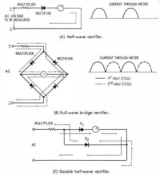
Fig. 2·9. Basic rectifier circuits in measurement of ac voltage. (A) Half-wave
rectifier. (b) full-wave bridge rectifier. (C) Double half-wave rectifier.
Because of the additional resistance of the rectifier in the circuit and because the current is not continuous for ac measurement, it is usually necessary for the designer of a VOM to use multipliers in the ac voltage-measuring circuit that are different from those used for dc voltage measurement. This would not be necessary if different calibrated scales on the faceplate of the meter were used for dc and ac. However, it might be confusing to search through the maze of calibrations on the faceplate for the desired ac or dc scale. Thus, designers generally agree that it is preferable to design the meter so that the same voltage scales can be used for both ac and dc.
The half-wave rectifier circuit shown in Fig. 2-9A is actually seldom employed in a high-quality VOM. The only important reason for this is that copper-oxide and other solid-state rectifiers conduct some current on the negative half cycles. Assume that a certain copper-oxide rectifier has a resistance of 200 ohms in one direction.
This is the direction in which it would best conduct on the positive half cycles. Then, typically, it would have a resistance of 100,000 ohms in the other direction. Therefore, on negative half cycles it would conduct very little current in most circuits. But in a VOM circuit, the multiplier resistors have fairly high values on all but the lowest voltage ranges, and the reverse current may be appreciable compared to the forward current.
To illustrate, in Fig. 2-9A the resistance of the multiplier, rectifier, and meter in the forward direction might be 2,000,200 ohms on the 100-volt range, and in the reverse direction the resistance might be 2,100,000 ohms. Then, on positive half cycles the current would be very close to 50 microamperes. But on negative half-cycles, instead of the current being practically zero, it would be 100 divided by 2,100,000, or approximately 48 microamperes. The 50 microamperes going through the meter for all the positive half cycles would tend to deflect the pointer to full scale, and the 48 microamperes going the opposite direction through the meter on negative half cycles would tend to swing the pointer nearly as much in the other direction. The two opposing forces would be occurring only 1/20 of a second apart, so the net effect on the meter reading would be the difference between the forward and reverse current, or 50 - 48 = 2 microamperes. Rather than causing the meter to indicate 100 volts, then, this 2 microamperes would cause it to indicate only 4 volts on the 100-volt scale.
Whenever half-wave rectifier circuits are employed in VOM's, they are often the double half-wave type shown in Fig. 2-9C. For this circuit, the overall measuring circuit has approximately the same resistance for both the half cycles of measured ac; but on the reverse, or negative, half cycles, the second rectifier (X2) shunts the reverse current around the meter, thus preventing any appreciable part of the forward, or positive, half cycles from being cancelled.
BASIC VOM CIRCUITS FOR RESISTANCE MEASUREMENT
The basic circuits used in VOM's for measuring dc current and dc and ac voltage have been discussed. The remaining major function of a VOM is to measure resistance. Since resistance is measured in ohms, a resistance-measuring circuit is called an ohmmeter circuit.
There are two types of ohmmeter circuits : the series-ohmmeter circuit and the shunt-ohmmeter circuit. Either one or both may be found in a typical good-quality VOM.
The series-ohmmeter circuit includes a source of power (usually a battery), a calibrated meter, a fixed current-limiting resistor, and a variable resistor, as shown in Fig. 2-10A. Of course, there is also a pair of test leads which connect to this resistance-measuring circuit.
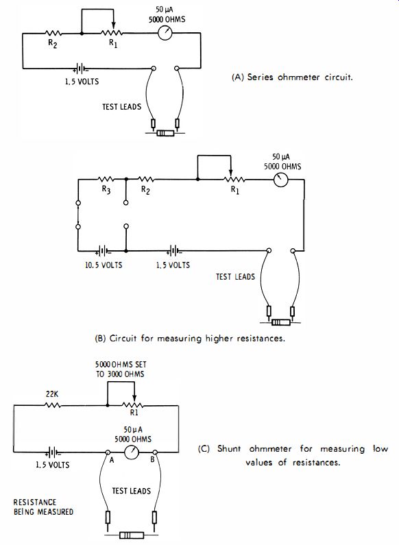
Fig. 2-10. Resistance-measuring circuits. (A) Series ohmmeter circuit. (B)
Circuit for measuring higher resistances. (C) Shunt ohmmeter for measuring
low values of resistances.
For the purpose of discussion here, assume that a 50-microampere meter having a resistance of 5000 ohms is used, that the value of current-limiting resistor R2 is 22,000 ohms, that RI is a 5000-ohm potentiometer adjusted to a value of 3000 ohms, and that the battery is 1.5 volts. With a total of 30,000 ohms, and with 1.5 volts applied to the circuit, if the resistance being measured is zero ohms, the circuit current should be exactly the 50 microamperes required by the meter to read full scale. In fact, this is essentially how an ohm-meter is calibrated for zero ohms. The tips of the test probes are held together, and the variable resistor is adjusted until the meter reads exactly full scale, corresponding to zero ohms. Now, if the test probes are placed across the terminals of a resistor with a higher value than zero ohms, the deflection of the pointer will not reach the zero-ohms point on the scale. Assume further that the resistance being measured has a value of 30,000 ohms, the same as the measuring circuit. The meter now will be deflected to a % full-scale value, since with twice the resistance, the current will be % as great. If the probes are placed across the leads of other resistors that have values greater or less than 30,000 ohms, the indication will be either below or above the 1/2-scale reading of the meter, respectively, by an amount that depends on the difference of the resistance value.
Thus, the meter faceplate can be calibrated to read various values of resistance.
Theoretically, this circuit will respond to any value of resistance between 0 and infinity. But, in practice, with the values suggested here, resistance less than 1000 ohms and above 500,000 ohms cannot be measured accurately. This is because these values of about 1000 ohms and 500,000 ohms are very small and very large, respectively, compared to the measuring-circuit total resistance of 30,000 ohms.
The 1000-ohm resistor would cause a deflection of about 97% of full scale, and the 500,000-ohm resistor would cause a fairly feeble deflection; neither could be read very accurately.
Circuit for Measuring Higher Resistances
A method of extending the high-end range of an ohmmeter is shown in Fig. 2-10B. A 210,000-ohm resistor (Ra) and a 10.5-volt battery have been switched into the circuit. With the test leads shorted, the current will be: (10.5 + 1.5 ) 12 (210,000 + 22,000 + 3000 + 5000 ) - 240,000 50 microamperes
This is the current required for full-scale deflection. However, at the midrange point on the scale, 240,000 ohms can be read. This is compared to the first example with 30,000 ohms for the 1.5-volt battery and 30,000 ohms of total circuit resistance. Furthermore, assuming accurate reading down to the 10% deflection point of 5 microamperes on the meter, it will be possible to measure resistance up to:
12 5 X 10^-6 - 240,000 = 2,400,000 - 240,000 = 2,160,000 ohms or 2.16 megohms.
With the beginning of the 1.5-volt battery and with 30,000 ohms of circuit resistance, the 10% deflection point reading would be: 300,000 - 30,000 = 270,000 ohms Circuit for Measuring Lower Resistances It was shown that the circuit in Fig. 2-10A was not satisfactory for measuring low values of resistance. Of course, the circuit in Fig. 2-10B is even less suitable. In commercial ohmmeter circuits, the very low values of resistance are measured by use of the shunt-ohmmeter circuit shown in Fig. 2-10C. The test leads in the measuring circuit now connect across the meter. When the test probes are connected across an unknown value of resistance, the current in the measuring circuit is reduced, part of it going through the meter and part through the unknown resistance. If the resistance is 5000 ohms, the equivalent resistance across points A and B is reduced to 2500 ohms. Although the total current in the circuit increases now to 1.5 divided by 27,000, or about 55 microamperes, the current through the meter itself is half that amount, or about 27.5 microamperes.
Thus, measuring a resistance of 5000 ohms would give an indication on the scale at slightly above midrange. Further variations of the shunt-ohmmeter circuit of Fig. 2- 10C will permit reading even lower values of resistance. In some VOM's, for certain ranges of resistance measurement, a combination of a series circuit and the shunt circuit is employed.
Meter Overload Protection
Most VOM's include some means of protecting the meter movement from damage due to overload, or excessive current. In some meters this overload protection is in the form of either a fuse or a circuit breaker which opens the circuit when excessive current flows through the meter. In other instruments the protection is a zener-diode circuit connected across the meter movement. For normal current values, the diode is an open circuit. If the voltage across the meter becomes too high, the zener diode conducts, shunting part of the current around the meter, thus protecting it from damage.
MULTIPLE USE OF SCALES IN A TYPICAL VOM
In a commercial VOM the multiplier and shunt resistances for different ranges of voltage, current, and resistance measurement are chosen so that the range-selecting switch can be labeled logically and so that the calibrated scales on the meter faceplate can represent several ranges.
For example, for the VOM shown in Fig. 2-11, the calibrated scale second from the top of the faceplate is labeled 0, 50, 100, 150, 200, and 250. This scale is used for the following functions and ranges : dc volts : 0-2 .5; 0-250. ac volts : 0-250. The third scale from the top has two separate calibrations ; the upper set is labeled 0, 10, 20, 30, 40, and 50; the lower set is labeled 0, 2, 4, 6, 8, and 10. These scales are used for the following functions and ranges : dc volts : 0-1; 0-10; 0-50; 0-250; 0-500; 0-1000. ac volts : 0-2.5; 0-10; 0-50; 0-250; 0-500; 0-1000. dc current: 0-1 mA; 0-10 mA; 0-100 mA; 0-500 mA. The fourth scale from the top is for use in making low ac voltage measurements, between zero and 2.5 volts; this scale is labeled 0, .5, 1.0, 1.5, 2.0, and 2.5.
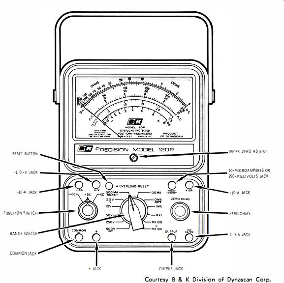
Fig. 2-11. Identification of important features of a typical VOM.
The bottom scale is for measuring ac output volts, such as the out
put signal from an audio amplifier; the value measured is specified in terms of decibels, or dBs. This bottom scale starts from -20 at the left side and progresses toward the right through -10, -4, -2, 0, and then is marked off in positive values of 2, 4, 6, 8, and 10.
The top scale on the meter faceplate of Fig. 2-11 is used for measuring resistance. If the range switch is on the R x 1 position, the resistance values are read directly from the meter. With the range switch in the R x 100 position, the values indicated on the meter are multiplied by 100; and with the range switch in the R X 10K position, the values indicated are multiplied by 10,000. Note that the figure 10 appears at about midrange on the ohms scale.
For resistance measurements, if the range switch is set to R x 1, this number 10 indicates 10 ohms; for the R X 100 range, the 10 indicates 10 x 100, or 1000 ohms; and for the R X 10,000 range, the 10 indicates 10 X 10,000, or 100,000. Note that on this highest resistance range it is possible to read resistances accurately up to the point marked 500, or 500 X 10,000 ohms (5 megohms ). Low resistance values can be read on the R x 1 scale to well below 1 ohm.
The round knob at the lower center of the meter is the ZERO OHMS control, equivalent to H1 in Figs. 2-10A, B, and C. The knob is used for setting the pointer deflection exactly to full scale when the test probes are shorted together.
SENSITIVITY OF A VOM
One of the most important characteristics of a VOM is its sensitivity rating. This is specified in terms of ohms per volt. The higher the ohms-per-volt rating, the more sensitive the VOM. The sensitivity rating is usually shown on the face of the meter or given in the instructional manual. It can also be determined by using one of the following formulas :
1,000,000 sensitivity 0 ms per va t = -E x III
= A Is /-t
where, Efs is the voltage required for deflecting the meter full scale, Rill is the resistance of the meter movement, uA is the current in microamperes required for full-scale deflection of the meter.
The sensitivity may also be determined by dividing the total resistance of the circuit for the range in use by the voltage value of that range. To illustrate, suppose the 0- to 12-volt dc range is in use and that for this position of the range switch there are 240,000 ohms in the measuring circuit. The sensitivity of the measuring circuit is then:
240,000/12 = 20,000 ohms per volt
The same ohms-per-volt rating would apply to all dc ranges of the VOM. For the ac ranges, however, the sensitivity is usually rated lower. The lower rating is due to the leakage resistance of the rectifier in the reverse direction and to the fact that the rectified current is not continuous. The ac sensitivity of the VOM of Fig. 2-11 is 5000 ohms per volt. Its dc sensitivity is 20,000 ohms per volt. In practice, it is usually important to have a high dc sensitivity rating, the ac sensitivity rating not being quite so important. In many applications, however, a VOM having a sensitivity of only 1000 ohms per volt will be satisfactory. A VOM of 1000 ohms per volt is much less expensive than one of 20,000 ohms per volt, and the measurements made with the less-expensive instrument will be just as accurate when these voltage measurements are made across resistances or impedances of relatively low value.
Loading Effect of a Meter
The need for using a high-sensitivity VOM for voltage measurement in high-impedance circuits becomes apparent if the results are examined when one with low sensitivity is used.
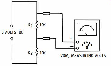
Fig. 2-12. Circuit showing loading effects caused by VOM.
For instance, in the circuit of Fig. 2-12, with 3-volts dc applied across two 10,000-ohm resistors (R1 and R2 ) in series, the drop across each resistor is 1.5 volts, and the circuit current is :
3 I = 20,000 = 0.00015 ampere
Now assume the use of the 3-volt range on a 1000-ohms-per-volt meter in order to measure the voltage across R1. On the 3-volt range, the total internal resistance of the VOM is only 3000 ohms.
As soon as the VOM test leads are connected across R1, the 3000 ohm resistance of the meter in parallel with the 10,000 ohms of RI has an effective value of approximately 2300 ohms, which changes the total circuit resistance to 10,000 plus 2300, or 12,300 ohms.
The circuit current now becomes : 3 I = 12 300
= 0.000244 ampere.
And the voltage drop across the terminals of R1 to which the VOM leads are connected is : E = 2300 X 0.000244 = 0.56 volt The meter will read this value instead of 1.5 volts which will actually be the voltage across R1 when the VOM is not connected.
The change in circuit conditions caused by connecting a meter to a circuit is called the loading effect of the meter. It is apparent that in the example just shown, the loading effect of the 1000-ohms per-volt meter was considerable. If now a 20,000-ohms-per-volt VOM is used to measure the voltage across R1 in Fig. 2-12, the loading effect is considerably less. On the 3-volt range, a 20,000-ohms-per-volt instrument has an internal resistance of 60,000 ohms. This 60,000 ohms across the 10,000 ohms of R1 gives a combined resistance of approximately 8,600 ohms. Then, by calculating as before, the voltage across R1, with the 20,000-ohms-per-volt VOM connected, is approximately 1.4 volts. Although this represents an error of about 7%, it is a considerable improvement over the reading of 0.56 volt obtained with the 1000-ohms-per-volt instrument.
Of course, a 1000-ohms-per-volt VOM does not have a serious loading effect on every circuit. For instance, the use of the 150-volt range to measure 100 volts across a 1000-ohm resistor would give highly accurate results. The 150-volt range has a resistance of 150,000 ohms.
This 150,000 ohms across the 1000 ohms of the circuit under test would have a negligible effect. Of course, a 20,000-ohms-per-volt instrument is not the final answer to measurements in all high-impedance circuits either. If such a VOM is used on the 1.5-volt range to measure 1 volt across 100,000 ohms, the loading effect of the 30,000-ohm meter resistance on this range would be quite serious. However, for a high percentage of the measurements in electronics work, the 20,000-ohms-per-volt instrument provides accurate results.
For the remaining percentages, either a higher-resistance VOM is required or, more often, an electronic meter is employed. The advantage of an electronic meter, such as the VTVM, with respect to circuit loading is considered later in this guide.
Higher-Sensitivity VOMs
Volt-ohm-milli-ammeters having sensitivities of 100,000 ohms per volt, 200,000 ohms per volt, and even higher are also available. In a typical 100,000-ohms-per-volt instrument, the meter movement is rated at 10 microamperes for full-scale deflection. For measuring voltages of 100 volts or more across circuit resistances of 10 megohms or more, a 100,000-ohms-per-volt VOM has even less loading effect than the typical electronic meter. In these higher-sensitivity VOM's, the meter movement employed is usually the taut-band suspension type.
OUTPUT-MEASUREMENT CIRCUIT
Input and output signals of amplifiers are sometimes measured or specified in watts, sometimes in volts, and sometimes in decibels (dB). Where it is desired to measure in volts, the proper ac range of the VOM is used. Assuming that the amplifier is for the audio-frequency range and that the VOM has a good response in this range, the reading obtained will indicate the rms, or effective, value of the audio voltage.
If power in watts is the desired measurement, the square of the measured voltage (E) is then divided by the resistance (R) of the input or output circuit. That is : E? Power in watts = R As an example, 90 volts ac is measured across an amplifier output circuit impedance of 600 ohms. Then the output power may be calculated as:
90? 8100 P = 600 = 600 = 13.5 watts
As in the VOM's described previously, most higher-sensitivity VOM's have a specially calibrated scale on the meter faceplate. If no dc is present in the ac or audio signal to be measured, one of the ac facilities of the meter may be used to make the measurement in decibels. Ordinarily, however, a VOM will have a test-lead jack, such as the second jack from the bottom right in Fig. 2-11, that is labeled OUTPUT. To use this facility, one test lead is plugged into the COMMON jack, and the other is plugged into the OUTPUT jack.
Typically, the only difference between the OUTPUT jack and the ac function of the VOM is that a capacitor is employed in series with the OUTPUT jack in order to remove any dc from the measurement being made.
In the meter of Fig. 2-11, the value in decibels may be read directly from the dB scale when the range switch is in the 2.5-V position. Higher decibel values may also be read by following directions for the particular instrument being used.
The decibel values are usable directly only for measurements on a 600-ohm circuit. Furthermore, the scale is calibrated on the basis that 0 dB is equal to 1 milliwatt and only, as mentioned earlier, on a 600-ohm circuit. Decibel measurements on circuits other than 600 ohms may be made, but then the readings obtained will only be relative. Charts and graphs are available for converting decibel readings in circuits of various impedances to actual decibel values with respect to 1 milliwatt taken as the 0-dB reference. Often these charts and tables are included in the VOM manufacturer's instruction manual.
QUESTIONS
1. What type of meter movement is used in most VOM's?
2. What is the purpose of the function switch in a VOM?
3. Name the main components of the d'Arsonval meter movement.
4. If a meter movement appears to be defective, and close visual inspection fails to reveal the source of trouble, what should be done to repair the meter movement?
5. What part of the meter movement sometimes is referred to as the armature?
6. If the pointer of a meter movement does not rest at zero when there is no current through the meter, what can be done to "zero" the pointer?
7. Which meter movement would be referred to as being more sensitive, one requiring 50 microamperes for full-scale deflection, or one requiring 100 microamperes?
8. If 40 microamperes causes full-scale deflection of a typical meter movement, how much current will cause half-scale deflection of the pointer?
9. What may happen if considerably more than the rated full-scale current is applied to a meter movement?
10. How can a resistor be used to extend the current-measuring upper limit of a meter?
11. If a meter movement rated at 1 milliampere full scale has a resistance of 500 ohms, determine the value of the shunt required if the movement is to measure 10 milliamperes full scale.
12. In a typical VOM, what provision is made for measurement of current on one or more full-scale ranges?
13. What method permits use of a meter movement to measure voltages much higher than the full-scale voltage of the meter?
14. What size of resistor should be used as a multiplier for measuring 1000 volts full scale on a meter movement having 1000-ohms resistance and a full-scale current rating of 1 mA?
15. Since the d'Arsonval meter movement responds only to dc current, how can it be used for measurement of ac voltage and current?
16. Sketch the schematic of a typical meter rectifier circuit.
17. In many VOM's, why are the values of multiplier resistors employed in the ac-voltage circuit different from those employed in the dc: voltage circuit?
18. In an ohmmeter, or resistance-measuring circuit, assume that the resistance of the measuring circuit is normally 5000 ohms with the test leads shorted for full-scale indication of the pointer. If the test leads are then connected across a resistor of 5000 ohms, what will be the relative amount of deflection of the painter?
19. Name the two basic types of ohmmeter circuits.
20. Which of these types is used for measurement of low values of resistance?
21. What is the purpose of the output-measurement facility of a VOM?
22. To what does the "sensitivity" rating of a VOM refer?
23. What is the sensitivity of a VOM that deflects full scale with 50 microamperes through the meter movement?
24. In the usual VOM, how does the sensitivity rating for the ac ranges compare with that for the dc ranges?
25. What is meant by "loading effect"?