Some basic circuits and features of VOM's have been considered so far. Now let's examine the physical makeup of the VOM with regard to its components-in other words, types of test leads used, shunt and multiplier resistors, switches and potentiometers, batteries, fuses, and other components. The purpose is to get an idea of what makes up the VOM both inside and outside. Many of the components used in VOM's will also be found in other instruments to be considered later.
TEST LEADS, PROBES, AND CLIPS
Ordinarily, one pair of test leads is provided by the manufacturer of a VOM. Leads about 3 feet long, like those in Fig. 3-1, are common.
One has red insulation, and the other has black insulation. Fastened to one end of each test lead is a plug for inserting the lead into the VOM jack. Usually the plug on the black test lead is plugged into the jack marked COMMON, NEGATIVE, or MINUS. The plug on the red test lead is inserted into the other jack, which may be labeled OHMS, VOLTS, AMPS, OUTPUT, etc. At the other end of each test lead is usually either a spring-loaded clip (Fig. 3-1A), with jaws for fastening the clip to the circuit or component being tested, or a test probe (Fig. 3-1B) that is held in the hand and touched to the circuit or component. Sometimes the black test lead comes with the clip, and the red lead comes with the test probe. Other special-purpose test leads also are available.
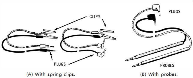
Fig. 3-1 . Typical VOM test leads. (A) With spring clips. (B) With probes.
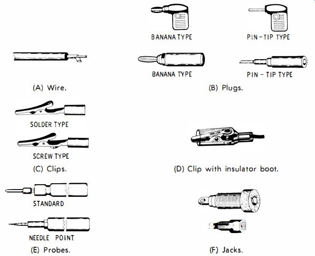
Fig. 3-2. Test-lead parts.
The owner of a VOM may want to obtain additional test leads or to replace leads that have become defective. These may be purchased from the VOM manufacturer, a local supplier, or a mail-order house. When ordering test leads, the model number of the instrument should be specified since not all test leads are interchangeable, especially with regard to the tips of the plugs inserted in the meter jacks. It is also practical to assemble your own test leads, using the proper wire, plugs, and clips or probes.
Test-Lead Wire
Standard test-lead wire is available from several manufacturers and suppliers. The usual type, as shown in Fig. 3-2A, is about 1fs inch in diameter. The outer covering is an insulation material; inside this material are stranded-wire conductors which are spiral-wrapped in a cotton covering for added strength. The wire usually is No. 18, but in some leads No. 22 wire is used. All, or nearly all, of the strands are copper. Standard test-lead wire is generally rated at either 5000 or 10,000 working volts. Test leads should be safe and flexible for easy use, and the conductors should have a low resistance. Therefore, ordinary wire, even if it is similar in appearance, is not satisfactory since it usually tends to tangle and kink, or to be too stiff.
Plugs
Test-lead plugs are made with several types of conductive tips and in several shapes or configurations (Fig. 3-2B ). Typically, the plugs are either the pin-tip or the banana-plug type which is larger in diameter and made of spring-like sections for added tension and better contact in the VOM jack. Most manufacturers of higher-quality instruments provide the banana-plug type.
The body of the plug is generally either a red or a black hard rubber or plastic that covers the tip to protect the user from shock.
On preassembled test leads, the two halves of the body may be riveted together; but on plugs purchased for assembly or as replacements, the two halves are usually fastened together with a machine screw and nut that may be removed for connecting the test lead. In other types of plugs, the tip is covered with a barrel-shaped plastic cylinder that may be unscrewed from the tip. On one version of this type of plug, the wire of the test lead must be soldered to the tip terminal; on another, the wire is inserted through the back of the tip, passed through a hole leading out the side of the plug, and fastened by the pressure of a cap nut screwed on the back end of the plug. The most reliable method is to solder the wire to the plug.
Clips and Probes
The probes or clips used at the measuring end of the test leads are also of several different types. The spring types with jaws are generally classified according to shape or assembly as either alligator, crocodile, or mesh-tooth clips. There are several physical sizes of each of these : heavy-duty, standard, or miniature. Some are provided with protective plastic handles (Fig. 3-2C) or with rubber or plastic protect{ve coverings (Fig. 3-2D) to prevent shocks to the user while he is handling the probes. Both the solder and screw-terminal methods for fastening are available. Also available are clips constructed so that they can be attached to the end of a probe tip, thus making a single set of test leads quite versatile.
Several types of test probes also are available. The types most frequently used are shown in Fig. 3-2E, and consist of a pointed or thin tip fastened to a protective handle of 4 to 6 inches in length, usually colored red or black. The test-lead wire is soldered or fastened by a screw or a pressure nut, depending on the type of probe utilized.
Test leads, probes, plugs, and clips should be inspected regularly for good electrical connection. Look for frayed or loose strands of wire that could cause a shock or a short circuit, and for breaks in the test-lead insulation for the same reason. The proper size test-lead plugs should always be used. Never force plugs that are too large into the jacks (examples shown in Fig. 3-2F ) of a VOM, or proper contact might be hard to obtain later. Plug tips that are too small should not be used, not only because of the poor contact that might result, but also because the intermittent contact might cause arcing between the tip and the jack. This could result in pitting and perhaps a defective electrical connection when the proper size is later employed.
High-Voltage Test Probe
Many VOM's are designed to measure up to 5000 to 6000 volts or more, with the regular test leads provided. No attempt should ever be made to measure voltage any higher than that for which the meter was designed, unless a high-voltage probe is employed (Fig. 3-3 ). It is better to obtain a high-voltage probe made for your instrument rather than to construct one or adapt one made for another VOM.
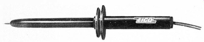
Fig. 3-3. High-voltage test probe. Courtesy EICO, Electronic Instrument Co.
The voltage-dropping or multiplier resistor contained in the specially designed handle of a high-voltage probe makes it possible to adapt a VOM for measuring higher voltages. The resistor value is selected by the manufacturer to match the voltmeter ranges and sensitivity. Instructions accompanying the high-voltage probe list the ranges and multiplying factors for interpreting the readings.
The method of operation of a high-voltage test pro be is fairly simple. Suppose a particular meter is rated as 20,000 ohms per volt. Then, on the 3-volt range the VOM has a resistance of 60,000 ohms.
To measure up to 30,000 volts when the VOM is set to the 3-volt range, a total measuring-circuit resistance of 30,000 x 20,000, or 600 megohms, is required. The multiplying resistor in the handle of the probe must then have a value of 600,000,000 - 60,000, or 599,940,000 ohms. When the VOM is in use, the common lead would be connected to one side of the high-voltage source, and the tip of the high-voltage probe would be connected to the other side. With the range switch set to 3 volts, the reading is obtained from the 3-volt scale, multiplying the reading obtained by 30,000/3, or 10,000. However, rather than dealing with the cumbersome multiplier 10,000, you could use the 3-volt range setting of the selector switch, read from the 300-volt scale, and multiply the reading by 100. The high-voltage probe can be adapted for use at other high-voltage ranges by employing other settings of the range-selector switch, other scales on the meter, or both.
An important feature of a high-voltage probe is that it is designed to protect the user from shock. The flange located near the upper end of the handle (Fig. 3-3 ) prevents the user from placing his hand too close to the high-voltage end of the voltage-dropping resistor or too close to the high-voltage circuit being measured. The dropping resistor is made physically long (or consists of several resistors in series ) to distribute the voltage gradient over a path as long as possible. This long path helps to prevent arcing in the resistor and reduces the danger of shock to the user.
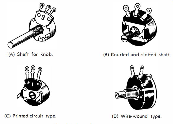
Fig. 3-4. Potentiometers. (A) Shaft for knob. (B) Knurled and slotted shaft.
(C) Printed-circuit type. (D) Wire-wound type.
RESISTORS USED IN VOMs
The typical resistor types used in VOM's for multipliers and shunts often have at least 10/0 accuracy. According to the manufacturing techniques employed, they are known as deposited-carbon, carbon film, deposited-film, fixed-film, or wire-wound types. Shunt resistors of very low value consist of a piece of copper or iron wire or strap with a resistance that has been very accurately determined.
Of course, should a resistor in a VOM become damaged (for example, from excessive current ), it should be replaced by one of identical type, preferably obtained from the manufacturer or the manufacturer's distributor.
Practically every VOM has at least one potentiometer, that one being used for the ohms zero-adjustment. Potentiometers used in VOM's are usually of the carbon type. Some examples of the types of potentiometers found in measuring instruments are shown in Fig. 3-4. The example in Fig. 3-4A has a shaft that is long enough to extend through the instrument panel ; the shaft is designed so that a knob may be fastened to the end. The one shown in Fig. 3-4B has a knurled shaft for turning with the fingers; in addition, a slot in the end of the shaft is for screwdriver adjustment. The potentiometer shown in Fig. 3-4C is a printed-circuit type, which mounts to the board by means of the tabs on each side and is screwdriver adjustable. Fig. 3-4D shows a wire-wound potentiometer; this type is usually not employed in a VOM, especially in the voltage-measuring circuits, because of its inductance which affects the higher-frequency measurements.
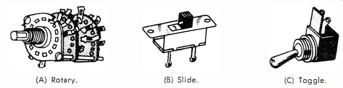
Fig. 3-5. Switches used in VOM's. (A) Rotary. (6) Slide. (C) Toggle.
SWITCHES
Nearly every VOM employs at least one rotary selector switch for changing from one range of voltage, current, or resistance to another. This switch consists of one to four, or more, wafers, with one or two decks of switch contacts per wafer, and two to twelve, or more, contacts per deck. An example of one type of rotary selector switch is shown in Fig. 3-5A. Sometimes a slide switch, similar to the one in Fig. 3-5B, is employed in a VOM. There are several types : single-pole, single-throw (spst ); single-pole, double-throw (spdt); double-pole, single-throw (dpst ); or double-pole, double-throw (dpdt ). Toggle switches (Fig. 3-5C) also are employed with spst, spdt, dpst, or dpdt contacts.
Some VOM's have a number of push-button switches for changing functions and ranges.
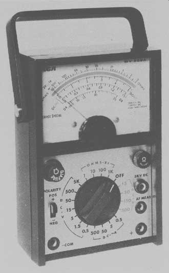
Fig. 3-6. Example of a VOM, RCA Model WV-S29A.
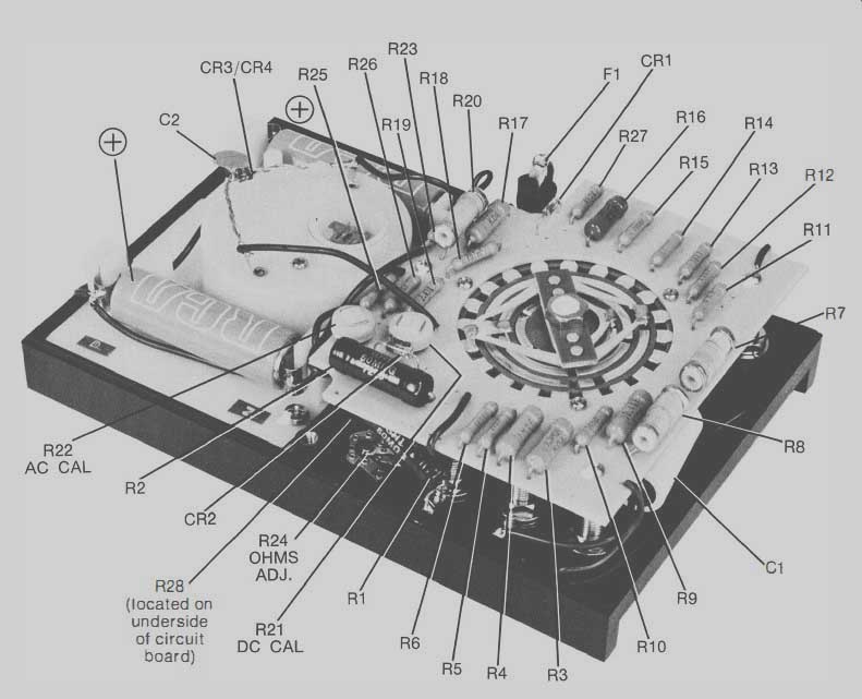
Fig. 3-7 RCA
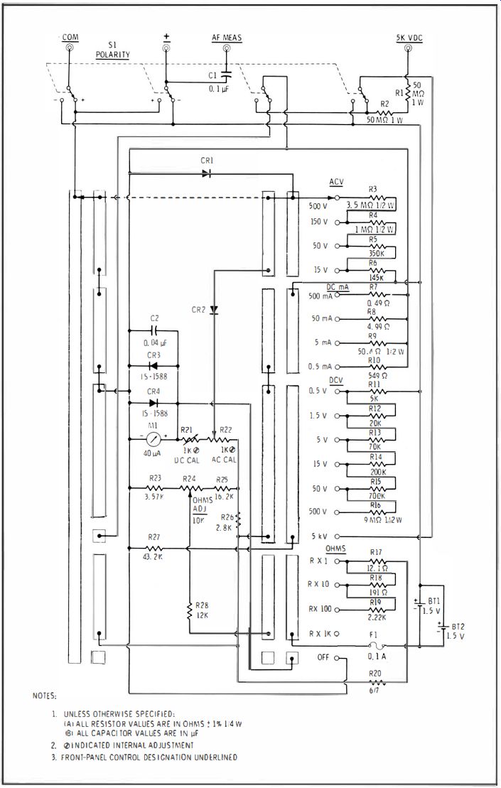
Fig. 3-8. WV-S29A schematic diagram.
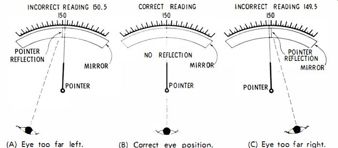
Fig. 3-9. Use of mirrored scale to avoid parallax error. (A) Eye too far left.
(B) Correct eye position. (C) Eye too far right.
TYPICAL VOM INTERNAL DETAILS
An internal view of the RCA WV-529A VOM in Fig. 3-6 is shown in Fig. 3-7, and the schematic is shown in Fig. 3-8. The appearance and features of some of the components can be identified by comparison of the internal view and the schematic. At this time we will point out a few of the parts shown in the internal view of Fig. 3-7. The dc current shunts are resistors R7, R8, R9, and R1O, shown at the lower right. The ac voltage multipliers are R3, R4, R5, and R6 at the bottom center. The dc voltage multipliers at the upper right are R11, RI2, R13, and R14. The resistance-measuring circuit includes resistors R17, R18, RI9, and R20 at the upper left. Diode CR1 is the rectifier for the ac measuring circuit; diodes CR2 and CR3 provide overload meter protection. The control for ohms adjustment is R24 at the lower center. The combination range and function switch is the circular device near the right center.
A feature that is included in a relatively high percentage of meters is an anti-parallax mirror, shown on the meter face of Fig. 3-6. This mirror makes it possible to read the pointer indication more accurately by eliminating parallax error. This is the error resulting when the eye of the observer is not directly in front of the meter pointer, as shown in Figs. 3-9A and 3-9C. In Fig. 3-9A, with the observer's eye too far to the left, the pointer appears to be at 150.5 volts; in Fig. 3-9C, with the observer's eye too far to the right, the pointer appears to be at 149.5 volts. However, in Fig. 3-9B, the observer knows that his eye is directly in front of the pointer because the pointer and its mirror image coincide and the correct reading, 150 volts in this case, is observed.
VOM ACCESSORIES
Sometimes accessory items may be included with a VOM when it is purchased, or the accessories may be obtained separately from the manufacturer. Various types of accessories are available; some make it easier to use the instrument by making measurements more accurately or more conveniently; others extend the range of the instrument. Some examples of these will be considered briefly.
External High-Current Shunts
For most VOM's, external shunts are available for extending the range upward in dc current measurement. The shunt usually plugs into the front-panel jacks of the VOM and is calibrated for the specific VOM to extend a certain range to, say, 30 amperes, 60 amperes, or 120 amperes . External shunts should be obtained from the manufacturer for the exact model of instrument employed.
Carrying Cases and Stands
Carrying cases are available for most VOM's; usually these are leather, but some are hard plastic. A carrying case is a good investment for several reasons. Its main function is to provide portability.
A carrying case also protects the instrument from physical shock, moisture, dust, dirt, and objects that might strike the VOM.
Also available are metal , wire, rubber, or plastic stands that are designed so that the VOM may be placed at an angle convenient for use. Most instruments are designed in such a manner that they can either stand upright or lie flat on the bench or other working surface.
In the average situation in which measurements are made, it is more convenient for the user if the VOM can be tilted backward.
Adaptor Plug-In Units
Some manufacturers make plug-in adaptor units for popular models of VOM's. A plug-in adaptor unit, for example, may convert a VOM to an audio wattmeter for the installation and service of high-fidelity systems and other audio systems, or for telephones, intercoms, and public-address systems. By means of a switch, the desired load impedance (4, 8, 16, or 600 ohms ), may be selected. In the direct position of this switch, normal use of the VOM is restored without removal of the adaptor.
Other adaptors can convert a VOM to a: transistor tester, temperature tester, ac ammeter, microvolt attenuator, battery tester, milli-ohmmeter, or extended-range dc ammeter. The main advantage of an adaptor unit (over purchase of a special measuring instrument) is that some savings are obtained since the adaptor does not include a meter movement of its own, instead utilizing the one in the VOM.
QUESTIONS
1. What characteristics should the wire used for test leads have?
2. Describe the important features of a high-voltage test probe.
3. If a shunt or multiplier resistor in a VOM should become damaged, what should be considered before replacing the resistor?
4. What is the tolerance rating of typical shunts and multipliers in VOM's?
5. In Fig. 3-8, which component is the zero-ohms potentiometer?
6. What is parallax error?
7. What device included in some VOM's reduces the likelihood that parallax error will occur?
8. What is an external high-current shunt?
9. What should you look for when checking over a pair of test leads?
10. What is the purpose of the flange that is included in the construction of the typical high-voltage test probe?