The specifications for a VOM describe the functions and limitations of the VOM. Knowing the "specs" for your VOM, or one you are about to purchase, is very important in using it effectively.
SPECIFICATIONS AND THEIR MEANING
Some of the specifications and terms important to know include sensitivity, accuracy, and frequency response.
Sensitivity
Sensitivity has previously been discussed to a considerable extent. This specification indicates how many volts, millivolts, milli-amperes, or microamperes are required for full-scale deflection of the meter. It has been shown that a meter having a movement rated at 1000 ohms per volt has 1 milliampere flowing through the movement when the pointer is deflected full scale. Also, a 20,000-ohms per-volt instrument is deflected full scale when 250 millivolts are applied to the movement terminals-at full scale, 50 microamperes are flowing through the movement. The 20,000-ohms-per-volt VOM is the most widely used for general electronics servicing work, but other instruments are available with sensitivity ratings of 100,000 ohms per volt, 200,000 ohms per volt, or more.
The sensitivity rating attributed to a VOM generally refers to its performance for measuring dc volts. For measuring ac volts the sensitivity generally is lower. For most better-quality VOM's the ac sensitivity is 5000 ohms per volt, sometimes 2000 ohms per volt; occasionally, ratings of 1000 or 10,000 ohms per volt (or more ) may be encountered, depending on the nature and the design of the rectifier circuits. For the lower ac ranges, sometimes a high ac sensitivity is quite useful, for example, when measuring a low-level input signal to an amplifier stage across a high-value grid resistor.
Insertion Loss
The term "insertion loss" is sometimes applied to a VOM and describes its sensitivity or loading effect when it is used for measuring current. For example, when a 20,000-ohms-per-volt VOM is used for measuring direct current, the insertion loss is usually specified as 250 millivolts. This 250 millivolts is called a loss because, when the meter is in the circuit, it reduces the voltage applied to the circuit being measured by 250 millivolts when the current deflects the pointer full scale. If the circuit voltage is fairly high compared to 250 millivolts, this loss is negligible. However, if the applied voltage is fairly close in value to 250 millivolts, and if this applied voltage is fixed, the current reading obtained will not be a true indication of the amount of current in the circuit under normal conditions. For example, in Fig. 4-1 the applied voltage is 0.5 volt, or 500 millivolts, and the value of R is 10,000 ohms. By Ohm's law, the current will be 0.5 / 10,000 = 0.00005 ampere, or 50 microamperes.
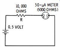
Fig. 4-1. Insertion loss due to presence of current-measuring meter.
For a 20,000-ohms-per-volt meter movement, there will be no shunt when the switch is set for the 50-microampere range, so the resistance contributed to the circuit by the meter will be 250 millivolts/50 microamperes, or 5000 ohms. This 5000 ohms in series with the 10,000 ohms of R brings the circuit resistance to 15,000 ohms. And, under this condition, the current now flowing in the circuit and indicated by the meter will be 0.5 / 15,000, or 33 micro-amperes. The voltage applied to R (the voltage drop across it ) will be 0.000033 X 10,000, or 0.33 volt. The loss contributed by the meter will be 0.000033 X 5000, or 0. 165 volt, approximately. Thus, in this case, the insertion loss is 165 millivolts. It is only when the circuit conditions are such that the pointer is deflected full scale when the meter is in the circuit that the insertion loss will be the full 250 millivolts specified.
Accuracy of VOMs for Voltage and Current Measurements
The accuracy specified for most VOM's is between 2 and 5% for dc voltages, and 2 and 10% for ac voltages. It might be important in some cases to keep in mind exactly how this accuracy factor can affect a reading. Assume that you are using a VOM with an accuracy given as ±3% on the dc voltage ranges. This 3% does not mean that any dc reading obtained will be accurate to within 3%. What it does mean is that the reading obtained will be accurate within plus or minus 3% of the maximum value of the range employed.
Suppose, for example, the 3-volt dc range is used. Then, the reading obtained might be higher or lower than its true value by the amount of 3% of 3 volts or 0.03 X 3 = 0.09 volt. Thus, if the pointer indicates 2.5 volts, the actual voltage might be either 2.5 - 0.09 = 2.41 volts, or 2.5 + 0.09 = 2.59 volts. Similarly, an actual voltage of 2.0 volts might result in a reading any where between 2.09 and 1.91 volts, a possible error of 4.5%. An actual voltage of 0.5 volt might result in a meter reading between 0.59 volt and 0.41 volt, a possible error of 18%. Thus, on any particular range, the most accurate readings are obtained when the pointer is being deflected as near full scale as possible, and the chance for an erroneous reading increases rapidly for readings of lesser and lesser deflection of the pointer.
A general rule of thumb is that voltage and current readings should be taken in the upper % of the scale. Then, when measuring a voltage somewhere in the vicinity of, for example, 0.4 volt, the 0- to 0.5 volt range rather than the 0- to I-volt or the 0- to 3-volt range should be used.
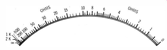
Fig. 4-2. Resistance scale of VOM showing crowded high-resistance end of scale.
For the usual good-quality VOM, typical accuracies are ±3% for dc ranges, ±5% for ac ranges, and ±3% for current ranges.
Accuracy of VOMs for Resistance Measurement
A VOM with an accuracy given as 3% for the dc voltage ranges will have the same basic accuracy for the measurement of resistance.
However, the accuracy for resistance measurement must be specified differently; the reason is that at maximum deflection on the resistance scale, the pointer indicates zero ohms, and at minimum deflection the pointer indicates infinity. For this reason the specification usually is given as being within so many degrees of pointer position or within so many percent of the length of the deflection arc.
On many VOM's the full arc of deflection between maximum and minimum scale values is 1000. Therefore, on these VOM's if the dc voltage accuracy is ±3%, the accuracy on the ohms scale is given as ±30, or as ±3% of the arc length. Determining from a particular resistance reading what the exact resistance might be (the extreme values it might lie between ) is not so simple as determining what the actual voltage might be for a particular reading. However, this is usually a minor matter so long as another general rule of thumb is followed. For resistance measurement, since the resistance scale is crowded toward the high-value end, as in Fig. 4-2, resistance readings should be made in the lower-value half of the resistance scale; the higher (toward zero ohms ) on the scale, the greater the accuracy. By staying above the half-way deflection point, the user is assured that the readings obtained will be accurate to within 6% for a ±3% scale-length specification. Since it is seldom necessary to measure resistance having a tolerance of less than 5% (most are 10 or 20%), staying within the upper half of the resistance scale will give fairly reliable results.
Interpreting Ohmmeter Scales
As mentioned earlier, the maximum deflection on a VOM ohmmeter scale is 0 ohms, and the minimum deflection is equivalent to infinite resistance. The scale of an ohmmeter is labeled progressively from right to left between 0 and some maximum value at which the scale effectively ends. Assume that the ohms scale of a VOM is calibrated or labeled for values between 0 ohms and 1000 ohms (1K). In other words, the scale ends at 1K. If the resistance ranges provided were R x 1, R x 100 and R X 100K, the manufacturer of the VOM could say that the VOM has resistance ranges of 0 to 1000 ohms, 0 to 100,000 ohms, and 0 to 100,000,000 ohms.
When measuring the value of a particular resistor, the proper range to use should be determined by looking at the midscale values for each of the ranges available. This midscale value for each range cannot be determined from the usual ranges specified for a VOM. One manufacturer might label his R X 1 range to end at 1K, while another might label his to end at 100K, which would be only a very small distance higher on the scale. The midscale value can be determined, of course, by looking at the ohms scale, but most manufacturers of quality VOM's list the midscale values as well as the end-scale values for each range. Therefore, when considering the purchase of a VOM, the midscale values given for each range probably will deserve more serious consideration than the end-scale values. A VOM that has a midscale figure of 400 ohms is not as useful for measuring low resistance values as one that is 10 ohms at midscale (as is shown in Fig. 4-2 ). Frequency Response Some VOM's are designed to be accurate on the ac ranges at 60 hertz (Hz) and, in practice, do not give a reliable indication at frequencies much above or below 60 Hz. Most of the best VOM's of the type previously considered are designed for a consistent response throughout the audio range. Manufacturers differ in the way they specify the response of their instruments. The statement "Rat from 50 Hz to 50 kHz" is a little indefinite. It might mean flat within % dB, within 1 dB, or within 3 dB. However, even if the accuracy were within 3 dB, it could be assumed that this would be a useful instrument for ordinary measurements over the given range.
An example of a method of specifying the response of a VOM a little more exactly would be as follows, "±% dB, 50 Hz to 50 kHz, reference 1000 Hz." This means that the VOM is accurate within ± % dB at any frequency between 50 Hz and 50 kHz as compared to its reading at 1000 Hz. Some manufacturers show frequency response for their instruments in the form of a graph, with separate graphs, if necessary, for each of the ac voltage ranges.
OTHER VOM SPECS
Many other specifications are applied to VOM's and other instruments for electrical measurement, especially laboratory instruments.
A detailed discussion of all of these would not be in line with the main objective of this guide. We will, however, mention briefly three of them: repeatability, tracking, and waveform influence.
Repeatability
Repeatability designates the ability of a VOM to repeat readings for successive measurements of the same quantity. Some meters will not give exactly the same reading after the test leads are removed and then reapplied to the same test points. This is due mainly to imbalance or friction in the bearings of the movement.
Tracking
Tracking refers to the ability of a meter to give accurate readings at any point on its scale. For instance, if a voltage is applied so that exactly full-scale deflection results, and then if the voltage is reduced to exactly 1/2 value, the deflection should be exactly 50% of full scale; similarly, if the voltage is reduced to exactly 1/4, the deflection should be exactly 1/4, and so on.
Waveform Influence Nearly all ac VOM's are designed for measurement of the rms values of sine waves. However, meters are deflected in proportion to the average value of the sine-wave half-cycles or the average value of whatever waveform is applied. If the waveform is not a sine wave, the value indicated probably will not represent the rms value of the waveform being measured. In circuits where pulses and distorted waveforms are being measured, remember this discrepancy.
In cases where it is important to know the exact value and nature of a voltage or current, the oscilloscope should be used.
BEFORE USING THE VOM
Before using a new VOM or before using a particular model not used before, the user should examine it closely, and the instruction manual provided for the instrument should be thoroughly studied.
Familiarity with the scales, the functions of the switches or controls, and the limitations and advantages of the instrument will be extremely helpful.
ZERO-SETTING THE POINTER
One of the first things to check each time you use a VOM is whether or not the pointer is resting exactly on zero. If the pointer does not indicate zero, it can easily be adjusted. First, place the VOM in the position (horizontal, vertical, or at an angle ) in which you intend to use it. Next, with a thin-blade screwdriver, adjust clockwise or counterclockwise the "zero-set" screw usually located near the center of the VOM, just below the faceplate. At the same time you are turning the zero-set screw, gently tap the case of the VOM to avoid any slight friction or binding that might prevent the pointer from turning freely. If you do not begin your measurements with the meter pointer exactly at zero, your results will not be accurate.
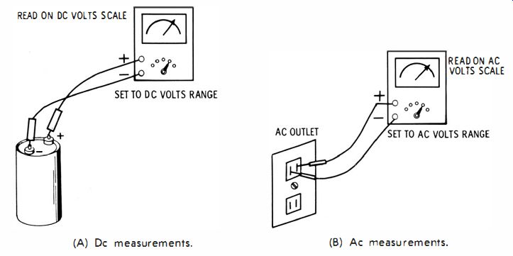
Fig. 4-3. Dc and ac voltage measurements. READ ON DC VOLTS SCALE (A) Dc measurements.
(B) Ac measurements. READ ON AC VOLTS SCALE
DC VOLTAGE MEASUREMENTS
In preparing to make a dc voltage measurement, first be sure that the two test leads are in the proper jacks. Usually, the black test lead should be in the COMMON or minus (- ) jack; and, in most VOM's, the red test lead should be plugged into the plus (+) or VOLTS jack. If there is a switch marked VOLTS-AMPS-OHMS or AC/DC, be sure that the switch (or switches) is set to VOLTS and DC. Next, from a schematic or another source, estimate what the voltage to be measured is. Then, with the range switch, select a range that is considerably above this voltage. Turn off the circuit being measured and make sure that no charged capacitors are in the circuit; then connect the test leads across the two points or source of voltage to be measured, as in Fig. 4-3A. Connect the black test lead to the minus side of the circuit and the red test lead to the positive side. Then turn the circuit or equipment on and note the reading. If the pointer appears to be deflecting backwards, either the polarity of the voltage is opposite to what you had assumed, or you have the test leads reversed in the circuit. You must turn off the equipment, reverse the leads, turn it on again, and once more note the reading. If the pointer does not come to rest in the upper 2/3 of the scale, turn the range switch to the next lower voltage position. If the pointer is still below the 2/3 point, move the switch to the next lower setting, and so on. Then, making sure that you are looking at the correct scale for the range you have selected, note the value that the pointer is indicating. For some ranges, the value can be read directly from the scale; for others, it wi11 be necessary to multiply the reading by 10 or 100. For instance, on the 300-volt dc range, if the associated scale is labeled from 0 to 30 and the pointer indicates 25 (Fig. 4-4 ), you are actually reading 250 volts . Similarly, if the same 0 to 30 scale is used for the 0- to 3-volt range and a reading of 25 is obtained, the voltage is actually 2.5 volts.
In many meters, however, there is a printed scale for each of the ranges provided; thus, multiplying, dividing, or interpreting the readings obtained is seldom necessary.
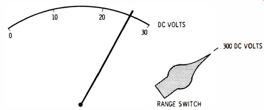
Fig. 4-4. Setting of range switch and position of pointer when measuring 250
volts dc.
Voltage measurements can be made in many cases without turning off the equipment or circuit if the technician has gained sufficient experience to exercise the proper precautions.
AC VOLTAGE MEASUREMENTS
The procedure for making ac voltage measurements is similar to that used for making dc voltage measurements. Begin by making sure the pointer is at zero; plug the black lead into the MINUS jack, the red lead into the PLUS or AC jack; set the AC/ DC switch (if there is one ) to AC, and set the range switch to an ac range somewhat higher than the rms value of the estimated voltage to be measured.
Check to see that the equipment is turned off. Connect the test leads across the points at which the voltage is to be measured, as in Fig. 4-3B; then turn on the equipment and observe the pointer. If there is no deflection or only a little deflection, set the range switch to the next lower range, as required, until the pointer is in the upper 2/3 of the scale.
On many VOM's there may be some difference between the ac scales and the dc scales, so make sure that you use the correct scale or scales for ac. It may be that although the positions of the range switch for dc measurements are the same as those for ac measurements, a different set of scales is provided for each on the meter faceplate. On both ranges, the corresponding markings for the high values may substantially coincide; but for the lower values they may not coincide. Also, a completely separate scale may be provided for the 3-volt or other low ac range. After practice it should be easy to select automatically the proper set of scales for ac or dc measurement.
DC CURRENT MEASUREMENT
For measuring DC current with a VOM, the circuit in which the current is flowing first must be turned off and then opened, such as at point X in Fig. 4-5A. The range switch of the VOM should be set to the current range required. The test leads are then connected in series with the break in the circuit, as shown in Fig. 4-5B, and the equipment turned on. The current is read on the dc voltage scale.
If the meter indicates somewhat below % deflection, the range switch should be set to the next lower current range. If a backward reading is obtained, the test leads should be reversed, or, if a polarity switch is provided, it should be turned to the opposite direction.
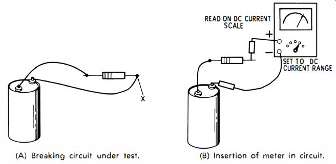
Fig. 4-5. Reading current. (A) Breaking circuit under test. (B) Insertion
of meter in circuit.
When a VOM is set for measuring current, never connect the test leads across a live component or source of voltage; this could burn out the meter movement.
As previously mentioned, most VOM's do not provide for ac current measurement.
MEASUREMENT OF RESISTANCE
To measure resistance, the range switch is rotated to the correct ohms range, depending on the value of the resistance to be measured.
For example, if the ohms midscale value is 5 ohms, and if the estimated value of the resistor being measured is 300 ohms, the range switch should be set to R X 100. If no R X 100 range is provided, the most suitable range is selected to obtain a pointer deflection near midscale.
Before making the resistance measurement, short the tips of the test probes or clips together, and adjust the ohms-zero knob for exactly O-ohms reading at the extreme right of the scale. Next, connect the test probes across the resistor, as shown in Fig. 4-6. When measuring a resistor in a circuit, at least one end of the resistor should be disconnected from that circuit so that other components in the circuit will not affect the resistance value indicated on the VOM. If it is necessary to change the ohms range, the pointer should again be set to zero ohms while touching the probe tips together.
This calibrates the range in use and assures greater accuracy.
The same scale is used for all resistance readings, with the scale values multiplied by 1, 10, 100, 1000, 10,000, etc.; these multipliers are determined by the setting of the range switch. On the higher resistance ranges, touching the ends of the resistor of the test probes with the hands can affect the resistance reading. This is because the body is then connected across the resistor being measured and this parallel resistance lowers the effective value. For high-resistance measurements, touching the resistor or probes should be avoided.
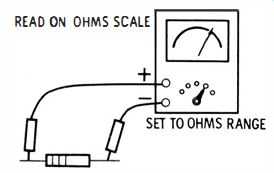
Fig. 4-6. Reading resistance.
READ ON OHMS SCALE
One method of preventing this in resistance measurements is to use clips rather than probes to connect to the resistor, thus permitting you to be entirely free of the measurement.
OUTPUT MEASUREMENT
The output-measurement facility of a VOM is utilized, for example, in measuring the audio output voltage from an amplifier across a speaker, or in measuring the audio output voltage at the input to an amplifier stage. The output measurement is taken in the same way as an ac measurement, except that, if an ac / dc output switch is provided on the VOM, it should be set to output. This inserts a capacitor in series with one of the test leads, which blocks out any dc present in the circuit that is being measured. The associated ac scale is read for the output value.
Sometimes it is desired to interpret the ac output value obtained in terms of decibels (dB). If the VOM includes a dB scale, the value in decibels can be interpreted from that scale. The decibel value depends on the ac range being used. For example, for the VOM of Fig. 3-6, to measure decibels, plug the black test lead into the "-" jack; insert the red test-lead plug into the AF jack; set the selector switch to the 15-V range; connect the black test lead to the ground or common of the circuit; and connect the red test probe to the ac voltage test point.
This particular VOM has been calibrated so that the value of 0 dB is 1 milliwatt on a 600-ohm line. The decibel values are therefore only relative if the measurement is not on a 600-ohm circuit.
QUESTIONS
1. As applied to a VOM, to what does the term "insertion loss" refer?
2. Describe how you would interpret the statement that a particular VOM has an insertion loss of 100 millivolts.
3. As a factor that must be considered, is insertion loss of greater significance in low-, medium-, or high-voltage circuits?
4. What is the approximate accuracy of typical VOM's?
5. At or near which region of the scale is greatest VOM accuracy obtained?
6. If the maximum angle of pointer deflection for a particular VOM is 100 degrees, and if the accuracy rating is ±5%, how might the accuracy of the resistance ranges of the VOM be specified?
7. If the VOM pointer indicates 150 on the resistance scale, and if the range switch is set to R X 100, what is the value of the resistance being measured?
8. How can you easily determine which range to choose when measuring the resistance of a particular resistor?
9. Explain the following example of a specification for a particular VOM: ± 1 dB, 50 Hz to 100kHz, reference 400 Hz.
10. What does the term "repeatability" mean as a VOM specification?
11. What does the term "tracking" mean as a VOM specification?
12. What influence does waveform have on the ability of a VOM to measure accurately?
13. Explain how to zero-set the pointer before using a VOM.
14. Describe how you would set up a VOM for measuring dc voltage.
15. Describe how to measure current with the VOM.