The VOM can be used reliably in practically all general testing, troubleshooting, and maintenance situations, except where unusual accuracy is desired or where unusually high-impedance circuits are being tested. The VOM, itself, rates fairly high in accuracy, but when ever greater accuracy is required, laboratory or precision instruments must be used. For those circuit measurements where the impedance of the circuit is too high for accurate use of the VOM, a VTVM or a solid-state VOM is usually employed. However, as mentioned earlier, some VOM's are available with input impedances which exceed the input impedance of the typical VTVM for certain voltage ranges. Also, in some applications, digital multimeters offer distinct advantages which will become evident later.
APPLICATIONS IN TESTING AND TROUBLESHOOTING
In the first part of this Section, general techniques in applying the VOM and some of the precautions that should be observed will be considered. The remainder of the Section will be devoted to methods for the care, repair, and maintenance of the VOM.
Measuring Capacitor Leakage Resistance
The VOM can be used to advantage in measuring capacitor leakage resistance. For this test, a high-resistance range is employed for example, the R x 10,000 range. When the ohmmeter leads are applied to the terminals of an uncharged capacitor, the pointer will deflect in the direction of zero resistance, and then either slowly or quickly (depending on the capacitor ) the pointer will come to rest at infinity or at a specific amount of resistance. If the capacitor is open, there will be no deflection of the pointer. If the capacitor is shorted, the pointer will indicate zero ohms and remain there. If the leakage resistance is high, the resistance reading will be fairly high compared to the resistance reading obtained from a shorted capacitor.
Generally, the lower the capacitance of the capacitor, the greater the measurable resistance necessary for it to be considered a good capacitor. Mica and paper capacitors of 0.5 u-F to 2.0 u-F should measure 20 megohms or more. Lower-value capacitors should have an even greater resistance. On the R X 10,000 range, most capacitors that have a measurement of infinite ohms probably do not have excessive leakage.

Fig. 5-1. Test-lead polarity for measuring electrolytic-capacitor leakage.
Before the leakage resistance of a capacitor is checked, discharge the capacitor by shorting its leads together. A charged, high value capacitor will discharge through the ohmmeter circuit and slam the pointer against the end-stop, damaging the pointer or the movement.
Electrolytic capacitors will indicate a greater leakage (lower resistance ) than paper, mica, or oil-filled capacitors. The ohmmeter test leads must be connected across the capacitor terminals in the proper polarity. The positive ohmmeter lead should be connected to the positive terminal of an electrolytic capacitor, and the negative ohmmeter lead should be connected to the negative terminal, as shown in Fig. 5-1. Connection in the reverse manner usually results in a very low resistance reading.
Because low-value capacitors have a leakage resistance that is not measurable on a VOM, the best way to check on them-and on any capacitor, for that matter-is to use a capacitor tester. In determining the leakage of a capacitor, this instrument applies the rated voltage to the capacitor.
Measurement of Capacitance
With a VOM The approximate value of a non-electrolytic capacitor can be determined by measuring its reactance with the VOM and a convenient ac voltage source, such as the power line. The VOM, set on the 300-volt ac range, and the capacitor are connected in series and placed across the 110-volt, 60-Hz supply, as shown in Fig. 5-2. The greater the ac voltage reading obtained, the larger the capacitance, assuming that the leakage of the capacitor is low (resistance is high ). For a particular VOM a table or a graph may be prepared relating the ac voltage reading and capacitance by using as standards several capacitors known to be good. Such a table, provided in the instructional manual for the Triplett 630 VOM, is shown in Table 5-1.
The ac voltage readings corresponding to various values of capacitance are shown. The same table would also be useful with other similar VOM's, provided these instruments had a sensitivity of 500 ohms per volt on the ac voltage ranges.
It should be mentioned that this method of measuring capacity is only relatively accurate. A better measurement would be obtained by the use of a capacity checker or an LC bridge.
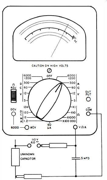
Fig. 5-2. Method of using a VOM to measure capacitance.
Forward-Reverse Rectifier Tests
Relative tests on the condition of copper-oxide, selenium, germanium, silicon, or other solid-state rectifiers can be made with the VOM. The resistance should measure high in one direction and considerably less in the other direction. With the ohmmeter leads connected across the rectifier terminals so that the lesser amount of current flows (reverse direction ), the resistance is approximately 10 times greater than it is with the ohmmeter leads connected across the rectifier terminals in the opposite, or forward direction.
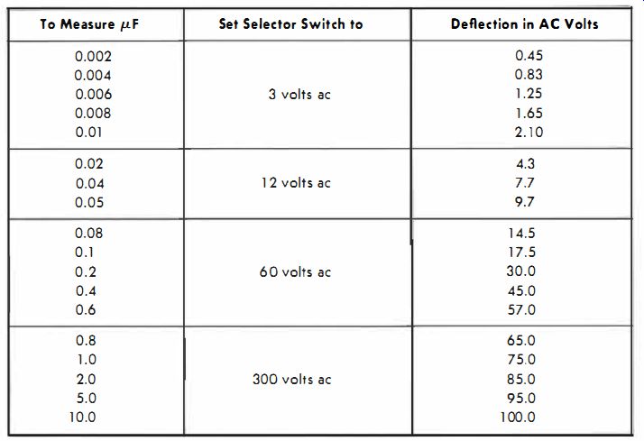
Table 5-1 . Relationship of AC Voltage Readings and Capacitance for Measurement
Arrangement Shown in Fig. 5-2. To Measure uF | Set Selector Switch to | Deflection
in AC Volts
In using this method of measurement, care should be taken that low-current signal diodes are not damaged from the normal current of the ohmmeter circuit; with some diodes this method should not be used. Since the forward and reverse resistances of a rectifier depend to some extent on the voltage applied across it, the results obtained should be considered only relative. However, in most instances a defective rectifier shows up as being shorted, open, or having a reverse-to-forward resistance ratio that is too low. Fairly positive proof is possible by measuring a similar rectifier known to be good and then by comparing the readings obtained to those of the suspected rectifier.
Testing Fused Circuits
One of the most useful applications of the VOM is in testing fuses and fused circuits . The sources of trouble can be located quickly and easily with the VOM. The method of testing a fuse is simple.
The power should be turned off, the fuse removed from the circuit, and the test leads of the VOM, which is set up as an ohmmeter on the R x 1 range, connected across the fuse. The resistance should be zero, or at most only a fraction of an ohm, for the average fuse in good condition.
Sometimes a fuse opens or develops a high-resistance joint only when the higher current of the circuit in which it is used is Rowing through it. In cases when the fuse checks out to be zero ohms by the ohmmeter method but still no power is available to the equipment when it is turned on, a voltage check should be made. This is done, as shown in Fig. 5-3, by setting up the VOM for a 120-volt ac reading. One of the test leads is connected to the un fused side of the line, point 1 (Fig. 5-3). The other test lead is then connected to point 2. The VOM should read the full line voltage if switch S is on.
If the full ac reading is not obtained, the trouble is occurring ahead of the fuse, in either the power switch, the ac line cord, the ac plug, or the ac source. Assuming that the proper ac reading is obtained at point 2 (Fig. 5-3), that test lead is then moved to point 3 (Fig. 5-3 ). If no ac reading is obtained there (or if the ac reading is substantially low), the fuse is probably defective.
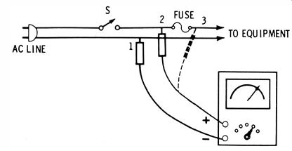
Fig. 5-3. Method for testing fused circuit.
Locating Open Filaments
The VOM is useful also in locating the open filament in a series string vacuum-tube circuit. 'When one tube filament in a series string opens, current is interrupted in all of the tubes in that string. They all go out, and it is impossible to tell by inspection which tube is defective. One method of locating the open tube is to use the ohmmeter section of the VOM to measure across each filament; the filament measuring infinite ohms is the open filament.
An other method is to make a voltage check, as shown in Fig. 5 4A. When the VOM is set up as an ac voltmeter and is connected across a good filament in a series string that contains an open filament, no voltage reading will be indicated. However, the situation is different if the filament circuit is continuous; in that case, the voltmeter will indicate the rated voltage across the filament. In an open circuit, no current flows through the filament; therefore, there is no voltage drop across it to deflect the meter. However, when the VOM is connected across the open filament, the full voltage of the source will be indicated on the meter because the resistance of the VOM is much greater than that of the filament. Therefore, the voltage drop across the meter approaches the applied voltage. The connection of the VOM across the open filament completes the circuit, permitting a small amount of current to flow and, thus, to deflect the meter. This is not an effective test if two tubes in the string have open filaments. In such a case there will be no voltage reading on any tube in the series string as the VOM is moved from tube to tube.
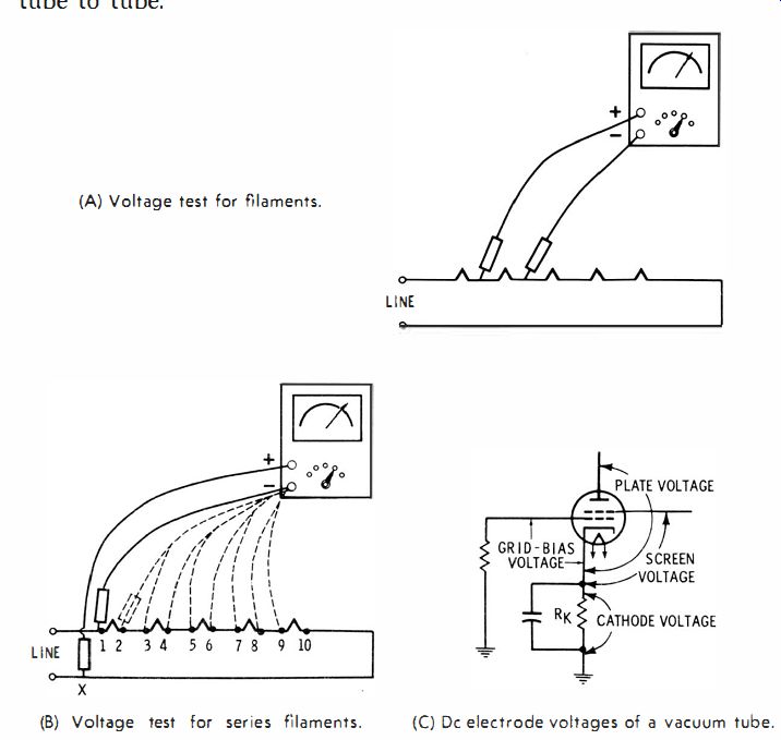
Fig. 5-4. Measurement of tube-element voltages. (A) Voltage test for filaments.
(B) Voltage test for series filaments. (C) Dc electrode voltages of a vacuum
tube.
A more common and more reliable method is shown in Fig. 5-4B. The meter, set on an ac range that will handle the full line voltage, is connected with one lead to the common side of the line at point X, Fig. 5-4B. The other lead is then moved progressively from point 1 through points 2, 3, 4, 5, 6, etc., getting a slightly lower voltage reading at each tube. If a point is reached where zero voltage is indicated, the tube at that point has an open filament. Replace this tube and proceed to the next filament test points toward the common end of the series string in the same manner. Always work from the beginning of the series toward the end, replacing tubes that have open filaments. The last tube in the string may be checked by the method shown in Fig. 5-4A, since the normal voltage between point 10 and point X is zero.
Testing Electronic Circuits
The dc voltages for the electrodes of a vacuum tube are measured as shown in Fig. 5-4C. Plate voltage is measured between plate and cathode, screen voltage between screen grid and cathode, grid-bias voltage between control grid and cathode, and cathode voltage between cathode and ground (or across the cathode resistor, RK )' Although these are the true dc operating voltages for a vacuum tube, in many cases the voltage lists accompanying the schematic for an electronic device are designated as being measured between the particular tube electrode and the ground or chassis. This reference to ground for each of the voltages is for convenience in measurement; it permits leaving the negative, or common, lead connected to the chassis for each measurement.
Many schematics list the resistance readings between various tube pins and ground. Any serious discrepancy between the resistance listed and the measured resistance is an indication of trouble in one or more of the components common to that circuit.
Quick Check of Transistors
A quick-check method of testing for shorted or open bipolar transistors is shown in Fig. 5-5. This method, which is provided with the RCA WV-529A VOM shown earlier, is carried out as follows :
1. Connect the test leads to the transistor elements as shown in the illustration. Set the polarity switch on the meter to pos and measure the base-to-emitter resistance, then the base-to-collector resistance. Both readings should be about the same.
2. Set the polarity switch to NEG and again measure the base-to-emitter and base-to-collector resistances. These two measurements should also be about the same (but different from those obtained in Step 1) .
3. The readings obtained should be low (about 500 ohms ) for one step and high (about 500K) for the other step, depending upon the polarity of the transistor (npn or pnp). If any of the four individual measurements are radically incorrect, the transistor is bad.
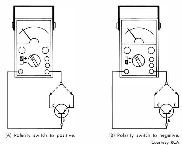
Fig. 5-5. Method of quick testing for shorted or open transistors. (A) Polarity
switch to positive. (B) Polarity switch to negative.
Testing Batteries
The VOM is useful for testing the condition of batteries. It should always be remembered that it is best to measure the output voltage of a battery when the battery is under load or actually being used in the equipment. As a battery deteriorates or becomes discharged, its internal resistance increases. The load current flowing through this internal resistance reduces the output voltage appearing across the battery terminals. If the load current is not flowing (as when the battery is tested out of the circuit ), the voltage is not reduced by the internal resistance and the battery may test good. In many cases, badly deteriorated batteries measure low in voltage even when removed from the circuit. Any battery that measures 75% or less of rated voltage under load is considered weak and should be either charged or replaced, depending on the type of battery.
The VOM is very useful for checking the operation of automobile batteries. In many cases, a poor connection due to dirt or corrosion develops between a battery terminal and the clamp or lug fastened to it. When a battery measures full output voltage across its terminals, but poor starting or other electrical troubles are experienced, measure the battery output voltage across the lugs fastened to the battery terminals, and then measure across the terminals themselves.
If the voltage measured across both points is not the same, poor electrical contact exists between one terminal and its associated lug.
The connection that is involved can be determined by measuring for a voltage difference across the contact points. To do this, place one test lead on the battery terminal and the other lead on the lug connected to the terminal (Fig. 5-6). Any measurable voltage drop is a sufficient reason to remove and clean the connection to correct the difficulty.
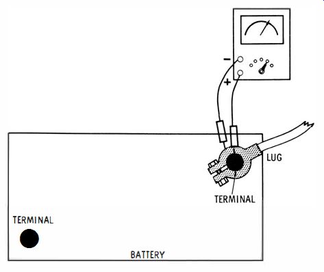
Fig. 5-6. Measuring voltage drop across battery connections.
Measurements in Sensitive Circuits
In some cases, connecting a VOM to a sensitive, high-gain or sharply tuned circuit upsets the operation of the circuit being tested so that the reading obtained is not representative of actual operating conditions. Measurement in such circuits is best made with an instrument that has a higher-resistance input. If this equipment is not available, the next best approach is to use a resistor in series with the positive test lead of the VOM as shown in Fig. 5-7. The series resistor that is selected should have a value higher than the impedance of the circuit being measured. With the use of the series resistor, the reading will not be as accurate, but often only a relative reading is required.
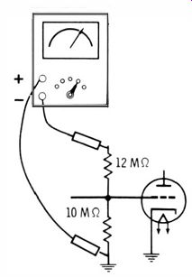
Fig. 5-7. Use of a high-value resistor in series with test lead for sensitive
circuits.
Where accuracy is important, the reduction due to the series resistor may be calculated. The series resistor and the resistance of the VOM on the scale employed may be considered to be a voltage divider. For example, assume that a voltage is to be measured across a 10-megohm circuit and that the series resistor selected is 12 megohms. If the 300-volt dc range on a 20,000-ohms-per-volt VOM is employed, the meter resistance is then 300 x 20,000 = 6 megohms. The voltage divider is then a 12-megohm resistor in series with a 6-megohm resistor, with the measurement occurring across the 6-megohm resistor. With the total resistance being 18 megohms, only 1/3 of the voltage is read by the meter; therefore, the reading obtained should be multiplied by 3.
The manufacturer of the RCA WV38A VOM provides the following table in the instruction manual, listing the multiplier and the reading for specific values of series resistance (Table 5-2). Table 5-2. Readings Obtained Using Series Resistors to Decrease Loading Effect
PRECAUTIONS
Caution is essential when working on, or making measurements on electrical and electronic equipment. You should always be alert to the possibility that the same cause of faulty operation might also cause dangerous high voltage to be present at places least expected.
A good practice is to work with one hand behind you or in your pocket. This gives some protection against contacting points of potential difference. Be sure to avoid standing on conductive, damp or wet surfaces when making measurements; if possible, stand on a dry board. Try to stand clear of the equipment so that other points on your body do not touch the equipment when you are connecting or disconnecting a test lead.
When making resistance measurements, be sure the power is off and that all capacitors that might hold a charge have been discharged by shorting across their terminals with an insulated test lead or a screwdriver having an insulated handle.
Sequence of Test-Lead Connection
When connecting the VOM to a circuit for a voltage measurement, first the common (usually negative) lead should be connected to the chassis of the equipment on which the measurement is being made; then the positive test lead is connected. Fig. 5-8 illustrates what may happen if this practice is ignored. Note that in Fig. 5-8 the positive, or red, test lead is connected to the positive voltage point. If you then happen to hold or touch the tip of the negative test probe and, at the same time, with your other hand touch the chassis (to which the negative lead of the meter is to be connected ), practically the full voltage existing across the positive and negative points of the equipment under test will be impressed across your body and the meter. The resistance of the body, normally fairly high, in series with the VOM, receives a high percentage of the voltage.
For the reason just mentioned, when test leads are disconnected, the positive, or high-potential, lead should be disconnected first; the negative, or low-potential, lead should be disconnected last.
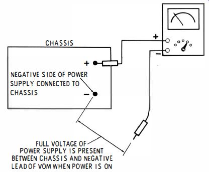
Fig. 5-8. Shock danger of improper sequence of connecting test leads.
Determining if a Chassis Is "Hot"
"Hot-chassis" receivers are receivers in which one side of the ac input is connected to the chassis. If the set is connected to the ac output so that the ungrounded side of the ac power line is the one to the receiver chassis, it is possible to receive a dangerous shock by touching the receiver chassis and some ground point at the same time.
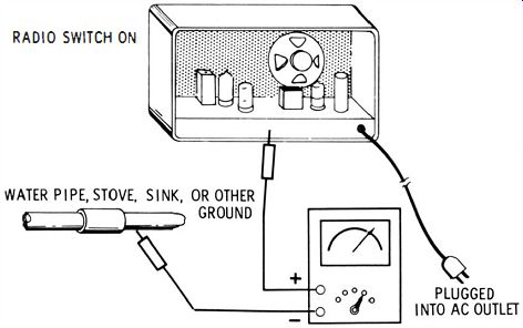
Fig. 5-9. Using a VOM to check "hot-chassis" equipment for presence
of shock hazard.
The VOM can be employed to determine whether or not the receiver chassis is hot relative to ground. Set up the VOM to measure 120 volts ac, as shown in Fig. 5-9. Connect one test lead to a ground point, such as a water pipe, radiator, or electric-stove frame, and connect the other test lead to the receiver chassis. If the VOM reads the full line voltage, or even more than a very few volts, the danger of shock exists. To correct this condition, remove the ac power plug from the wall outlet, rotate it 1800, and reinsert it in the wall outlet. Again use the VOM to measure between chassis and ground. There should now be no measurable voltage, and the receiver is safer to work on.
Test-Lead Inspection
Test leads should be inspected regularly for broken or frayed leads that could present a shock hazard to the user. Replace or repair such test leads immediately. After a VOM test is completed, it should always be disconnected from the circuit immediately; otherwise there is a good possibility you or some other person might unknowingly pick up the VOM and test leads and either receive a bad shock or cause a short in the equipment to which the leads are connected.
It is good practice when working on equipment in which more than 40 or 50 volts exist, to have someone nearby in case you do receive a serious shock.
Finally, never make measurements with a VOM that has been removed from its case.
CARE AND MAINTENANCE
Manufacturers make VOM's as rugged as possible for a delicate instrument, but there is a limit to the abuse an instrument of high sensitivity can withstand.
Care in Selecting Range
It was mentioned earlier, but it is worth repeating, that for current and voltage measurements, always begin with a range higher than the voltage or current expected. This will provide some assurance that the meter will be protected if the voltage or current is excessive.
Double-check before connecting the test leads. If the range switch is accidentally left in the OHMS position or on a low range, one or more components of the meter movement (a pretty expensive item ) may be destroyed.
Protection From Physical Damage
Always store the VOM where it will not fall or accidentally be knocked down; even if the meter cabinet does not break, the pivot of the pointer may be jarred from its bearings. Replacing or repairing any part of the meter movement is usually a job for a specially trained technician. It is usually necessary to return the instrument to the factory for repair and recalibration. Never place the VOM on a workbench where power tools are used or where excessive vibration is present. Avoid having the VOM where metal chips or metallic dust is present; if these get inside the case of the instrument, a short or other trouble may develop. Do not place the VOM where excessively high or low temperatures are likely to occur or where excessive moisture or dampness may cause leakage between components, wires, or switch contacts, or cause deterioration of the batteries.
REMOVAL FROM CASE
On some occasions it is necessary to remove the VOM from the case-at least to change the batteries. These get weak after long usage. The first and most obvious sign of aging batteries is that it becomes impossible to bring the pointer to zero in the resistance range, with the test leads shorted together. There is usually some movement of the pointer, even with weak batteries.
For the lower-resistance ranges, usually one or two 1.5-volt dry cells are active in the circuit. For the higher-resistance ranges, such as R X 10,000 or R X 100,000, higher-voltage (but usually not physically larger ) batteries of 4.5 volts, 7.5 volts, 33 volts, 67.5 volts, etc., are sometimes utilized. Therefore, it is possible that the VOM may zero on one or two of the ranges but not on the others. This evidence will show which battery or batteries to replace.
To remove the VOM from its case, it is generally necessary only to remove two to five screws from the back or bottom of the case.
These may be either slotted-head screws or Phillips-head screws.
In most cases, after the screws are removed, merely lift the case from the instrument. If the back of the case does not come free easily, do not try to shake it free without holding the other part of the case with your other hand.
The batteries usually are held in place by a spring-type holder, and they should not be difficult to remove. All that is usually necessary is to lift them out of the holder and slide in the new battery. Before putting in the new battery or batteries, look at the metal contacts to see if rust or corrosion has started to appear; if so, clean or scrape the contacts. Try to keep the particles from falling into the instrument--if necessary, use a vacuum to remove any that may fall into it.
Batteries should be replaced with similar types. However, for some batteries there are long-life, industrial, or instrument versions for replacement that might give longer satisfactory performance than the type provided with your VOM. The leakproof type of battery should be used, which will help prevent the battery chemicals from damaging delicate or precision components. Batteries should be inserted with the proper regard to polarity; the battery holders are almost always marked, one side + and the other -, to correspond to the terminals of the battery.
Fuse Replacement Should the fuse in the VOM blow, it should be replaced only by an identical fuse. If the fuse is one with a conventional element, it should never be replaced by a slow-blow type of fuse; this reduces the margin of protection to the meter movement. A fuse in a typical VOM will be a 1-ampere, 250-volt type; fuses of other ratings may also be encountered in some meters . If the VOM fails to respond on all foundations, it is possible that either the fuse is open, one of the test leads is open, or there is a break in the wiring to one of the jacks. The meter movement may be defective if there is no response on any function.
Testing the Meter Movement
If it is suspected that the meter movement is defective, do not attempt to repair it yourself; this almost always leads to added damage to the movement. Instead, follow the manufacturer's directions in the VOM instruction manual, and return it to him. Some manufacturers request that you write first, to obtain a "return authorization." Whatever the instructions, follow them closely in order to prevent the meter from becoming lost.
Do not attempt to measure the resistance of a meter movement with another VOM, since the batteries in the second VOM will probably cause excessive current through the meter.
One way to check the meter movement, if care is used, is as follows : Remove all connections from the terminals on the back of the movement case. Wire a circuit consisting of a l.5-volt battery and a series resistor for connection to the meter terminals (Fig. 5- 10 ). Fig. 5-10. Method for testing meter movement.
Calculate the value necessary for the series resistor to provide about 2/3 full-scale deflection. For example, if the movement is a 50-microampere, 250-millivolt type, % of the full-scale current is about 33 microamperes . The total circuit resistance must be 33
?·?0
-6
= 45,000 ohms (approximately ).
The meter has a resistance of 50 ??O 6 = 5000 ohms.
The required value of the series resistor is then 45,000 - 5000 = 40,000 ohms (39,000 ohms is the nearest standard value ). If no deflection is obtained, or if it is substantially different from % of full scale, the movement is probably defective.
Rectifier Replacement
Should the meter fail to work properly on the ac ranges, it is likely the rectifier is defective. An exact-replacement rectifier should be used. If two rectifiers are used in the VOM, you should replace both, using a properly matched set obtained from the manufacturer or authorized distributor. Substitution of a rectifier that is almost, but not quite, the same will result in inaccuracy on the ac ranges.
Resistor Replacement
If you have the misfortune to try to measure voltage when your VOM is set to measure ohms, it is possible that one of the resistors in the ohmmeter circuit will open and will have to be replaced. Be sure to replace the resistor with an identical type. If the identical replacement is not available, and if the VOM must be used before one can be obtained from the manufacturer, a resistor of identical characteristics--the same value, tolerance, wattage, and composition--can be used.
Calibration of a VOM
The accuracy of a VOM can be checked to a sufficient approximation by measuring a battery known to be good. New dry cells should measure about 1.55 volts per cell. The resistance ranges can be checked by measurement of a precision resistor known to be good. The VOMs also can be compared with another instrument known to be accurate.
In some VOM's little can be done, other than to change parts, if it is discovered that the accuracy is off. Other VOM's include calibration adjustments for this purpose. Ordinarily these should not be touched. However, if components are replaced, especially the rectifier, it is sometimes necessary to adjust these calibration controls closely following the directions of the manufacturer.
Soldering
Connections in a VOM In replacing components or resoldering connections, avoid over
heating nearby parts; this may change their value. Use a thin-tipped 25- to 40-watt soldering iron. It is important also to use only rosin core solder; never use acid-core solder.
Many VOM's now in use employ printed-circuit boards. Always closely follow the directions of the manufacturer when removing, repairing, or replacing the board and when soldering or un soldering connections or components.
QUESTIONS
1. How can you use the VOM for measurement of capacitor leakage resistance?
2. What is the typical leakage resistance for a paper or a mica capacitor of about 0.5 uF?
3. What is the typical leakage resistance of electrolytic capacitors?
4. How do you measure the forward-reverse resistance of a selenium or a silicon rectifier?
5. How can you use the VOM to tell if a fuse is blown?
6. Explain how to use the VOM as a voltmeter for locating a tube having an open filament in a series-string circuit.
7. Discuss using the VOM for testing battery condition.
8. If connection of a VOM upsets the operation of a sensitive, high-gain, sharply tuned circuit, how can this effect be reduced?
9. What are some of the safety precautions that should be followed when measurements are made on electrical and electronic equipment?
10. How can you tell if a chassis is "hot"?
11 . How can you check a meter movement to see if it is defective?
12. If a VOM works on the dc ranges but not on the ac ranges, what is the likely source of the problem?
13. If the rectifier in a VOM is defective, what kind of replacement can be used?
14. Discuss the care that should be used when repairing a VOM.