The main difference between the VOM and an electronic analog meter, such as the VTVM (vacuum-tube voltmeter ), the transistorized voltmeter, or the FET (field-effect transistor ) meter, is that the electronic type of VOM includes one or more amplifier stages to increase the amplitude of the quantity being measured. There are other differences also; some are advantages, and some are disadvantages. The first type of electronic VOM to be considered is the VTVM.
An important part of the operating principles of the VTVM and other electronic VOM's is the same as that of the standard VOM. That is, current flowing through a d'Arsonval meter movement causes deflection of a pointer in proportion to the intensity of the current.
Vacuum-tube voltmeters are also much like VOM's in appearance.
Examples are shown in Figs. 6-1 and 6-2. The unit in Fig. 6-1 is a typical instrument of moderate cost and good performance; the one in Fig. 6-2 is of more elaborate design and is somewhat more costly.
Instruments between these two limits of price and performance are representative of meters used widely in measuring, testing, troubleshooting, and experimenting.
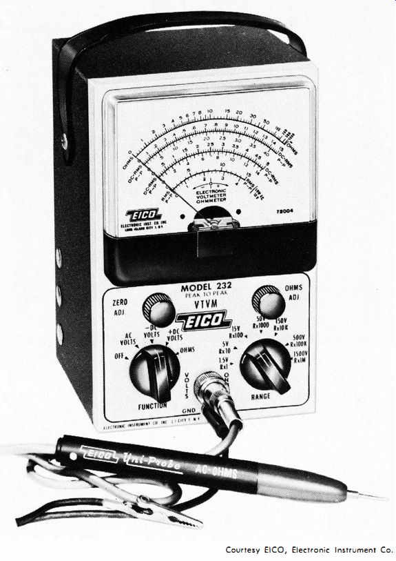
Fig. 6-1. EICO Model 232 VTVM.
In addition to commercially built VTVM's, there are kit types that the purchaser can build from parts provided by the manufacturer.
An example is shown in Fig. 6-3. Assembling a kit can save the purchaser a good percentage of the cost of a VTVM if he has the time to assemble it. Assuming that the directions are followed carefully for assembly and calibration, and that good soldering practices are employed, a kit VTVM can approach the best commercial models in performance.
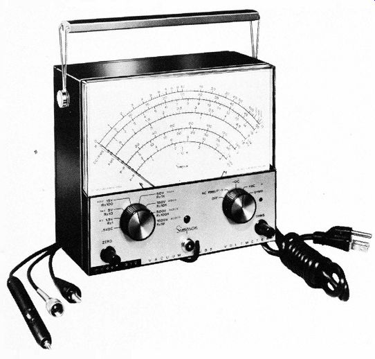
Fig. 6-2. Simpson Model 312 VTVM.
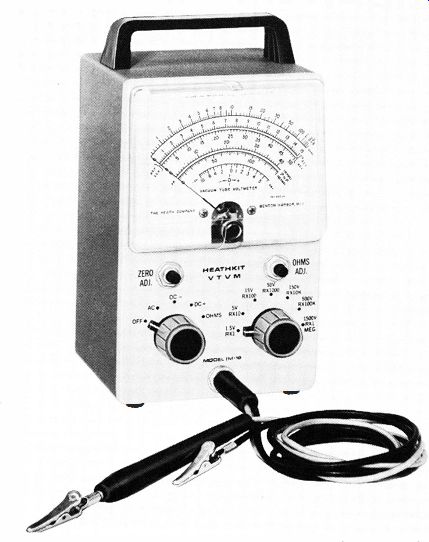
Fig. 6-3. Heath Model IM.1 8 VTVM.
ADVANTAGES AND DISADVANTAGES OF THE VTVM
The major difference between the VOM and the VTVM is that in the VTVM one or more vacuum tubes are employed in the circuit. This has the following advantages, as compared with the VOM:
1. Higher input resistance.
2. Lower input capacitance.
3. Greater sensitivity.
4. The use of less-sensitive, lower-cost meter movement.
The higher input resistance permits measurement in circuits having high impedance or resistance with less loading effect than with the typical VOM. The lower input capacitance of the VTVM makes possible measurement of ac voltage at higher frequencies than are possible with the VOM. The greater sensitivity of the VTVM, provided by one or more stages of amplification, makes possible the measurement of lower values of voltage and higher values of resistance. The use of the less-sensitive, lower-cost meter movement is made possible by the amplification provided in the VTVM circuit.
These advantages are of sufficient importance, in many cases, to overlook some of the following disadvantages of the VTVM:
1. The VTVM is less stable than the VOM; the VTVM requires warmup time for reasonable accuracy.
2. It must be calibrated more frequently.
3. An external source of power is usually required.
4. The more complex circuitry is subject to more-frequent trouble.
The reason for some of these advantages and disadvantages will become apparent later when the basic and typical circuits of VTVM's are discussed.
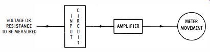
Fig. 6-4. Block diagram of a VTVM circuit.
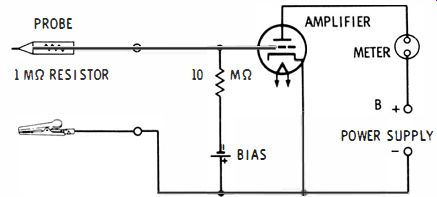
Fig. 6-5. Schematic of a basic VTVM circuit.
VTVM PRINCIPLE
Basically, the VTVM consists of an input circuit, an amplifier, and a meter movement, as shown in Fig. 6-4. It is because a vacuum-tube amplifier has a high input resistance that a VTVM causes less loading when it is connected to a circuit for voltage measurement. On most of the voltage ranges, the input resistance for typical VTVM's is 10 or 11 megohms or more.
Simple VTVM The simplest type of VTVM for measuring dc voltages is shown in Fig. 6-5. The I-megohm resistor built into the probe is mainly responsible for minimizing the VTVM input capacitance, or capacitive loading effect. It serves to isolate the VTVM circuits from the circuit being measured. The input resistance of this VTVM circuit consists of the I-megohm probe resistor and the IO-megohm grid resistor, a total of 11 megohms. The battery provides a bias for the triode amplifier tube, keeping it at cutoff until the test leads are placed across a positive or an ac source of voltage.
If the voltage being measured is dc, the positive voltage contacted by the probe lowers the bias on the amplifier grid and causes current to flow through the tube and meter movement in proportion to the amplitude of the positive voltage.
If the voltage being measured is ac, the negative half cycles of the ac voltage have no effect on the amplifier and meter current, since the amplifier is biased at cutoff and the negative ac alternations will increase the bias even further. On positive half cycles, however, amplifier current will flow, the average amount of current causing a proportional deflection of the meter pointer.
It is not practical to use this simple triode circuit in VTVM's, however, mainly because if the voltage to be measured exceeded the bias voltage, the grid would draw current, loading the circuit under test, and resulting in an inaccurate indication on the meter. Another reason is that the probe may be connected only to a positive voltage; this means that there is no provision for measuring negative voltage.
Practical VTVM Circuit
The basic circuit used in many VTVM's is shown in Fig. 6-6. The arrangement in Fig. 6-6A is for measurement of positive voltage. The circuit in Fig. 6-6B (the same as the one in Fig. 6-6A except for the point to which the probe is connected ) is for measurement of negative voltage.
The basic vacuum-tube voltmeter circuits of Fig. 6-6 are known as bridge circuits-the meter movement is "bridged" between the plates of two identical vacuum-tube circuits. Suppose no voltage is being measured; the grids of V1 and V2 are at the same potential with no grid voltage applied to Vi. Under this condition the currents through the tubes are equal and their plates are at the same potential. With the same potential at each side of the meter, no current flows through the meter, so the pointer indicates zero. If it does not indicate zero, the ZERO ADJUST control is adjusted so that the indication is zero.
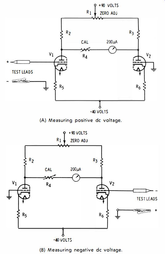
Fig. 6-6. Practical amplifier circuits for a VTVM. (A) Measuring positive
DC voltage. (B) Measuring negative DC voltage.
VTVM DC VOLTAGE MEASUREMENT
When the test leads in Fig. 6-6A are connected across a source of voltage, with the probe connected to the more positive point, the current through V1 increases, causing a voltage drop in R2, and thus decreasing the voltage on the left side of the meter movement. With the right side of the meter now more positive than the left, current flows through the meter, its value being proportional to the voltage applied to the grid of V1. The current in V2 does not change, since its grid is grounded. The calibration (CAL ) control in series with the meter is not an operating control; it is adjusted only at the time of calibration of the meter for exact indication of the pointer.
For measurement of negative voltage, a switching circuit in the VTVM usually transfers the test leads to the opposite triode, V2, and grounds the grid of triode V1, as shown in Fig. 6-6B. Now, with a negative voltage on the probe tip, the current in V2 decreases, the voltage at the right side of the meter increases, and current again flows through the meter in the same direction as that for the circuit in Fig. 6-6A. As is shown in the schematic, the voltage being measured is applied to the input of each of the vacuum tubes, not to the meter itself. Thus, the meter is isolated from the circuit under test and is relatively safe from damage due to overload.
VTVM MEASUREMENT OF AC VOLTAGE
For the measurement of ac voltage, the same circuit of Fig. 6-6 is used but is preceded by a rectifier circuit (Fig. 6-7 A). When ac voltage at the probe swings positive, diode V conducts through resistance R, at the same time charging capacitor C2 to the peak value of the ac input voltage. Resistor R is of high value, so C2 does not discharge completely before the next positive half cycle charges it again. The voltage to the grid of the bridge amplifier is approximately equal to the peak value of the ac input voltage.
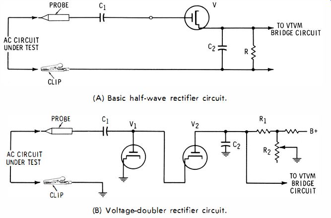
Fig. 6-7. VTVM rectifier circuits for ac voltage measurement. (A) Basic half-wave
rectifier circuit. (B) Voltage-doubler rectifier circuit.
Often the rectifier for ac voltage measurement in a VTVM is a twin
diode voltage-doubler rectifier, similar to that shown in Fig. 6-7B. When the ac input voltage goes positive, capacitor C1 charges through diode V1 to the peak value of the positive voltage. As the ac voltage swings through zero toward negative, V1 stops conducting; C1 remains charged to the peak voltage since it has no discharge path. With the input signal now negative, C1 discharges through diode V2 which conducts through C2. The charging voltage for C2 is now the sum of the input voltage and that of Ct, or the total of the positive and negative peaks. Thus, the rectifier circuit provides the grid or input of the bridge circuit with a peak-to-peak voltage for the deflection of the meter movement. The scale, however, will be calibrated in terms of rms for a sine-wave voltage and, sometimes, for peak and peak-to-peak values. Potentiometer R2 permits adjustment for zero deflection of the pointer when a zero-volt input is applied.
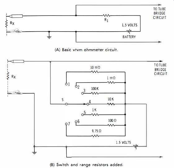
Fig. 6-8. VTVM resistance-measuring circuits. (A) Basic VTVM ohmmeter circuit.
(B) Switch and range resistors added.
VTVM RESISTANCE MEASUREMENT
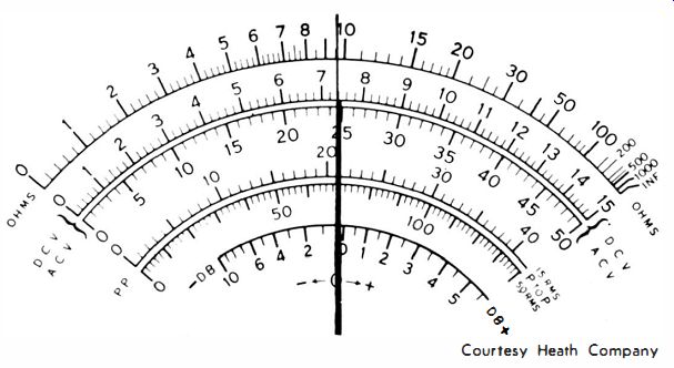
Fig. 6-9. Example of VTVM meter faceplate to illustrate differences from the
VOM.
For measurement of resistance, the input circuit to the VTVM bridge is basically that shown in Fig. 6-8A. When the test leads are shorted together, there will be no deflection of the pointer-a zero ohms calibration control (not shown here ) is adjusted for O-ohms reading. Then, with the test leads open, the 1.5-volt battery in series with R1 is across the input circuit, and the meter is deflected full scale (adjusted exactly by means of an OHMS ADJUST control, not shown here ). When the test leads are then connected across an unknown resistor, R" the deflection of the pointer will be in proportion to the value of Rx. Thus, in the VTVM, as is apparent on the OHMS scale of the VTVM faceplate of Fig. 6-9, the greater the resistance, the greater is the deflection. This is opposite to the effect in the VOM, where deflection of the pointer is less when the resistance value of the unknown resistance is increased.
In Fig. 6-5A, when the unknown resistance has the same value as R1, the deflection is midscale, since R1 and Rx then form a 2:1 voltage divider that applies half the battery voltage to the input circuit of the bridge.
Shown in Fig. 6-5B is the same circuit, but with a switch and additional resistors added for providing seven resistance-measurement ranges. In position 1 of switch S, the midscale reading of the VTVM is 10 megohms; in position 2, the midscale reading is 1 megohm; in position 3 it is 100K, and so on to the lowest range.
VTVM CURRENT MEASUREMENT
The facility to measure current is not usually provided in a VTVM, although some models do include this facility. One of the advantages of the VTVM is that a less-sensitive meter movement may be used; another is that the meter movement is relatively safe from accidental overload. The occasional VTVM that is designed for current measurement cannot usually measure currents as low as the typical VOM. The chance for damage to the meter movement increases greatly when the facility for current measurement is added; however, the use of zener diodes and other protective circuits or devices greatly reduces this hazard.
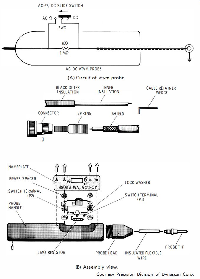
Fig. 6-10. Probe for measurement of ac, dc, and ohms. (A) Circuit of VTVM
probe. (B) Assembly view. Courtesy Precision Division of Dynascan Corp.
VTVM PROBES
The basic probe for most VTVM's is as previously described. For dc voltage measurement it consists of a housing that contains a 1-megohm resistor in series with the test lead. The 1-megohm series resistor is not used for the measurement of ac voltage or for the measurement of resistance. For these functions, either a different probe is used or a switch built into the probe allows for shorting out the I-megohm resistor. The circuit of a typical probe is shown in Fig. 6-10A, with the switch in the dc-volts position (1-megohm resistor in the circuit ). In the opposite position of the switch, used for ac and ohms, the I-megohm resistor is shorted out. An assembly view of this probe is shown in Fig. 6-10B. A coaxial connector is used for connecting the shielded lead of the probe to the VTVM.
For the measurement of high-frequency ac voltage, an additional probe that is called an rf probe may be utilized with a VTVM. In an rf probe, a diode is built directly into the probe. In this way, capacitive loading from the VTVM on the circuit under test is kept at a minimum; also the VTVM is able to measure a higher frequency range since the output from the probe diode is dc voltage. Therefore, the capacitance of the cable and the VTVM input circuit have no reactive attenuating effect on the signal being measured.
The VTVM, like the VOM, can also be used to measure voltages greater than those for which it was basically designed. This is done by means of a high-voltage multiplier probe, the same as the VOM high-voltage probe described earlier. Because of the higher average input resistance of the VTVM, a VTVM high-voltage probe has considerably less loading effect on a high-resistance, high-voltage circuit than does the VOM high-voltage probe.
For a VTVM having an 11-megohm resistance, the value of the series multiplier resistor, which is in the handle of the high-voltage probe, is 1089 megohms for a 100:1 voltage reduction. The 1089 megohms adds to the 11-megohm input resistance of the VTVM, giving a voltage divider having 1100 megohms of total input resistance. The input to the 11-megohm VTVM measuring circuit is 1/ 100 of the high voltage being measured. The probe may be used on any of the VTVM voltage ranges where the input resistance is 11 megohms.
RESPONSE OF THE VTVM
The VTVM has a wider frequency response than the VOM. A typical VTVM with general-purpose probes provides a flat response within 1 dB or so from 20 or 30 Hz to 3 or 4 MHz or more. With an rf probe, the response can be extended to 250 MHz or more. For some laboratory VTVM's, this response extends to 1000 MHz.
TYPICAL VTVM CIRCUIT
At this point a brief examination of an actual VTVM circuit will help unite the basic concepts previously covered and will give a better overall understanding of the operation of the VTVM. The VTVM we shall consider here is the B & K Precision Model 177 shown in Fig. 6-11; the schematic is shown in Fig. 6-12. This circuit is typical of the popular VTVM's.
The input to the VTVM is provided by means of a common-purpose probe which includes a I-megohm resistor as previously described. In the probe circuit (lower-left center ), the slide switch is shown in the dc position.
The 100-microampere meter movement, located in the center of the schematic, is connected in the plate circuit of the l2A U7 twin triode in a balanced bridge arrangement. The ZERO ADJ control sets up a balance between the two triodes so that with zero volts applied to the first grid, potentials on each plate are equal. Since there will then be no voltage drop across the meter, the meter will read zero.
With a voltage applied to the first grid, the balanced condition is upset, a difference in potentials on the two plates (and across the meter ) results, and there will be an indication on the meter. Since there will be a linear relationship between the measured voltage applied to the first grid and the current through the meter, the meter scale is calibrated with linear markings.
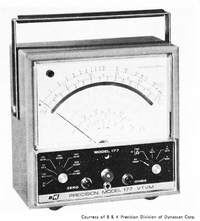
Fig. 6·1 1. B & K Precision Model 177 VTVM.
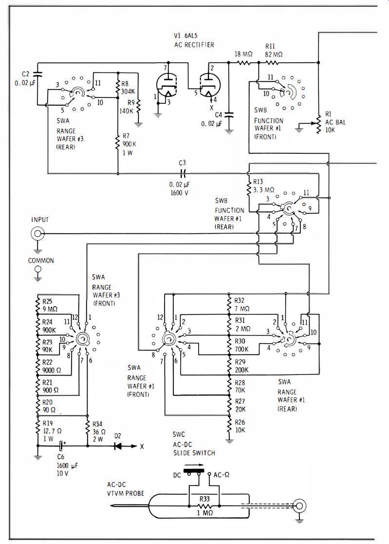
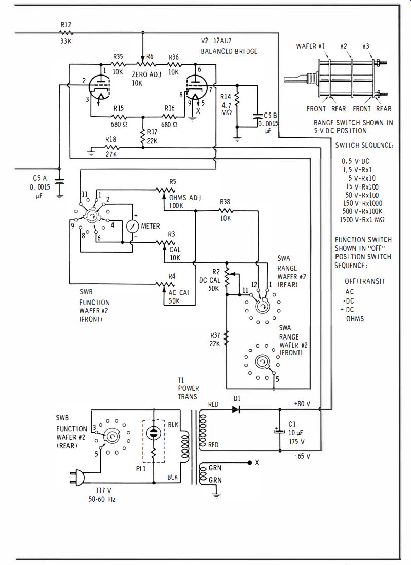
Fig. 6-12. Circuit diagram of B & K Model 117 VTVM. Courtesy of B & K
Precision Division of Dynascan Corp.
The maximum voltage ever applied to the 12AU7 is approximately 1.5 volts. The voltage divider at the input, consisting of R21 through R2S, has a total resistance of approximately 10 megohms.
For ac measurements, a 6ALS duo-diode is used to rectify the test voltages providing a dc voltage proportional to the applied ac. The dc voltage is then applied through the voltage divider network to the input grid of the 12AU7 balanced bridge circuit, causing the meter to indicate. The 6ALS is connected as a half-wave doubler which will respond to the peak-to-peak value of applied ac test voltages. The ac voltage scales are calibrated to read both rms and peak-to-peak values. The 0- to 1.5-V and 0- to 5.0-V rms low ac scales have been especially calibrated to improve the accuracy of the meter on these low ranges. Stray pickup reduces the accuracy of any highly sensitive VTVM on the lower ac ranges. In the 0- to 1.5-, 0- to 5, 0- to 50-, and 0- to 150-volt ranges the full ac voltage being measured is applied to the 6ALS rectifier. A voltage-divider network reduces the voltage on the 0 to 500 and 0 to 1500 voltage ranges to limit the voltage applied to the 6ALS to a safe level. With proper use of the instrument, the input voltage to the 6ALS is always 150 volts or less ; care should be taken that this value is not exceeded. Developing the habit of starting out with the range switch in the highest position, then working down to the appropriate lower one will result in protection to the instrument. If 400 volts or more is applied to the 6ALS, damage to the tube will probably result.
The ac balance control is used to compensate for the contact potential developed on the 6ALS. A diode tube, with its filament heated, conducts a small amount even though no voltages are applied to plate or cathode. This current Rows from cathode to plate of the diode, through the external resistors to ground, and back to the cathode. The voltage developed across the resistors will be negative with respect to ground and is known as contact potential. To offset this negative voltage, an equal positive voltage is taken from the power supply and fed into the circuit. The amount of "bucking" voltage is controlled by the ac balance control. This minimizes movement of the pointer when switching from one low ac range to another. The ac calibration control is used to obtain the correct meter deflection for the ac voltage being measured.
For measuring resistances, a 1.5-volt dc supply is connected through a series of multiplier resistances and the external resistance to be measured. This forms a voltage-divider circuit consisting of the 1.5-volt supply in series with one or more multiplier resistors and the resistance under test. The voltage across the unknown resistor is then proportional to its resistance and is applied to the input grid of the 12AU7 balanced bridge circuit which produces an ohmmeter-scale reading proportional to the unknown resistance.
In the OFF position, the meter movement is automatically shorted to prevent damage in transit.
The VTVM is powered by ac voltage for the filaments and by dc voltage derived from the power transformer and the solid-state rectifier, D1. In some older instruments, vacuum-tube rectifiers were employed; most modern instruments now employ either silicon or selenium rectifiers.
QUESTIONS
1. What are the major important differences between the VOM and the VTVM?
2. What are some of the disadvantages of the VTVM, compared to the VOM?
3. Sketch a schematic of a basic VTVM circuit.
4. Describe the VTVM "bridge" circuit.
5. Of what does a typical VTVM probe consist?
6. What is the purpose of the 1-megohm resistor in the probe of the VTVM?
7. To extend the capability of the VTVM to measure voltages, what type of device is employed?
8. What is the approximate value of the multiplier resistor used in the high-voltage probe for a typical VTVM?
9. By how much does the typical high-voltage probe reduce the voltage applied to the input of the VTVM?
10. How does the rf probe permit measurement of frequencies higher than those that could be measured with an ordinary VTVM probe?