In this Section we will cover some of the practical aspects of using the VTVM, plus some things to keep in mind about care, maintenance, and repair.
The VTVM shown in Fig. 7-1 is similar to the ones we have already discussed except that it is designed to be especially convenient to use on the service bench because it includes a swivel-type bracket, or gimbal, which allows tilting of the VTVM to whatever angle is needed for easy observation. The front-panel controls include a function switch, range switch, zero adjust, and ohms adjust. The probe is a multifunction probe, permitting measurement of ac or dc voltage or resistance by turning the nose of the probe which contains a selector switch.
This VTVM, like most others, operates directly from the ac line. If it is used on a service bench, the technician may wish to plug it in or turn it on when he starts work each day and leave it operating until he finishes. The amount of power consumed is relatively low if left on continuously, and the instrument is always ready for use since recalibration is normally not required.
SAFETY PRECAUTIONS
The following directions for using this VTVM are adapted from the manufacturer's service manual.
CAUTION: It is good practice to observe certain basic rules of operating procedure anytime voltage measurements are to be made.
Always handle the test probe by the insulated housing only and do not touch the exposed tip portion.
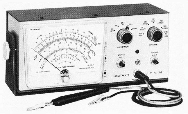
Fig. 7-1 . Heathkit Model IM-28 "Service Bench" VTVM.
The metal case of this instrument is connected to the ground of the internal circuit and to the power-line ground through the green line-cord wire. For proper operation, the ground terminal of the instrument should always be connected to the ground of the equipment under test. There is always inherent danger in testing electrical equipment. Therefore, the user should clearly familiarize himself with the equipment under test before working on it, bearing in mind that high voltages may appear at unexpected points in defective equipment.
When measurements are to be made at high-voltage points, it is good practice to remove the operating power before connecting the test leads.
If this is not possible, be particularly careful to avoid accidental contact with nearby objects which could provide a ground return path. When working on high-voltage circuits, play safe. It is a good practice to keep one hand in your pocket to prevent an accidental shock and be sure to stand on a properly insulated floor or floor covering.
COMBINATION PROBE
The probe, which includes the 2-position switch, should be set to AC-OHMS when the FUNCTION switch is on AC or OHMS, and should be set to DC when the FUNCTION switch is on DC+ or DC-. Both the common lead and the probe include a clip so that the user can make measurements without the necessity of having to hold the probe.
UNDERSTANDING THE VTVM SCALE
At the various RANGE switch positions, the voltage markings correspond to the associated full-scale readings. For DC voltage measurements, the corresponding scale is labeled 0, 1, 2, etc., through 15; and 0, 5, 10, 15, etc., through 50. This same scale is used for measuring ac voltages except for the 1.5-volt and the S-volt ranges. The important features of the VTVM of Fig. 7-1 are shown again in Fig. 7-2 for convenience.
For 1.S volts dc, read the 15-V scale and move the decimal one place to the left. For example, a reading of 8 would be .8 volt. For S volts dc, read the 50-V scale. For example, a reading of 40 would be 4 volts. On the 15-V range, read the 0- to 50-V scale directly. On the 150-V range, read the 0- to 15-V scale and move the decimal one place to the right. For example, a reading of 13 would be 130 volts.
On the 500-V range, read the 50-V scale and move the decimal point one place to the right. For example, a reading of 40 would be 400 volts. When using the 1500-V range, use the 15-V scale and move the decimal two places to the right. For example, a reading of 12 would be 1200 volts.
When measuring up to 1.5 volts ac, read the 1.5-V AC ONLY range directly; this scale is lettered in red. On the 5-V range, use the 5-V AC ONLY scale and read the scale directly. This scale is also lettered in red.
Resistance measurements are read on the top scale which is lettered in green. The marking R X 1 indicates that you should read the scale on the Range switch directly. For R X 100, add two zeros to the reading. For R X 10K, add four zeros and on R X 1 MEG add six zeros or read the scale directly in megohms.
The bottom scale, which is marked with zero at the center, is used for making certain tests or measurements where it is convenient to be able to observe the movement of the pointer either positively or negatively with respect to zero voltage. In using the zero-center feature, the FUNCTI01'\ DC- or DC+ and the ZERO ADJ are turned until the pointer is above the "0" mark on the bottom scale, as is shown in Fig. 7-3.
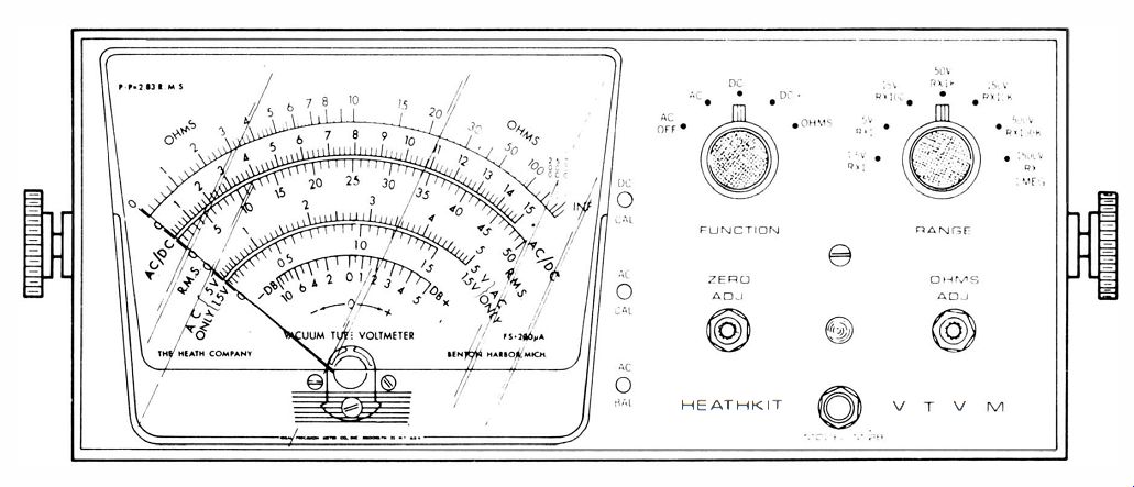
Fig. 7-2. Important features on the front panel of the VTVM shown in Fig.
7-1.
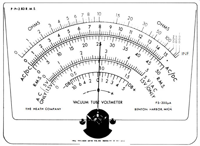
Fig. 7-3. Pointer adjusted to zero center on bottom scale.
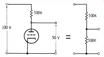
Fig. 7-4. Typical vacuum-tube circuit and equivalent circuit shown to the
right of it.
LOADING EFFECT OF THE VTVM
This VTVM, like most others, has an input impedance of 11 megohms which is considered to be relatively high. The high input impedance is one of the main (if not the major ) advantage of the VTVM as compared to the ordinary VOM.
Using the manufacturers' examples to illustrate this advantage, assume that a resistance-coupled vacuum-tube type of audio amplifier with a 500K plate load resistor is supplied from a plate source of 100 volts, as is shown in Fig. 7-4. Since the voltage on the plate (between cathode and plate ) is shown to be 50 volts, the equivalent resistance of the tube is also 500K. If a 1000-ohms-per-volt VOM is used on the 100-volt range to measure this 50 volts on the plate, the resistance of the meter, which is 100K for that range, is placed in parallel with the 500K of the tube, resulting in an equivalent resistance of 83K. The voltage on the plate of the tube will then drop to 14.3 volts, as is shown in Fig. 7-S. This large error is caused by the shunt resistance, or "loading effect," of the meter. The fact that this low-resistance meter is being used to measure voltage in a high-impedance circuit changes the conditions in the circuit so that the indication on the meter does not accurately represent the circuit voltage when the meter is not connected.
Fig. 7-6 shows the same circuit but shows the 11-megohm resistance of the VTVM as being connected across the 500K tube resistance.
The 11-megohm resistance of the VTVM in parallel with the 500K of the tube has an equivalent resistance of 480K which is relatively close to the original 500K, so the VTVM has relatively little "loading effect" on the circuit. The voltage on the plate of the tube will be reduced by only 1 volt, to 49 volts, as shown.
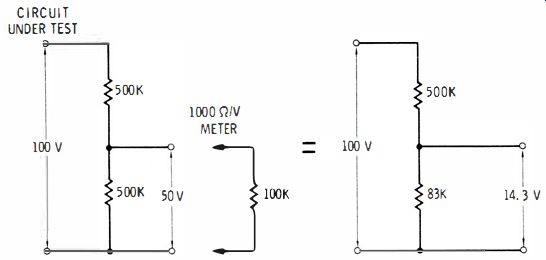
Fig. 7-5. Equivalent circuit of Fig. 7·4 before a 100 n/V VOM is connected
to it (left) and the voltage drop after the VOM is connected (right).
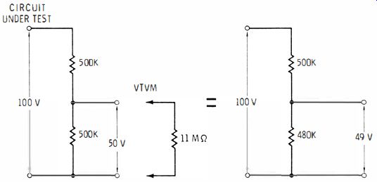
Fig. 7·6. Same conditions as in Fig. 7·5, except using a VTVM to measure the
voltage.
MEASUREMENTS
Measuring DC Voltages
To measure positive dc voltages, connect the common or black test lead to the cold, or common, side of the voltage. In equipment that is operated from the ac line through a power transformer, common is usually the chassis. Set the FUNCTION switch to DC+. Set the RANGE switch sufficiently high so that the voltage to be measured does not exceed the range setting. If the voltage is unknown, set the RANGE switch first to the 1500-volt position.
Touch the test probe ( DC position ) to the voltage point. If the meter does not read in the upper % of the meter scale, reduce the setting of the RANGE switch. A meter reading in the upper portion of the meter scale is usually the most accurate. To measure -dc voltages, turn the FUNCTION switch to the DC- position and repeat the previous steps.
Power-Line Measurements
The manufacturer's directions for measuring ac voltages of the VTVM shown in Fig. 7-1 are adapted for the purposes of this discussion as follows:
WARNING: When your power-line outlet is the 3-wire, polarized type, do not use the common (negative ) lead of this VTVM to measure power-line voltages. To do so may short circuit the power line through the common lead, the chassis, and the green line-cord wire.
1. Set the FUNCTION switch to AC, the range switch to 150 v, and the meter probe to AC.
2. Move the meter common lead out of the way, as it will not be used.
3. Touch the meter probe to one side of the power line. If there is no indication on the meter, you have selected the common side of the ac line; touch the probe to the other side of the line.
4. To obtain contact to a wall outlet, insert a screwdriver blade into one of the outlet openings and touch the probe to the exposed part of the screwdriver blade. Try both outlet openings. Be careful.
5. If you have occasion to measure a 240-volt outlet, such as for an electric range or a dryer, you will get voltage readings with the probe at two of the three openings. Add these readings together to get the actual value of the voltage present.
Measurement of Other AC Voltages
To measure other ac voltages with the VTVM, connect the common (black ) lead to the common, or "cold," side of the voltage to be measured. Set the FUNCTION switch to AC and set the RANGE switch to a range greater than the voltage to be measured, if known. If unknown, set it to 1500 V. With the test probe in the AC position, touch the point in the circuit at which the voltage is to be measured. If the meter moves less than 1/3 of full scale, switch to the next lower range.
The maximum ac voltage that can be safely measured with your VTVM is 1500 volts, and this limit must not be exceeded. The meter scale of the VTVM is calibrated in rms.
The ac voltage readings are obtained by rectifying the ac voltage and applying the resulting dc voltage to the VTVM circuitry. The rectifier circuit is a half-wave doubler, and the dc output is proportional to the peak-to-peak value of the applied ac.
For sine-wave voltages (Fig. 7-7A), the rms value is 0.35 times the peak-to-peak value. For complex waveforms (Fig. 7-7B ) this ratio does not necessarily hold true and may vary from practically zero for thin spikes to 0.5 for square waves (Fig. 7-7C ). For sine-wave voltages over 5 volts, the rms value is read on the same scale as a dc voltage. 'When you are using the 1.5- and 5-volt ranges, the 1.5 and 5-volt ac scales should be read.
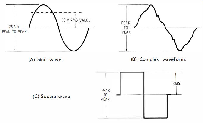
Fig. 7-7. Ac waveforms. (A) Sine wave. (B) Complex waveform. (C) Square wave.
When connecting the VTVM to the circuit under test, the VTVM input resistance R and input capacitance C are effectively placed in parallel with the voltage source. This may change the actual voltage to be measured through loading.
At low frequencies, such as the power-line frequencies of 50 or 60 Hz, the effects of capacitance loading may usually be disregarded; thus, the loading · by the VTVM may be considered the same as connecting a 1-megohm resistor across the voltage source. At higher frequencies, the capacitive reactance decreases. At 10 kHz, for example, it is approximately 170K. Such a value may seriously affect the voltage at the point of measurement.
The loading effect of both input capacitance and resistance depends on the source impedance. In low-impedance circuits, such as 50 to 600 fl, no noticeable error is introduced in the voltage reading through circuit loading. Then the specified frequency response of the VTVM becomes the limiting factor.
As a general rule, it should be kept in mind that frequency response and loading may affect the accuracy of the voltage reading obtained. Consider the resistive loading of 1 megohm regardless of frequency, and the capacitive loading effect at the frequency involved. The actual capacitance of the instrument and leads may also affect the tuning of low-capacitance resonant circuits.
Knowledge of the values in the circuit under test and the values of the input R and C of the VTVM will permit valid readings to be obtained for a wide range of impedances within the full frequency response of the instrument.
Since the VTVM is a sensitive electronic ac voltmeter and since the human body picks up ac when near ac wires, the meter will indicate this pickup. Never touch the probe when the VTVM is set on the lower ac ranges. Zero should be set with the probe shorted to the common clip.
Resistance Measurements
To measure resistance with the VTVM, connect the common (black ) lead to one side of the resistor or circuit to be measured. Set the FUNCTION switch to OHMS and set the RANGE switch to such a range that the reading will fall as near midscale as possible. Set the OHMS AD] control so that the meter indicates exactly full scale (infinity On ohms scale) with the test lead (AC position ) not connected to a resistor or circuit. Then touch the test probe to the other side of the resistor or circuit to be measured. Read the resistance on the OHMS scale and multiply by the proper factor as shown on the RANGE switch settings.
Although a battery is used to measure resistance, the indication is obtained through the electronic meter circuit; therefore, the VTVM must be connected to the ac power line and turned on. Establish the habit of never leaving the instrument set in the OHMS position because this could greatly shorten the life of the ohmmeter battery, particularly if the test leads are accidentally shorted together when lying on the service bench.
Using the VTVM Decibel Scale
Different reference points for 0 dB have been adopted for various purposes. For audio work, the reference for 0 dB is usually standardized as being 1 milliwatt in a 600-ohm load. The voltage across the load can be calculated to be 0.774 volt.
On the 0- to 15-volt scale of the VTVM being discussed, 0 dB will be 7.74 volts. When an ac range lower or higher than the 0- to 15-V range is used, 10 dB should be subtracted from or added to the value indicated for each change in range position. For example, the indication of 0 dB when the RANGE switch is set to 50 V means the level is actually +10 dB; or an indication of 0 dB when the range switch is set to the 5-V range means the level is -10 dB. When the reference level of 1 milliwatt (m W) in 600 ohms is the standard for 0 dB, this level is usually referred to as 0 dBm. The graph shown in Fig. 7-8 makes it convenient to convert ac voltage readings across 600 ohms to decibel readings, assuming that the 0-dB reference is 1 mW. As an example of how to use this graph, if you measure 10 ac rms volts across a resistance or line of 600 ohms, the equivalent value will be 22 dBm; similarly, 2 ac rms volts across 600 ohms will be equal to 8 dBm, etc.
For circuits other than 600 ohms, Table 7-1 may be employed to determine the correction factor. For instance, if we measure 20 ac rms volts, the chart shows this to be equal to about 28 dBm for a 600-ohm circuit; but if the measurement is made across a 150-ohm circuit, the table indicates that we must add 6 dB-the actual value then will be 28 + 6, or 34 dBm.
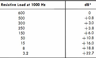
Table 7- 1. Correction Factor, 10 log -------- • dB is the increment to be
added algebraically to the dBm value read from Fig. 7·B.
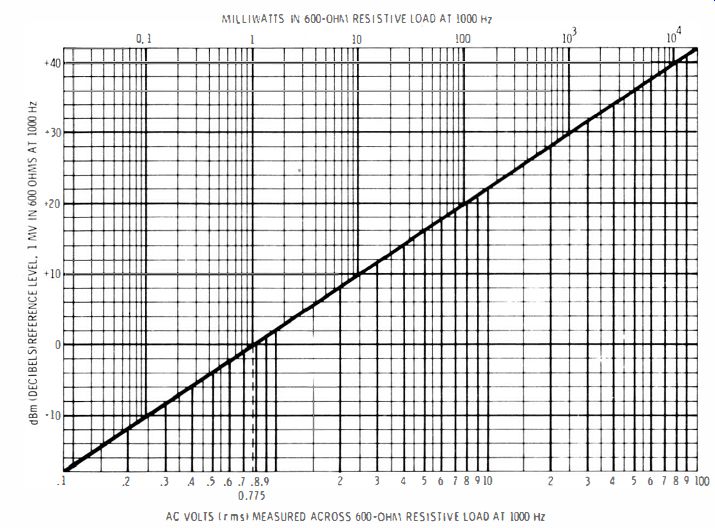
Fig. 7-8. Graph relating dBm to ac rms voltages.
For circuits other than 600 ohms, and not shown in the table, the following formula may be used. In the formula, R represents the resistance of the circuit in which the measurement is made. If R is higher than 600 ohms, the correction factor is negative. For instance, suppose we measure 9 ac rms volts across 6000 ohms . From the graph of Fig. 7-8, it is noted that 9 ac rms volts in a 600-ohm circuit is 21 dBm. The correction factor which must be added (subtracted, in this case, since 6000 is higher than 600 ) is: 600 Correction factor = 10 log 6000 = 10 log 0.1 = 10 x (- ) = -10 dB
Thus, the dBm equivalent of 9 ac rms volts across 6000 ohms is 21 - 10, or 11 dBm.
CARE OF THE VTVM
In general, the suggestions regarding care and maintenance of the VOM or non-electronic analog multimeters, which were covered earlier in this guide, also apply to the VTVM. To review briefly for application to the VTVM, the following precautions should be observed:
1. The VTVM should be properly calibrated before using it.
2. Batteries, when weak, or leaking, should be replaced.
3. Precautions regarding safety should be followed-connect the common lead first, be careful of hot-chassis equipment.
4. Test leads should be kept in repair or not used if defective.
5. A safe storage location should be provided; locations near machinery, dust, dirt, excessive temperatures and humidity should be avoided.
6. Only replacement fuses and overload diodes of the same rating should be used, and replacement parts of the same characteristics and rating should be employed.
7. Repair of the meter movement should not be attempted.
In the next paragraphs, additional items will be considered with regard to the use and care of the VTVM.
CAUSES OF FAILURE OR INTERMITTENT OPERATION
Some causes of troubles in VTVM's are due to negligent or accidental misuse of the instrument. When you first notice something wrong with the VTVM, think back to the last time you used it for that particular function or range. You may possibly remember what you might have done wrong and will then be able to make repairs more quickly.
For example, perhaps you had the function switch set for ohms when you were attempting to measure voltage. Then, noting that there was no expected voltage reading, you double-checked the switch settings, noticed that the function switch was not set to the voltage positions as required, corrected that situation, and then proceeded with the voltage measurement, not realizing that you had burned out a resistor in the ohmmeter circuit. In an accident of this sort, usually it is one of the low-value, ohms-multiplier resistors that is damaged. Typically these have values of 9.45 or 95 ohms, although the values may vary in different instruments.
Many troubles are also due to failure of a component, tube, cable, switch, control, or the wiring. If trouble occurs and you do not know where to start, the best approach is first to determine just which functions of the VTVM do not respond properly. Usually you can isolate the trouble to one or two major circuits. Begin by inspecting those parts and comparing the voltages, resistances, etc., with the normal operating values provided in the manufacturer's instruction manual for the particular instrument being used.
Tube Failure
Occasionally a tube will fail in a VTVM. The result will be noticeable in the operation. The VTVM may fail to respond at all, may not calibrate properly, may respond only on the ac voltage readings, may operate intermittently, or may operate properly only after an unusually long warmup period.
If you are unable to balance the VTVM, or if the balance is unstable, the cause may be the double triode (12A U7, ECC82, etc. ) or the twin diode (6AL5). If there is no reading on any of the ac scales but dc readings are normal, the usual cause is a defective 6AL5. When tubes are replaced, the VTVM should be recalibrated as described in the instrument manual. Before final calibration, the tubes should be aged in the circuit, since their characteristics may change during the first few hours of operation. A tube can be pre-aged if you are anticipating a failure. Pre-aging can be done by applying 100 to 125 volts dc on the plate, connecting the grids and cathode together and to the -dc source, connecting the filament to its rated voltage, and operating the tube in this manner for 40 to 50 hours.
Then place the tube in the VTVM, and recalibrate according to the manufacturer's instructions.
Inaccurate Resistance Readings
If the resistance readings are inaccurate, it may be because the 1.5-volt battery is weak. A way to test the battery will be described later. If the battery does not prove to be weak, one or more resistors in the multiplier circuit may be open or off value-one symptom of a defective resistor is that resistance values measured on the lower ohms ranges will creep in value-the reading will vary as you watch the pointer.
Other Causes of Failure of the VTVM
Other causes of failure of the VTVM include a blown fuse, a faulty on-off switch, an open line cord, a break in the wiring, a poor shield connection on the probe cable, a low dc power-supply voltage, poor socket contacts, a damaged probe resistor, a defective control, or wiring shorted to the metal case.
Battery Test
To ensure accuracy of resistance measurements, the battery should be occasionally tested as follows :
1. Turn the FUNCTION selector to OHMS. Set the RANGE control to R X 1 position.
2. Rotate the OHMS ADJUST control for full-scale deflection of the pointer. Short the probe to the ground clip for about ten seconds.
3. Open the circuit and observe the indication. Any appreciable deviation from full-scale deflection indicates weak cells that should be replaced.
The reason the pointer may fail to deflect full scale is that with the prolonged short circuiting of the probe tip to the ground clip, a fairly high current demand is placed on the battery. This lowers the voltage of a weak battery so that it does not permit immediate full-scale deflection of the pointer when the short is removed.
SPECIAL APPLICATIONS
On many VTVM's, the highest calibrated number on the ohms scale is 1-K. If you are reading ohms and have the range switch on the highest setting (1 megohm), the highest readable resistance is 1000 megohms, which is high enough for most purposes. However, on some rare occasions or for special purposes, it may be necessary to measure a higher resistance. There is a way to do it using an external battery and series resistor, as shown in Fig. 7-9.
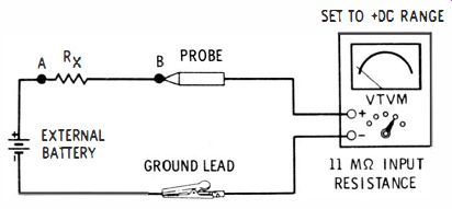
Fig. 7-9. Circuit showing the use of a VTVM to measure resistance beyond 1000
megohms.
The method described by the manufacturer of the RCA WV-98C, which could apply directly or with slight modification to any comparable VTVM, is as follows. The battery symbol may represent an external voltage source of from 20 to 500 dc volts, whatever is required to make a deflection of the pointer. Connect the circuit as shown and then :
1. Set the function selector to +nc volts and measure the voltage at point B (Fig. 7-9 ).
2. Measure the voltage at point A (Fig. 7-9).
3. Compute the unknown resistance, Rx, from the following formula : R ( h) - 11 (volts at A) - (volts at B) x megohms - ( volts at B) Example: The value of an unknown resistance is to be determined with the circuit of Fig. 7-9. An external voltage of 500 volts is applied. The WV -98C measures 2.5 volts at point B and 500 volts at point A. Then, Rx = 11 ( 50 2 ?5 - 2 5 ) = 2200 megohms (approximately ).
Peak-to-Peak Voltage Measurement
The VTVM can be used to measure peak-to-peak voltages by reading directly from the peak-to-peak scales of the VTVM. In most cases, even for complex waves and other nonsinusoidal waves, the readings that are obtained will be accurate. In some cases, where the voltage wave being measured consists of pulses of very short duration, or pulses between which there is a long interval, the peak-to-peak voltage reading obtained will be lower than the actual value which would be more accurately indicated when using an oscilloscope.
High-Frequency Measurement
The VTVM's previously discussed have responses up to 3 to 4 MHz and down to 30 to 40 Hz. For most VTVM's this response is accurate when the measurement is being made across a specific value of resistance such as 100 ohms, 600 ohms, 1000 ohms, etc. For measurement across a circuit of some other resistance, the response may differ.
For example, a certain VTVM that is Bat to 4 MHz when the measurement is made across 100 ohms may be Bat only to 500 kHz when the measurement is made across 1000 ohms. This possible deviation in response for circuits of different resistance should be remembered when making frequency-response checks on audio- and video-amplifier circuits.
For making measurements of voltages having frequencies above the specified response of the VTVM, the crystal-diode probe (available as an accessory for most VTVM's ) should be used. This will extend the response of the VTVM to 250 MHz or more, depending on the VTVM and its associated probe. A crystal-diode probe sometimes is an additional cable and probe that must be used instead of the ac/ohms/dc probe or must be inserted in a different jack. In other cases, the crystal-diode probe is simply placed over the standard probe and used directly.
ERRATIC VTVM READINGS DUE TO STATIC CHARGE
Those VTVM's (and VOM's ) having plastic covers on the meter face may accumulate a charge of electricity when the cover is polished or cleaned. This may cause the pointer to deflect erratically whether the instrument is on or off. The static charges may easily be removed by using one of the commercially available antistatic solutions or a solution of any good liquid detergent and water. Dip a clean, soft cloth in the solution and wipe the surface of the meter cover. The cover need not be removed for this operation.
QUESTIONS
1. How do some VTVM's provide for low-voltage ac ranges?
2. What type of rectifier is commonly used in the power supplies of VTVM's?
3. What is the purpose of the TRANSIT position found on the function switches of some VTVM's?
4. Why does the manufacturer of a VTVM place the calibration controls inside the case?
5. How is the pointer of the meter in a VTVM set to zero?
6. How long should a VTVM be allowed to warm up before use?
7. What precaution should be taken before the ohms function of a VTVM is calibrated?
8. What precaution should be taken when a tube in a VTVM is replaced?
9. What is the purpose of a zero-center scale on a VTVM?
10. What reference is used when decibel measurements are made with a VTVM?
11. Discuss generally what sort of care the VTVM requires.
12. What are some of the causes of failure of VTVM's?
13. What should be done after a tube in a VTVM is replaced?
14. What might be causing the trouble if resistance readings on the VTVM creep in value as you watch the pointer?
15. How can the VTVM be used for measurement of resistances considerably higher than the highest range for which it was designed?
16. If readings obtained on the VTVM are erratic, what might be the cause?