SPECIAL FEATURES OF SOLID-STATE INSTRUMENTS
The solid-state analog volt-ohm-milliammeter is sometimes referred to as a transistorized VTVM. Solid-state analog instruments perform much like the VTVM; they offer most of the advantages of both the VOM and the VTVM. They are lightweight, compact, battery operated, portable, versatile, and they require no warmup time. The active components in solid-state instruments are either conventional bipolar transistors, field-effect transistors (FETs), or a combination of both. Solid-state analog instruments are variously referred to as transistor voltmeters (tvm's); transistor volt-ohm-milliammeter (t VOM's ), electronic multimeters (emm's ), field-effect transistor VOM's (FET-VOM's ), solid-state VOM's (ss VOM's ), and so on. In most cases we will refer to all of these as (transistor volt-ohm-milliammeter) . Most t VOM's have an 11-megohm input impedance, the same as the typical VTVM; however, some have a higher input impedance, such as 15 megohms or 21 megohms. As compared to the VTVM, the typical tVOM can measure lower dc voltages, is more stable, offers greater portability, can provide "low-power" resistance measurement, and seldom needs to be reset to electrical zero. The t VOM has replaced the VTVM to a great extent for many uses. Also, except where low cost is important, the t VOM is slowly replacing the conventional VOM.
CIRCUITS OF TYPICAL INSTRUMENTS
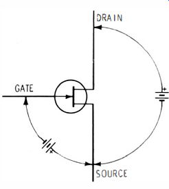
Fig. 8-1 . Voltages applied to an FET.
Some typical t VOM's will be examined in this part of the guide.
Since most tVOM's utilize FETs, let's stop to examine briefly how the FET operates.
The operating principle of the FET, schematically shown in Fig. 8-1, is as follows. A negative voltage, which is similar in action to the bias of a vacuum tube, is applied between the gate and the source of the FET. Also, a positive voltage, similar to the plate voltage of a vacuum tube, is applied between the drain and the source, establishing a current between source and drain. When the gate is biased negatively enough, "pinch-off" (like "cutoff" in a tube ) occurs, stopping the drain current. With typical operating voltages applied to the gate, source, and drain, a more-negative gate bias results in less drain current, and a less-negative gate bias results in more drain current. The negative voltage between gate and source results in negligible gate current; thus, the gate-to-source impedance is high. The input signal is normally connected between the gate and the source. It is its high input impedance that makes the FET popular in solid-state measuring instruments.
A simplified solid-state metering circuit is shown in Fig. 8-2. Transistor Q1 is an FET which provides a high-impedance input for the dc voltage to be measured. Transistors Q2 and Q3 are part of the amplifier that drives the meter, M1.
For the measurement of ac voltages, the same basic circuit may be employed, but with the addition of a rectifier circuit as for the VOM and VTVM. For lowest-range ac measurement, sometimes an additional amplifier stage is added.
A solid-state metering circuit also can be based on the arrangement of Fig. 8-2. In most respects it is similar to the ohmmeter circuits of the VOM and VTVM.
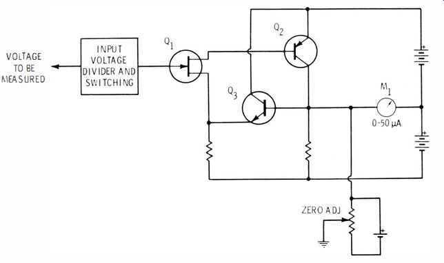
Fig. 8-2. Simplified solid-state metering circuit .
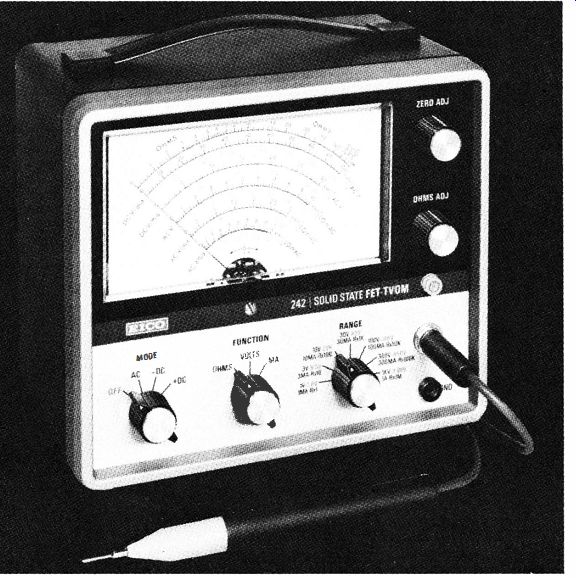
Fig. 8-3 shows an example of a FET-t VOM, the EICO Model 242.
It provides for measurement of dc voltages between 0.01 and 1000 volts and up to 30,000 volts with the addition of a high-voltage probe. Voltage ranges for ac cover from 1 volt rms full scale to 1000 volts rms full scale and from 25 Hz to 2 MHz or up to 250 MHz with the use of an rf probe. A low-voltage source permits measurement of resistance in transistor circuits without introducing error due to transistor conduction, and it lessens the chance of damage to the transistors being tested. Choice of operation either from self-contained batteries or ac power is provided.
The input circuit of the instruments includes a FET and a differential amplifier circuit, as shown in simplified form in Fig. 8-4. The FET, connected as a source-follower stage (Q1), drives a differential amplifier consisting of silicon transistors Q2 and Q3. Whether the parameter being measured is current, resistance, or voltage, the meter reading on MI is a function of the dc voltage applied to the Q1 FET. When the emitter currents through Q2 and Q3 develop identical voltages across their respective emitter resistors, R18 and R19, the two emitter voltages will be identical. No current will flow through the meter at this time. Note that the base current of Q3 is held constant by voltage-divider elements R20 and R21, thus maintaining the emitter current and the voltage developed across RI9 at a fixed value.
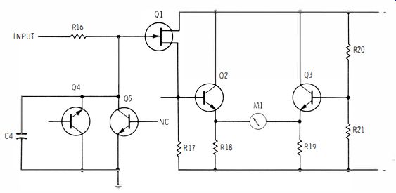
Fig. 8-4. Basic FET-t VOM circuit for the EICO Model 242.
The operation of Q2 is controlled by a voltage divider consisting of FET QI (acting as a voltage-variable resistor) and R17. When a dc voltage is applied to the gate of source follower Q1, its source voltage, direct coupled to the base of Q2, changes accordingly. Since Q2 is connected as an emitter follower, its emitter voltage follows the change. This unbalances the voltages between the emitters of Q2 and Q3 and deflects the meter pointer. In this manner, meter deflection is made a function of the dc voltage applied to the gate of Q1.
Transistors Q4 and Q5 are used in conjunction with resistor R16 to protect FET Q1 from accidental overloads. With the bases of Q4 and Q5 disconnected, they act as high-quality temperature-compensated zener diodes. This parallel transistor circuit presents an infinite impedance to input voltages up to approximately 10 volts, but it becomes a short circuit to higher voltages. Excess voltages are dropped across R16.
The voltage-measuring circuit of the FET - tVOM is generally similar to that of the typical VTVM, so we will not go into voltage-measuring circuits here. Many FET-t VOM's and other solid-state instruments provide for measurement of direct current and sometimes alternating current; the instrument being considered here provides for measurement of both ac and dc current. An analysis of these circuits is worthwhile at this time.
Input Circuit for Measurement of DC Milliamperes
Direct-current measurements ranging from 0.01 milliampere (10 microamperes ) to 1 ampere can be made with the Model 242. These measurements are made by passing the current through a resistance of known value, then measuring the voltage drop across the resistance.
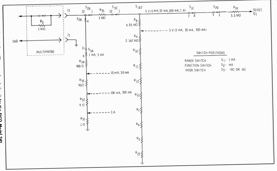
Fig. 8-5 DC milliamp
Fig. 8-5 shows the input circuit arranged to measure up to 1 milliampere of current. When the test probe and common lead are connected in series with the circuit to be tested, the external current Rows through resistors R31 through R34. Assuming that 1 milliampere of current flows, a voltage drop of 1 volt (1 milliampere X 1000 ohms ) is produced. The 1-volt dc level is then applied through R35 and voltage-divider elements R8 through R13, R7, R6, R5, and R22. This 11-megohm network is identical to that used for measuring dc voltage, except that R35 replaces probe resistor R1. With ?? volt fed through R13 to FET Q1, full-scale deflection is produced on the 1-mA dc scale.
When RANGE switch S1 is set to the 3-mA position, current flows through the same network (R31 through R34). Assuming that 3 mA of current flows in the external circuit, 3 volts dc is developed across this network. The 3-V tap on the voltage divider is automatically selected at this time.
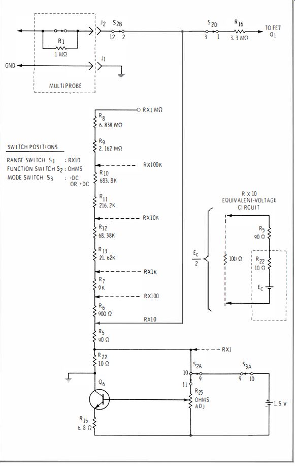
Fig. 8-6. Ohms input circuit of the EICO 242.
When measuring 10 mA or 30 mA, the external current flows through R31, R32, and R33, again producing 1 volt or 3 volts, respectively. Again, the same two taps are used on the voltage divider to produce the voltage for proper deflection.
Operation is similar on the remaining dc current scales. In each case, either 1 volt or 3 volts is developed and either of the same two voltage-divider taps is selected.
Circuit for Measurement of AC Milliamperes
The ac milliampere circuit functions similarly to its dc counterpart. The same resistors (R31 through R34 ) are used to develop either 1 volt or 3 volts ac. In this case, the ac voltage is coupled through a blocking capacitor to a voltage-doubler circuit where it is rectified to dc. The dc voltage is then applied to divider resistors as before, and the proper voltage is tapped off at either the I-V or the 3-V tap for proper deflection on the range in use.
FET -tVOM Ohmmeter Circuit
As shown in Fig. 8-6, the ohmmeter circuit of the EICO Model 242 uses a constant-current source consisting of transistor Q6, OHMS ADJ control R25, resistor R15, and the 1.5-volt battery; all of these acting together maintain the current through collector load resistor R22 at a constant value. The bias for the base of Q6 is set by means of the OHMS ADJ control so that, with no external resistance connected, 0.91 volt is applied to the FET Q1 gate, producing full-scale deflection, designated as infinity (00) on the meter face. However, with the ohmmeter in the R x 10 position, as shown, if an external 100-ohm resistor is connected between the probe and the common test lead, the voltage at the gate of Q1 is reduced to one-half its original value. This is shown in the equivalent voltage circuit of Fig. 8-6.
Therefore, measurement of 100 ohms on the R x 10 scale causes the meter to point to the halfway mark, or 10, on the OHMS scale. If the external resistance is lower in value, less voltage is fed to the gate and a lower ohms reading is obtained.
The resistance connected in series with the constant-voltage source increases by a factor of 10 as the RANGE switch is rotated through each position, from R X I to R X I M. Resistance measurement above 1000 megohms can be made by employing an external battery or voltage source between 20 and 500 volts, using the same procedure as described earlier for extending the resistance-measuring range of the VTVM.
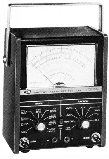
Fig. 8-7. B & K Precision Model 277 solid-state electronic multimeter.
Courtesy of B & K Precision Division of Dynascan Corp.
The B&K Model 277 Sol id-State Electronic Multimeter Another solid-state electronic multimeter employing a FET input circuit is the B & K Model 277, shown in Fig. 8-7. One of the special features of this instrument is that it provides for measurement of dc current down to O.I-microampere full scale. Also included are high and low-power ohms ranges for critical testing of semiconductor circuits.
The B & K Model 277 also includes conventional high-power resistance-measuring ranges since these are necessary when trying to determine if the transistor in the same circuit is good or bad. With the high-power resistance-measuring circuit in use and the test leads connected first one way across the transistor terminals, then reversed, the two readings are compared to obtain the front-to-back ratio. This ratio provides a good indication of the condition of the transistor.
The RCA WV-500B Solid-State Volt Ohmyst
The solid-state RCA WV-500B Volt Ohmyst, shown in Fig. 8-8, does not utilize FETs, but rather employs a four bipolar-transistor amplifier circuit designed especially for good linearity and stability.
The manufacturer's description of the circuit (shown in Fig. 8-9 ) is based on the following descriptions.
Metering Circuit--The input voltage (from the ac/ dc voltage divider or ohms divider ) is applied across the bases of Q3 and Q4, positive to Q3 base negative to Q4 base. These transistors provide a nearly infinite impedance. This high impedance is achieved through a controlled positive feedback network, R13A, B, R32A, B, and the two impedance-adjust potentiometers, R45 and R46. Transistors Q3 and Q4 serve as preamplifiers driving the bases of Q1 and Q2. In effect, transistors Q3 and Q1 amplify the positive portion of the signal, and Q4 and Q2 amplify the negative portion of the signal.
Negative feedback through R28 and R29 results in high impedance at the Q1 and Q2 bases to prevent loading the Q3 and Q4 emitters. The outputs of Q1 and Q2 drive the 50-microampere meter.
Potentiometer R30 is used to balance the Q3/Q4 input. This is a factory adjustment and need not be readjusted unless the transistors are replaced. The front-panel ZERO control, R21, balances the amplifier output with no input signal applied.
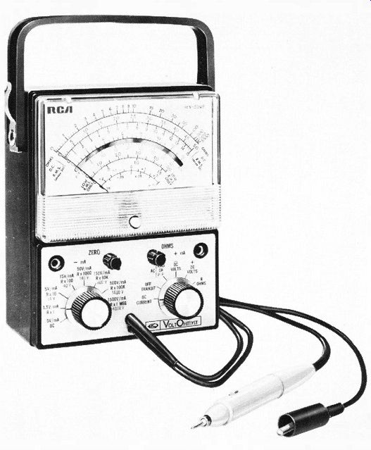
Fig. 8-8. RCA Model WV·500B solid-state Volt Ohmyst.
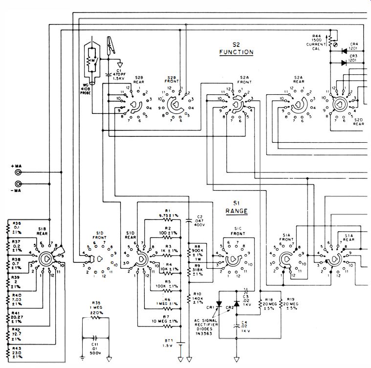
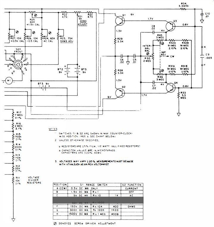
Fig. 8-9. WV·500B schematic diagram. Courtesy RCA 119
Resistors R33 and R34 serve to isolate and protect the amplifier circuit. Capacitors C5 through CIO are bypass capacitors to prevent ac signals from affecting the metering circuit.
The accuracy of the WV-500B is maintained throughout the usable life of the batteries. Since current drain of the instrument is very low, battery life is approximately equivalent to shelf life; there is no provision for powering the instrument from the ac line.
Silicon diodes CR3 and CR4 are connected across the meter terminals to prevent meter damage due to accidental overload.
DC Voltage Circuit--The dc voltage input is applied through the isolation resistor in the probe to the voltage-divider network (range ), resistors R11 through R17. The voltage from the divider network is then connected to the transistorized metering circuit.
DC Current Circuit--The transistor amplifier is not used in the dc current function. A separate shunt resistor (R36 through R43 ) is connected across the meter for each of the current ranges. The cur
rent input is connected directly to the meter and shunt circuit. Potentiometer R44 is used to calibrate the current-measuring function.
AC Voltage Circuit--When the Volt Ohmyst is used to measure ac voltage, the signal is first rectified by diodes CRI and CR2 which form a full-wave peak-to-peak rectifier. The circuit components are chosen to provide a long time constant. When the signal swings negative, C3 is charged through CRI to the negative peak value of the voltage. As the input signal starts in a positive direction, C4 charges to a value equal to the sum of the positive and negative peaks. Because of the relative time constant, the voltage across C4 will be maintained at the peak-to-peak value of the ac signal. This signal, now, dc is fed through the voltage-divider network and then to the metering circuit.
Resistance Circuit--The voltage from battery BT1, 1.5 volts, is applied through the selected ohms divider resistor (R1 through R7 ) to the external resistance under test. A voltage divider is formed by the range resistor and the external resistance. The output of this divider is fed to the metering circuit.
Simpson Model 31 3-2 Solid-State VOM
The Simpson Model 313-2 solid-state VOM is shown in Fig. 8-10. It includes a larger, 7 1/3-inch meter, a mechanical "on" indicator to show when the instrument is powered without contributing to battery drain, a BAtt TEST position on the function-selector switch to show the condition of the 9-volt battery, an input resistance of 11 megohms, an overload protection, a multifunction test probe (not shown ), and a shielded cable which plugs into the type BNC connector at the lower center of the instrument.
Triplet Model 603 VOM
The Triplett Model 603 VOM is shown in Fig. 8-11. According to the manufacturer, this instrument can be left on for as long as One year or more and still operate satisfactorily from the same 9-volt battery. This model includes a low-power ohms circuit and an automatic-polarity circuit which allows the user to make dc measurements without having to worry about polarity, thus saving time in many cases where a number of measurements are to be made. For conventional polarity measurements, either the + or the - push button at the lower-left side of the front panel is depressed. For automatic polarity, both of these are depressed at the same time.
Two types of batteries are used in this instrument, a D cell for resistance measurements and two 9-volt batteries for the amplifier circuit. When the range switch is in the BAtt CHECK position, the condition of one of the 9-volt batteries may be observed on the meter dial when the + push button is depressed; the condition of the other 9-volt battery is observed when the - push button is depressed. If the pointer falls within the BAtt OK range shown below the upper end of the scale, the battery being tested at that time is in satisfactory condition. The best test for the condition of the D cell is to see whether the pointer can be brought to zero ohms with the instrument in any of the resistance-measuring positions. If the pointer cannot be brought to zero by adjustment of the OHMS ADJ control, the D cell should be replaced. An additional check of the D cell is recommended by occasionally measuring a resistor of known value between 5 and 10 ohms on the X 1 range. If the resistance reading is low, the D cell should be replaced because the low reading indicates that the internal resistance of the battery is too high causing the low reading.
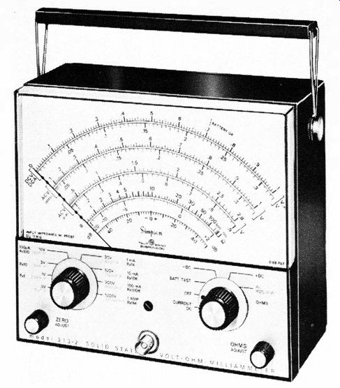
Fig. 8-10. Simpson Model 31 3·2 solid-state VOM. Courtesy Simpson Electric
Company
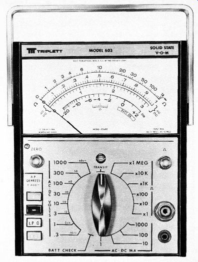
Fig. 8-11. Triplett Model 603 solid-state VOM.
Sencore FE27 Field-Effect Multimeter One manufacturer provides a series of multimeters that utilize a number of push-button switches rather than one or more rotary switches. An example is the Sencore Big Henry FE27 Field-Effect Multimeter, shown in Fig. 8-12. The FE27 has a 15-megohm input resistance and has been designed to withstand unusual degrees of both mechanical shock and electrical overload. Accuracy is 1.5% on dc voltages, 3.0% on ac voltages, and 2% of arc on ohms measurements. The lowest dc voltage range is 0.3-volt full scale.
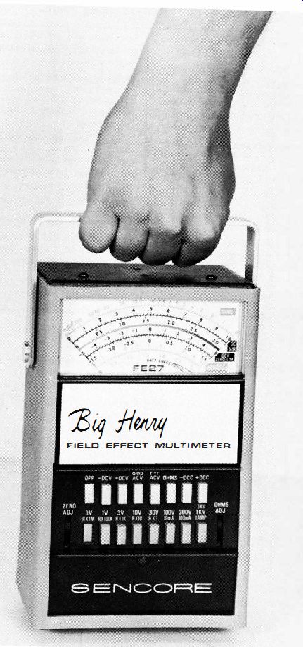
Fig. 8-12. Sencore Model FE27 field-effect multimeter.
CARE OF SOLID-STATE INSTRUMENTS
Solid-state instruments require the same careful handling as the VOM and VTVM, since they contain the same type of meter movement. Also, they are affected by high extremes of temperature and humidity.
Batteries in solid-state instruments can be expected to last six months to one year or more. When the instrument is not in use, it usually should be turned off to extend battery life. Batteries may have their useful life shortened somewhat if they are operated in abnormally warm surroundings. If operated in cool or cold surroundings, batteries will last longer. But at about 0 deg. F and below, battery capacity will decrease; below about -200F dry-cell batteries will provide no output.
When batteries are replaced, care should be used to be sure that proper polarity is observed. In some instruments, that batteries are soldered into the circuit to ensure proper and continuous contact.
When soldering leads to batteries, first "tin" the battery terminals; that is, apply a small coating of solder to the positive and negative terminals. Then it will be easier to solder the leads to the terminals. Instruction manuals for various solid-state instruments contain further directions for determining when batteries should be replaced and how they should be installed or connected.
Check the manufacturer's manual for directions on removing the instrument from the case, for changing fuses, for calibrating and adjusting, and for setting the pointer mechanical zero adjustment.
When the t VOM is not in use, set the function-selector switch to the off position (if there is one ) to conserve battery life and also to shunt the meter to prevent it from moving excessively while in transit.
Instruction manuals also include troubleshooting hints for determining whether the batteries or other components are at fault when problems arise. Typical of such troubleshooting hints is the information in Table 8-1, which is provided by RCA for users of their Master Volt Ohmyst Model WV-510A.
------------------

Table 8-1. Troubleshooting Hints
Instrument fails to operate on all functions.
9-volt batteries dead. Probe defective.
Check continuity.
Voltage readings low an battery operation, especially at right-hand side of meter scale.
9-volt batteries require replacement.
Meter cannot be adjusted full-scale on ohms function.
1.5-volt battery weak.
Instrument cannot be zeroed on any voltage function.
Check transistor amplifier circuit.
Meter pointer bangs hard left or right, depending on function switch setting.
Open or short circuit in amplifier metering circuit.
Meter pointer sticks, or is sluggish on all functions.
Meter movement defective.
Instrument fails to indicate properly on any ac voltage range; operates normally on dc volts and ohms.
Diodes CR3 or CR4 defective. C1, C10, C11, R3S to R37 defective.
Instrument inaccurate on 500- and 1500 volt ac ranges.
Resistors R3S, R36, or R37 defective.
Instrument inaccurate on any ac or DC voltage range. Ohms all right.
Check voltage divider resistors R40 through R46.
Resistance readings inaccurate.
Check resistors R28 through R34. Poor connection to 1.5-volt battery. High internal resistance in battery.
Instrument inaccurate or inoperative on current ranges only.
Check resistors R 19 through R26.
--------------------
QUESTIONS
1. Name some of the advantages of solid-state voltmeters and VOM's.
2. What is a FET?
3. What feature of the FET makes it popular for use in instruments used for measuring?
4. Describe the purpose of the gate, source, and drain in the FET.
5. Sketch a schematic of a simple solid-state metering circuit.
6. If the function switch includes a BATT position, what is the purpose of this position?
7. What is the input impedance of a typical solid-state VOM?
8. What general function does the FET serve in an electronic VOM?
9. How long do batteries generally last in solid-state instruments?
10. What is the lowest temperature at which battery-powered instruments can generally be used?