THERE are many kinds of measurements for which the VOM is either directly usable or for which some simple addition can be made external to the meter. But an instrument which does not have sufficient internal resistance or sensitivity can possibly load the source (such as the plate or screen of a tube) so that measurements (such as voltage) might well be false readings. Now sup pose you have nothing but an insensitive instrument. This could be a VOM with a 1-ma meter having only 1,000 ohms per volt. How can you still make accurate measurements?" This is not nearly so difficult as it sounds, if you have a VOM with several ranges.
Measuring with an "insensitive" meter
Suppose you have a source (Fig. 701-a) which has an internal resistance of Ri and a voltage V, and let us also suppose you want to measure the emf across a resistance R. in parallel with this source.
But your meter drops the voltage somewhat, as a result of its loading action. Say the voltage drops, on one range, to V'. For this range, select the voltage scale on your VOM which gives a usable reading, but with the possibility that it could also be read on the next lower range. For example, if the voltage were 8, and you have both 10- and 30-volt ranges on your meter, the 30-volt range is the one you'd read V' on. Now read the voltage on the next lower range, and call this V". This will not be the same portion of V', because we are now going under the assumption that the meter loads the circuit. Thus it would load the circuit more on the lower range. The voltage would read even more below the actual value than on the higher range.
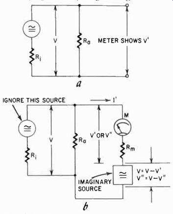
Fig. 701. The VOM may not indicate the correct amount of voltage because it
may load the circuit being checked.
The voltage difference, V- V' (which we can call v) can be regarded as a voltage in series with the meter. It is used to drive the current through the internal resistance (R1) of the source and the parallel resistor R. (Fig. 701-b). Ignoring the voltage V, we will simply look at the source as if it were nothing but an internal resistance. This sounds odd, but we'll come to a solution of the problem soon. The meter indicates the voltage V', and the current through it is:
V I'
' Rm
in which R, is the meter's internal resistance. Now our imagined source must drive this current through R, and R. in parallel. The resistance of the parallel resistances is:
R, x R.
= R.
Ri R.
and the voltage v = I' X Re.
If we do the same thing on the next range down, the voltage V- V", will represent a second reading we can call v". This again we can consider as before and the value of v" = I" (the current through the meter now) X R.
These two voltage differences, v and v" are related just as their proportion V'/R.1 and V"/Rm2 (in which the values R.1 and Rm2 are the meter resistances on the two ranges) because:
V' xp, I' =-and I" = R. R.
If we now divide the values v and v":
- V" v"
- V' then we find that the resistances R1 cancel and the result is:
V" Rini V" V' X Rm2 V
Of course, the ratio Rm1/Rm2 is exactly the ratio of the meter ranges, and this ratio we call Q. We can now rewrite the equation above as:
- V" V" r,
-" - V' V'
If we solve this simple equation for V, we find that V- (Q-1) Q- V'/V" This still looks pretty complicated, but note that we now have a relationship expressed strictly in values we know. We have eliminated all such terms as internal meter resistance, internal resistance of the source, current through the meter, and even the difference voltage. We can measure V" and V' and we know Q. Thus by measuring the sagging voltage source on two ranges of the meter we can come to an accurate measurement of the voltage of the source, regardless of the load on the vom.
For example: suppose you have a meter with a 12- and a 30-volt scale. This amounts to a Q of 2.5 (the quotient of the ranges).
If we connect the meter to a source, and on the 30-volt scale measure a value of 12 volts, and then turn the meter to the 12-volt scale and measure 8 volts there, then:
(2.5- 1) 12 1.5 X 12 V- =18, 2.5- 12/8 2.5- 1.5 and our actual voltage would be 18. Note that we need know nothing about the meter, nor about the source. We need know only the ratio Q of the two ranges, and read the voltage on both.
Fig. 702 is a nomogram designed to accommodate most standard meter-range ratios. Example 1, the dotted line, shows the problem we worked out. Let's try another one.
Suppose on a 300-volt scale, we read 90 volts and on the 150-volt scale, 60. Now Q = 2. We locate in the nomogram the set of scales labeled Q = 2. On one of these (also labeled V'), we find the point 9 (if a scale does not read far enough, multiply all scales with the same number-in this case 10) and on the Q = 2 scale labeled V" (at the bottom) we find point V" = 60. By connecting the two points with a line and extending it to intersect the vertical line (dotted line called "example 2"), we find that the actual voltage is 180.
The nomogram is equipped for scale ratios of 2, 2.5, 4 and 5, since we seldom encounter greater or other ratios in meters.
For those who are mathematically inclined we include simply the fact that the scales are on lines at the right angles, and that the V' scale always bisects the right angle between the V and the V" scales.
If you are not interested in making your own scales, simply use the formula if you run across odd scale ratios as you might, for example, in home-built instruments.
Here, then, is a method to read accurately with an insensitive meter a voltage which should be read with a more sensitive meter having higher resistance. But note that it can also be applied as a correction on readings made with a high-resistance (20,000-ohms-per-volt) voltmeter. For example: suppose on the 300-volt range of such a meter we read 82 volts, and on the 150-volt scale, 78. Then, if we have no reason to suspect inaccuracy in the instrument, we find the line shown as "example 3" in the nomogram, and read the actual voltage as 86.
Of course, with an instrument which has an accuracy of 3% full scale, this is cutting matters pretty fine, and you may well be mis taking inaccuracy for loading. But if this is not a consistent error in different situations, preferably including one where you know loading makes little difference, you can accept this correction. If your voltage source is a very low impedance one, such as a battery, you can accept it more easily.
The correction we have shown here works equally well for ac and dc, and in fact for ac at any frequency for which the meter response remains accurate, so long as we can assume that there is no phase shift in the current or voltage. If the phase shift in one range is different than in the other, as it would be if we measured with an inductive or capacitive circuit (in place of R), then our correction is no longer accurate. It is, of course, possible to set up a special nomogram for these instances, but only if you were to deal with the same kind of measurement every day would such a thing be profitable. And in that situation you could probably afford a more sensitive meter to do the job without correction.
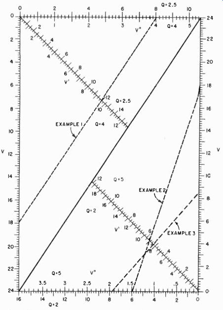
Fig. 702. Nomogram to compensate for loading by the VOM, with out requiring
data on meter resistance, etc. For higher figures than the scales, simply multiply
all scales by the same number, whether this be 2, 3, 5, 10, etc.--whatever
is needed to reach the appropriate voltage readings.
Testing batteries
In the radio and automotive fields, testing batteries is one of the most often used and most needed tests. You may have seen special battery testers in a garage or shop, but you can do the same thing with a VOM if you are willing to make a number of simple accessories. Although a battery tester is not exactly a VOM or can't even be considered a multimeter, it may help you to understand how such a tester is made and functions.
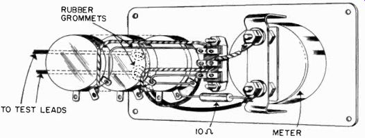
Fig. 703. Pictorial diagram of a battery tester. This exploded view shows
the relationship of the components to each other, and the required wiring.
A pair of color-coded test prods (red and black) are connected to the two wires
marked "to test leads." (Heath Co.)
Fig. 703 is a pictorial of a battery tester. The circuit diagram is shown in Fig 704. Designed especially for testing A- and B-batteries, it is not designed or intended for checking auto batteries.
The meter, a 15-ma instrument, is put in series with a 10,000-ohm potentiometer for testing B-batteries. This allows testing with up to 15 ma, sufficient to tell whether a B-battery is going to sag under the load. In practice a B-battery is seldom called upon to deliver much more than this amount.
For testing different-voltage B-batteries we would, of course, prefer to change the load resistor, and for this reason a potentiometer is used. On the front of the meter there is a scale, and the series resistance is adjusted in accordance with the B-battery voltage marked on this scale. The entire 10,000 ohms would be used for batteries of 180 volts and up, but not many batteries over 150 volts are used. It is possible to overload the tester with a 300-volt battery capable of delivering 15 ma or more, but as always, there has to be a limit on the instrument somewhere, dictated by practical economics.
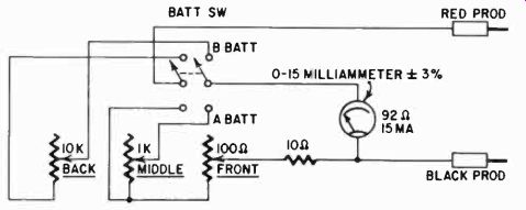
Fig. 704. Schematic diagram of the battery tester shown in the previous illustration.
(Heath Co.)
The A-battery section is similar, except that here the meter is in series with a 1,000-ohm potentiometer and this combination is shunted by a 100-ohm pot and 10 ohms in series. This means that the lowest shunt for the meter is 10 ohms and, since the basic meter has a resistance of 92 ohms, the meter is capable of reading 150 ma. For example, a 1.5-volt battery would be tested with about 150-ma load, normal for that voltage. Higher-voltage batteries would of course get a similar load, since the series resistor is set higher as well as the shunt. Thus, with a voltage setting of 8 volts, the series resistor would he 500 ohms and the shunt about 50 ohms, more or less. The current drawn is about 8/500 = .016 amperes, or 16 ma. The shunt allows the meter to read approximately 35 ma so that a good battery will show about halfway deflection on the meter, and a very good battery a little more. These figures are only approximate and illustrative.
Using the VOM to check storage batteries
Fo make your own accessories to test batteries, all you need is your VOM and a means of loading the battery. Let's start with a problem child first.
An auto battery should be capable of delivering about 50 amperes continuously for several minutes without showing much drop in voltage. For this, on a 2-volt cell, you would need a resistance of about 0.04 ohm. This is easy to make, for 21/2 feet of No. 10 copper wire-if it is bare-has exactly 0.04 ohm of resistance and can carry almost indefinitely a current of 50 amperes. All you need then is to coil this wire (to save space) and provide some means of connecting it to the battery.
Fig. 705 shows how you can make this connection easily. Two small file handles each have a piece of 20-penny nail inserted in them, with the point sticking out. The No. 10 wire is soldered to the nails; test leads from the VOM are clamped onto the ends of the No. 10 wire left sticking out, and there you have a first-class tester for 6- and 12-volt auto batteries, to be tested cell by cell.
The meter is set to read the voltage of each cell. Whenever the tester is applied to the battery, it should be held there for at least 15 seconds. If in that time the battery voltage drops more than 20%, the battery should be charged or replaced if it has just been charged. The 20-penny nails must be pushed into the terminals with considerable force to make adequate contact with the lead battery terminals.
Other battery testers are simple to understand. You will not need to make shunts for your meter since it is more than likely that it has adequate current ranges. If it does not, Section 6 tells how to make additional shunts. Series resistors must be calculated so that the appropriate current will flow. Here is a cue: the current for a 1.5-volt A-battery must be about 150 ma, and so on up to about 15 ma for the 15-volt unit. To make a more severe test, simply put on a heavier load to increase the current.
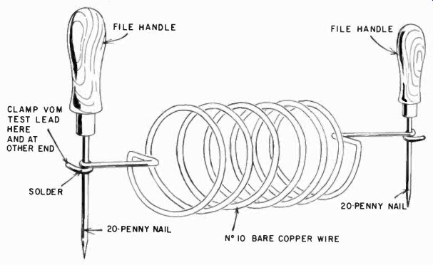
Fig. 705. This is a simple home-made accessory that permits the use of the
VOM as an auto battery tester. This unit puts a direct short circuit across
the battery. Allow about 15 seconds for the test, but not longer. A heavier
wire than No. 10 is a move in the right direction, but do not use a lighter
gauge since it will become quite hot and may burn out.
Checking B batteries
The manufacturer usually specifies the normal full-load current of a battery. For B-batteries this is a great deal less than for heater supplies. If you have, say, a 90-volt battery in a portable receiver, the best way to test is with the receiver on. If the battery shows less than 70% voltage under full load (in this case, 63 volts), it needs replacement. (Portables are so designed that they will operate satisfactorily with 70% to 80% of the battery voltage.)
Checking hearing-aid batteries
Similarly, hearing-aid batteries should be tested in the hearing aid with the instrument turned on. Most radio-supply house catalogs will show not only the current and voltage but also the milli ampere/hour rating.
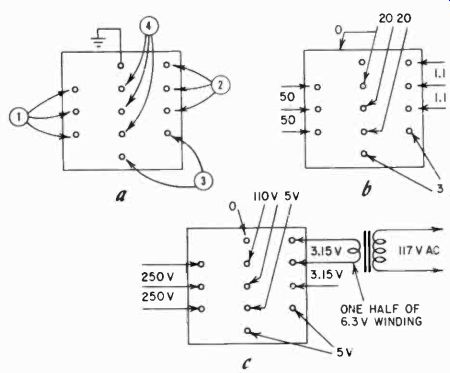
Fig. 706. An unknown transformer can be identified with the help of the VOM.
Using the resistance scales of the VOM, group the transformer terminals (a)
by making a continuity check. If the resistance is high enough, you will be
able to locate the center tap. Next, check the resistance of each winding (b)
which may identify center taps and approximate voltage class. Finally (c) apply
a low voltage across one winding and measure the voltage across the others
which will identify the winding. Note that the primary here is tapped for two
voltages, as it often is on military equipment.
Checking transformers
Transformers are available in many shapes and sizes, new as well as surplus, and they are one radio component not too readily identified as to values and connections. Quite often the leads of the transformer will get painted or covered with black wax, so the color coding becomes indistinct, or the terminals on potted transformers will be marked with pretty numbers which give absolutely no clue as to the voltage, connections, etc. But, fortunately, if you .have a VOM and a low-voltage ac supply, such as from a filament transformer, you can soon work out the problem.
Checking power transformers
Assuming that we are going to work on a power transformer, the first step is to make a continuity check of the wires or terminals.
You can then group them as shown in Fig. 706-a. If you are dealing with wire leads, it is a good idea either to tag the wires or to twist those which belong together, so you can recognize the pairs' or groups.
Next, check the dc resistance between the wires that show continuity. You are not specifically interested in making a precise measurement of the windings, just in their relative resistance, be cause by this means you can identify the approximate voltage range of the windings. You will want to know particularly if there is no measurable resistance between terminals, For then they might be common to the same winding end.
While checking the resistance on the windings, you may be able to determine which of the three connections on a winding is the center tap. The resistance between it and either one of the others is always less than that between the other two (Fig. 706-b).
Finding turns ratios and voltage ratings
Finally, to identity the turns ratios, and perhaps the voltage ratings of the windings, apply a small ac voltage to the winding which measures low in resistance, and then measure the ac voltage developed across the other windings. For example, let us say you put a voltage of 3.15 across one of the windings. Then the winding which produces a 55-volts ac is likely to be a 110-volt winding, etc. If this winding turns out to develop 69.3 volts, it may still be the 110-volt winding: you have simply put the 3.15 volts across a 5-volt winding instead of a 6.3-volt one.
In this way, as shown in Fig. 706-c, you can gradually work out the voltage ratings for all windings, for in radio work these are al most certainly standard. You may deal with 2.5-, 5-, 6.3- and 7.5-volt filament windings, but of these only the 5 and 6.3 are now common.
400-cycle transformers
If you find that tie transformer does not check out on the standard voltages at all, yet you have reason to believe that it is nevertheless a power transformer, then you may be dealing with a surplus 400-cycle type. These will show unusually low voltages on 60 cycles. If you were to try to use a 110-volt, 400-cycle winding on a 110-volt, 60-cycle current, the winding would almost certainly burn out since its impedance would be too low.
A transformer must always have at least four terminals, unless it is an autotransformer, used for stepping voltages up or down without isolating them from each other. Autotransformers in radio work are relatively rare, so if you find a transformer-like device with only three terminals, it is most likely a center-tapped choke. If it has only two, it is definitely a choke. If a transformer with only four terminals does not give a standard voltage ratio, it may be either an output transformer or some special job. You are not likely to confuse interstage with power transformers since the former have a much higher impedance, and thus much higher dc resistance also.
Checking output transformers
An output transformer may show only a fraction of an ohm on the speaker side, or it may show quite a bit. If the resistance is high, it may be an output-to-line transformer. Or course this method is not entirely foolproof if you have something absolutely unknown and strange in your hands, but usually you can at least get some idea of the unit you are dealing with.
The primary impedance of an output transformer can vary any where from 2,000 to 25,000 ohms. If you can guess reasonably accurately at the output impedance, which may be something like 3.2, 4 or 16 ohms, then you can determine the primary impedance approximately from the turns ratio, which is about the same as the voltage ratio. Thus, if the voltage measured across the primary reads 100 times the voltage applied to the secondary, then your turns ratio is about 100 to 1. The impedance, though, is approximately the square of the turns ratio, since the impedance depends on the inductance and the formula for inductance contains the square of the turns. If you have an output transformer of 3 ohms, secondary impedance, and the turns ratio is, say, 50 to 1, then your primary impedance is 50 x 50 x 3 = 7,500 ohms. Of course, with any VOM, you don't have to make a guess at the impedance, primary or secondary, you can measure it, as we showed for inductance. If you measure the impedance of a transformer, remember to leave the other windings open. With the possibility of identifying windings, determining turns and voltage ratios and winding impedance, the transformer is not likely to remain a mystery for long. And all this with a VOM and only a very few simple accessories! Checking rectifiers The VOM can give you an immediate and rapid check-out on germanium, silicon and selenium diodes and rectifiers. You can determine their condition and their polarity using the ohmmeter section. When you check items such as rectifiers, you should be aware of the battery polarity in your meter. In most commercial instruments, the ohmmeter section is so circuited that the red terminal is also the positive in the ohmmeter circuit. But not always; some instruments have this reversed. The meter instructions will provide you with this bit of information. In the following we will assume that the red terminal is positive.
As you connect the prods of the ohmmeter section of the VOM to a rectifier, you should read a high resistance one way and a relatively low resistance the other. The low-resistance value varies between 20,000 and 50,000 ohms and the high-resistance should be at least 400,000 to several megohms; in other words, a ratio of at least 20 to 1. It does not matter too much what the lower value is, but a ratio of 20 to 1 is a good minimum standard to adopt. With anything less, the rectifier will be inefficient.
Notice that with the red test prod on one side you read high, on the other side low. The side which gives a high reading is the negative side (see Fig. 707). This, then, quickly determines the polarity. If a rectifier is shorted, it will give a low reading both ways.
If it is open it will give a high reading both ways.
Most selenium rectifiers are built for 130-volt service, and have about five or six "plates." The plates are nothing but cooling fins for the junctions. Less fins indicate a low-voltage rectifier.
Checking diodes
Germanium and silicon diodes are checked the same way, but there is a class of germanium diodes which have comparatively low values for each reading. So, if you get low readings but a large ratio, the diode may be OK. These diodes are built especially for high-frequency work, mostly microwaves, where the nonlinear characteristic of the semiconductor is more important than its rectifying capacity. For example, a 1N22 will show about 250 ohms low and 5,000 ohms high. Notice that the ratio is still 20 to 1.
Merely knowing that the rectifier is not shorted and that it has a high forward-to-backward ratio does not guarantee that it will give optimum performance, but it will almost always do this.
A very few rectifiers measure all right, yet fail to deliver their rated current. Most of these cases can be traced to loose junctions, and nothing can be done about them.
Identifying and checking transistors
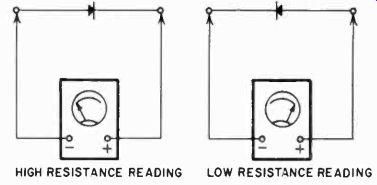
Fig. 707. The VOM can be used to check germanium, silicon and selenium diodes
and rectifiers.
A transistor is a semiconductor device. We can regard it as a pair of diodes, back to back. Thus, a transistor should have a high for- ward-to-back ratio the same as a diode, between its emitter-to-base and collector-to-base junctions. Since P-type semiconductor material has a "shortage" of electrons (a place to which the electrons will flow) the low reading should be obtained with the "+" or red prod on the collector and emitter of a p-n-p transistor; the opposite is true of an n-p-n unit. The ratio of forward and back resistance Varies all over the lot for production transistors, but for really good ones it should be better than 20 to 1. Some first-class units will measure 20 ohms one way and several megohms the other.
The forward-to-back resistance test is just a qualitative check of whether the transistor is open, shorted or normal; for a measurement of just how good the transistor is, you need more than a VOM. In a later section some of the simplest transistor checkers will be shown, using the VOM as its basic meter. At this point, you can use the VOM only to check the transistor for faults and for type.
The mystery component It sometimes happens that you will find among your components something that looks as though it might be a resistor or a capacitor or maybe even an encapsulated inductor. How can you identify this mystery part! If you check for resistance, it shows infinite, but not being sure, you would not throw it out as an open resistor.
Checking its capacitance, you don't seem to get a reading either.
What is it? Most likely it is a very, very small capacitance in the order of a few micromicrofarads, maybe even less than 1 uuf And if you remember that the reactance of a capacitor goes down as the frequency goes up, the way to discover if this is a small capacitor is to measure the ac voltage you can get through it from an audio oscillator. For 1 uuf, a 5,000-cycle frequency at a few volts should give you a very readable measurement on the low ac scale of the VOM. If the device is an open resistor, more than likely you will not get a reading at all; the capacitance of burned-out carbon ends is so small it cannot be measured with a VOM even this way.
Sometimes you will encounter a similar situation in oscillator coils. Checking out a coil, you may find that one of the terminals, even though it has a wire connected to it, does not give a reading to any other terminal. In this case you may be dealing with a coil in which a few turns of wire, wrapped around the main coil, serves as a capacitive coupling to the grid of the oscillator tube, and actually does not have a second connection.
A somewhat similar situation may be encountered in power transformers or modulation transformers, which may have what is called a Faraday shield. This is made in the form of a winding between primary and secondary, because this is a good economical way to make it, and has only one connection. A Faraday shield keeps high-frequency power-line interference from getting into whatever device the transformer may be in, or vice versa to keep the device from sending high-frequency interference out over the power line. The transformer lead to the Faraday shield is often bare, tinned, stranded wire.
Tube filaments
With vacuum tubes about the only thing you can check is continuity of the filaments. That is, without auxiliary apparatus, which we will discuss later. It is also possible to check for element shorts, but this test should be made with the tube warmed up. Use the setup shown in Fig. 708, in which the filament receives its rated ac filament voltage. The tube is allowed some time to get warm, and the VOM is then used to check one element after another. Connect one lead of the VOM to the cathode, as shown. Connect the other lead to each tube element (via the socket) in turn. As you make the connection, tap the tube gently and watch the meter.
You can use the rubber-end of a pencil, but tap the tube. Don't wallop it! If the meter reads, you have a short.
Other tube tests require more external apparatus.
Appliance repair Iii appliance repair, the VOM will be employed chiefly as a continuity tester, using the lowest ohms range.
Since most modern VOM's have also a very-high-resistance range, they can also be useful for insulation tests. The resistance to frame or ground on a motor should be at the very least several megohms, and preferably over 10. The insulation resistance of many devices will depend partly on the humidity, and thus you may read different amounts on different days but, if they are all high, there is no danger. Good insulation values are particularly important on equipment used in the bathroom and kitchen, since the user is likely to stand on a damp floor or come into contact with damp surfaces. Electric shavers, waffle irons, toasters, flatirons, portable heaters, mixers and blenders and electric frying pans should have very high insulation resistance.
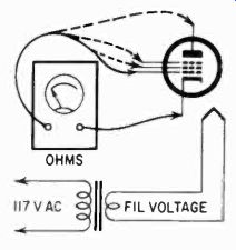
Fig. 708. Checking a tube for element shorts with the filament heated.
The VOM's ohms ranges may help locate a break in a heater element or lamp-cord. Its voltage ranges can help you locate a blown Fuse quickly. With the meter set on the 150-volt ac range or higher, you can locate the blown fuse by testing on either side of the fuse socket, with some lamp or appliance switched "on" in every circuit in the house. The fuse which has a voltage across it is the open one.
If the two connections to the fuse are not available, the fuse can be checked for continuity, but then each one checked must first be removed from its socket.
Some household appliances refuse to function properly when the line voltage is low. For example, refrigerator, washing machine or dryer motors may never quite reach enough speed to "kick out" the starting winding, overheating the motor. When unusual noises come from the appliance, such as a repeated on and off clicking noise, check the line voltage with your VOM; it may be all you need to locate the trouble.
Expanded scale for the VOM
An expanded scale means a scale which covers just a portion of the voltages you are dealing with. This is useful for observing small variations in such voltages, as a result of temperature, loading or some other factor which changes in time. The method is simple, as you can see from Fig. 709. The voltage to be checked is connected to one side of the meter, while a bucking voltage is connected on the other side. Now the meter needs measure only the difference between the two voltages, and a lower scale can be used. For example, if we want to determine the change in a 100-volt source, and we use a 67.5- and a 30-volt battery in series, we will actually be measuring 2.5 volts, and the meter scale for that range can be used. Now a change of 1 volt will result in a meter deflection of almost half-scale. This voltage change would be barely visible on the 250-volt scale which we would otherwise have had to use.

Fig. 709. Expanded (40 times) reading of variations in voltage.
Detecting small changes in direct current
The same principle can be used to observe small changes in current (Fig. 710). The bucking battery counteracts the meter deflect ion as a result of the current through the shunt, and by this trick we can use a lower range for the current measurement.
For example, let us suppose we want to measure the change in a 10-ma current. If we send this through a shunt for, say, a 100 microampere meter which has about 1,000 ohms internal resistance (a 100-mv meter, in other words), we would have to use the 10-ma range to get exactly 100 my at the meter terminals, giving full deflection. This shunt would be a little less than 10 ohms. Were we to push this current through a shunt 10 times as large, and bucked out all but 100 mv of the voltage generated across this shunt, we would still have only 100 mv at the meter, and full scale deflection. If the current changed to 11 ma, we would be generating 1,100 my, but bucking out only the same as before; in other words, a 100-mv change at the meter. You can easily see then how sensitive this system would be.
We must make sure, of course, that the shunt for the lower range is capable of accepting this larger current, and that the shunt is not so high in resistance that its inclusion is going to change the current in the entire circuit. If you make sure that the shunts can take the current, or if you are willing to use external shunts, you can in this way enlarge the sensitivity of your meter by simply making it read a difference voltage.
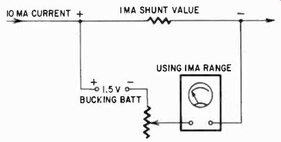
Fig. 710. Expanded (10 times) reading of variations in current.
Detecting small changes in ac voltage This could also be used for ac, provided the voltages used for the compensation were of the same frequency and precisely opposite in phase. If we are dealing with 60-cycle power frequencies, where the phase reversal can be a simple reconnecting of a power transformer winding, then we are in business-provided the change we wish to observe is not going to be materially affected by power-line voltage changes. For example, if we have a regulated ac supply and use this to feed both the device and the comparison voltage source, in the proper phase, we could use this system. But, as you see, the conditions which must be imposed rather limit this technique for ac.
For resistance-variation measurement, if we try to set up a circuit for a comparable "difference" measurement we will inevitably end up with a bridge circuit. This we will discuss in another section, for here the meter becomes part of a system, not the system subsidiary to the meter.
The VOM and you
There is quite a general tendency to regard the VOM as an instrument of very limited capabilities, particularly if the unit has a rating of only 1,000 ohms per volt. Part of this is due to the growing popularity of the vtvm with its considerably higher input impedance. But, as we have shown here, the limitations of the so-called insensitive VOM should possibly be ascribed to the user.
In this section, and elsewhere in this guide, we have shown that the VOM has a much greater utility than is generally recognized, but this utility is dependent upon the skill of the user.
No claim is made that the "out of the ordinary" uses of the VOM described in the various sections are the total sum of what the VOM can be expected to do. These simply represent a small sampling of what the VOM can accomplish in the hands of a skilled technician.
Also see: Link | --Guide to VOMs and VTVMs