AMAZON multi-meters discounts AMAZON oscilloscope discounts
Your five senses can spot defective electronic equipment on occasion. However, the senses cannot test amps, volts, ohms, microvolts , frequency, watts , peak-to-peak, waveshape, mutual transconductance, beta , bandpass response and other electronic parameters. You must have test equipment to do that. Testing is the only way you can find out if electronic components are satisfactory or not. Testing is not exactly the same as measurement. Measurements tell you precisely how many of a certain parameter are present. During a test you might need to know how many, but it's only to determine the quality of an electronic object.
Alignment is usually needed to adjust the tuning of a circuit. Alignment is also used in testing to determine if an oscillator is creating a good signal and if a circuit is also passing frequencies properly.
Testing and alignment are conducted with various pieces of equipment especially designed for the purpose. There are all kinds of special purpose test equipment, plus certain basic pieces of equipment that are universally used and used more frequently than others. These common pieces of equipment include multi-testers, oscilloscopes , tube testers , signal generators , wattmeters, field strength meters , transistor testers , and decade boxes. Then there are all sorts of probes that attach to some of these units such as high-impedance, demodulator and high-voltage types. Test equipment simply "hooks into" electronic gear and measures the electronic parameters, or they produce a signal that can be driven through the circuits. They are the sensors that permit you to examine all the activity in the circuit.
MULTI-TESTERS
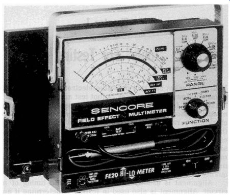
------- Sencore Model F EZO field-effect multimeter.
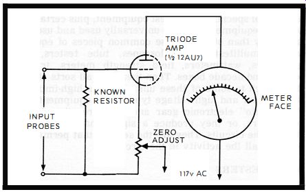
Fig. A. When a triode tube in a VTVM has a voltage input, it causes a proportional
change in the ammeter reading in its plate circuit. The triode has a large
in put impedance so circuits under test are not loaded down.
As the name implies, you can test a multitude of parameters with a multitester. Popular types are the YOM, VTVM and field-effect multitesters. The YOM is portable and battery-operated. The VTVM is dependent on vacuum tubes (Vacuum Tube Volt Meter) and must be plugged in (Fig. A).
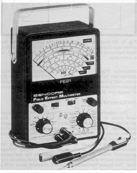
-------------- Sencore Model F E21 field-effect multimeter.
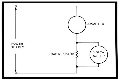
Fig. B. An ammeter in series with the load measures the amperage drawn by
the load. An ammeter in shunt with a load measures the voltage across the load
and, in effect, is a voltmeter.
Field-effect multitesters use FETs in the circuits and come battery- and AC-operated.
The VOM and FET multitester can test a wider range of parameters than a VTVM. The VOM and FET multitester can measure volts , ohms, amps and decibels. They also test AC as well as DC. The VTVM tests everything the others do, except for current. There is no amp test available on most types.
No matter how complex they appear, these multitesters are nothing more than an ammeter , voltmeter (Fig. B) and ohmmeter (Fig. C) all encased in the same package with appropriate switches to select the desired function. It is the most used piece of test equipment because it tests the basic parameters of an electrical circuit. Actual uses and fine points of usage are discussed throughout the text.
OSCILLOSCOPES
The cathode ray oscilloscope (Fig. D) is the second most used piece of test equipment. It basically provides two parameters. One of the parameters is also offered by a good multitester. The two parameters are; one, a picture of what the waveform in a circuit looks like and two , the peak-to-peak voltage level that is being viewed in the scope display.
There are two axis in the scope display. One is the horizontal, normally produced by an AC sweep voltage generated inside the scope. It is applied to the horizontal deflection plates of an electrostatically controlled cathode ray tube. The typical horizontal sweep is a sawtooth wave with a linear time base. It causes the cathode ray to be swept from left to right at a uniform rate and then snaps it back at the end of the line to begin again.
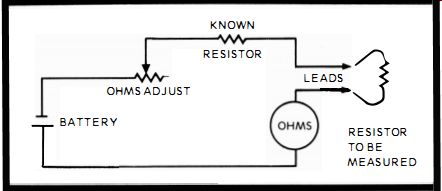
Fig. C. An ammeter in this circuit becomes an ohmmeter and ca n measure resistance
in ohms.
The second axis is the vertical sweep. The signal you want to look at is fed into the vertical input of the scope and is applied to the vertical deflection plates of the CRT. The signal causes the cathode ray to be swept up and down as the horizontal is sweeping back and forth. The resultant waveshape is the desired display.

Fig. D. A scope displays circuit waveforms and the amplitude in p-p volts
when ca librated.
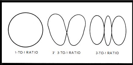
Fig. E. A Lissajous figure scope display reveals the ratio between the input
voltage frequencies.
The horizontal sweep can be varied in frequency and also in waveshape by controls on the scope. The horizontal sweep ca n also be turned off internally and an external horizontal waveshape applied to the horizontal sweep to produce various types of displays. Therefore, the waveshape is available for close analysis and can be the positive indicator of missing or distorted waveforms.
The peak-to-peak voltage of a waveshape can be read directly on the scope screen. Many oscilloscopes provide various controls and even an AC voltmeter, so the exact peak to-peak value can be easily read. Even on the most economical scope, the peak-to-peak value can be computed easily. Simply take a reference display, such as the 117-volt, 60-Hz line current, and inject it into the vertical input of the scope. Mark the amplitude of the displays as 165 volts peak-to-peak (117v is the RMS value-the effective value ). Make the marking directly on the scope face, either with a transparent sc ale or with a marking pencil. Then compare any other display in relation to the 165-volt scale you have just made.
If you apply sine-wave signals to both the vertical and horizontal inputs of a scope, with all, internal sweeps turned off , predictable figures will appear. This is probably the easiest way to gain a good idea of what you are doing with the scope. These figures are named Lissajous figures (Fig. E). The display they produce is dependent on their relative amplitudes, frequencies and phases. When the phase relationship is exactly 90 degrees between vertical and horizontal and the amplitudes are about equal, the frequency ratio can be read directly from the appearance of the pattern .
When both the frequencies are identical , the vertical will sweep up and down at the same time the horizontal sweeps back and forth , both in a sine-wave fashion. The resultant picture of this one-to-one frequency ratio is a perfect circle.
When the vertical input is doubled in frequency in relation to the horizontal, the vertical will appear twice as the horizontal sweeps once. The display will look like a figure 8 lying on its side.
When the vertical is tripled in frequency in relation to the horizontal, the vertical will appear three times as the horizontal sweeps once. The display will have three points along the top and bottom and just one loop along the two sides.
If you consider the number of loops along the top and the bottom as the vertical part of the ratio and the number of loops along the side as the horizontal part of the ratio, you can easily calculate a Lissajous figure.
The Lissajous figures are more than just electronic exercises. Using the 60-Hz line frequency, which is a known constant, you can measure frequencies in the audio range by comparing the Lissajous loops you produce on a scope display, using the scope's internal sweep.
SIGNAL GENERATORS
Signal generators are nothing more than test oscillators. They produce audio frequencies, RF frequencies, marker frequencies and so forth. In the audio range, most audio oscillator s provide a variable frequency and amplitude output ranging between 20 and 20,000 Hz. A good one produces square waves as well as sine waves. In the RF range , most generators cover a range between 85 kHz and 40 MHz for AM, FM and CB work. Some produce 19 kHz and 38-kHz signals for multiplex stereo work and TV signals for RF , IF and FM carrier waves. RF generators produce marker frequencies that are high in amplitude and very narrow in width, and so forth, as well as modulated RF signals. Sweep generators provide variable sweep widths up to 12 MHz. The designs are infinite and you must choose your signal generator to suit the job you want to do with it.
The test oscillator can be almost any type. It simply has to produce a signal from an RC, LC or crystal-controlled oscillator. The oscillator signal can be injected into circuits to signal trace or align them. A test oscillator will aid in measuring such parameters as frequency, by comparison on a scope face, and frequency response of a circuit by its appearance on the scope face. It's also invaluable in signal tracing, using either a multitester , speaker or TV CRT as an indicating device. The gain of a stage and the overall gain of several amplifier stages can be measured accurately by taking output readings and comparing them to input readings and various test points along the signal path.
POWER METERS
A power monitor , such as the Sencore PM 157, measures watts. The power in watts is the result of multiplying current times voltage. The power meter assumes an input voltage of 117 volts and based on this line voltage, reads amperes directly. With a voltage other than 117 volts, the actual power is computed by an accompanying conversion table.
FIELD STRENGTH METERS

------- Sencore Model SM152 sweep and marker genera tor designed for
TV sweep alignment.

------ Marker generator, Sencore Model SM1 58, provides signals
for TV IF , chroma and RF alignment.
------ Sencore PM157 power monitor measures line voltage, current and watts .
The typical field strength meter has one meter with one scale on it. The scale is graduated in microvolts and decibels , although it is primarily used to measure microvolts. The decibel level is a relative measurement. It was decided that 1000 microvolts across 75 ohms is zero decibels (db). All readings under 1000 microvolts are negative decibels and all readings above are positive decibels. The decibel scale is logarithmic.
The field strength meter is a very simple receiver tuned to the frequencies you want to test. Instead of a speaker or CRT output , a meter is used. In fact, some field strength meters provide a speaker output in addition to help verify the signal you are tuned to.
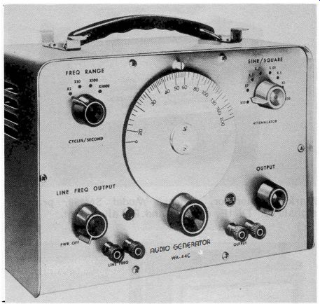
---------- RCA Model WA-44C audio generator produces sine and square
waves.
TUBE TESTERS
It goes without saying that the best test for a tube is a direct substitution of a known good tube. As a result of this truth, it is a fact that lots of busy electronic shops do not even have a tube tester on the premises. Others do own one, but they are in a corner covered with dust. When a tube tester is used in a service shop, it is usually for one reason. A tube is suspected as defective and there is no known good replacement near at hand. The tube tester is then used to determine whether a tube is good or bad.
Emissions Test
Most testers provide a simple cathode emission test. Whether the tube is a diode , triode , pentode or heptode, it is tested as a diode. For instance, in a tube with a control grid and screen grid, the two elements are tied to the plate (Fig. F). Then, a DC voltage is placed on the plate and current is drawn from the cathode.
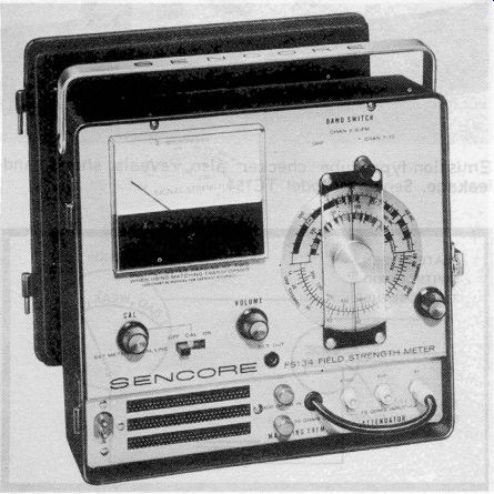
--------- Field strength meter for all TV bands and the FM broadcast band.
Sencore Model FS134.

----------- Emission-type tube checker also reveals shorts and leakage.
Sencore Mode l TC1 54.
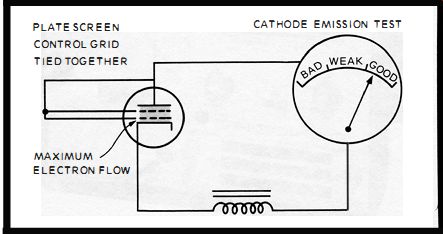
Fig. F. Most tube testers simply measure cathode emission. It follows that
other characteristics probably are good if the cathode emission is good .
Without the valve action of the control grid, the cathode runs wide open. The plate absorbs all the cathode current. A DC meter in the plate shows whether the cathode emission is strong, moderate or weak. A strong current flow deflects the meter into the good region. A moderate flow places the needle into the weak, and little or no current puts the needle into the bad section. Green, yellow and red display colors help confirm the good, weak and bad on the dial face. This test, if prolonged, can warp the tube elements and strip the cathode of its emission material.
While this test is far from ideal, it is an adequate go-no go test and is the one performed. It has enough merit to be used in the exceptional cases when the direct substitution test cannot be performed.
Gm (Mutual Transconductance) Test
Another type of tube tester occasionally found in a service shop actually measures Gm in a tube, in a rough manner. Gm is the ratio of the amount of control grid voltage needed to cause a certain change in plate current. In a Gm tester a signal, separate from the applied DC bias, is applied to the tube being tested (Fig. G)' This is in triodes, pentodes , etc. , not in diodes.
The control grid signal, which is known, produces a change in the plate current. The amount of change, measured in microamps is divided by the control grid signal voltage. The resultant is displayed on the meter in the plate-circuit. It is measured in micromhos, the transconductance.
Gas and Short Tests
In most tube testers, the gas and short tests are performed simultaneously. During the test, a high potential voltage difference is applied to different elements of the tube. If there is any gas in the tube, or the control grid draws any current, or if any current flows between elements , an indicator either reads the current in microamps or a neon light winks on.
There is an aluminum oxide coating of insulation between the heater and cathode. If it breaks down and allows current to flow, even in minute amounts, a H-K short is revealed. Most testers won't show anything until at least 100 microamps pass from heater to cathode. While this test is also rough, it does provide a certain amount of service information and will on occasion pick out badly leaking tubes.
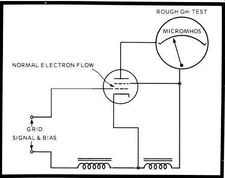
Fig. G. Some commercial testers actually provide a rough Gm test with this
basic circuit.
The principle behind tube testers is valid though not unerring. While there are all sorts of tube parameters such as amplification factor , plate resistance , interelectrode capacitance, plate current, grid current, typical element voltages and so forth, in addition to Gm and cathode emission, it is assumed that if the cathode emission, shorts and gas tests are good, the rest of the tube is probably OK, too .
TRANSISTOR TESTERS
While tube testing is simple , even on the most complex tester, transistor testing is quite complicated. While all tubes operate around the cathode-to-plate electron flow, transistors perform in a multitude of ways. The only real complication to tube testing is the great number of tubes all with different pin numbers. The tube tester solves this complication with numerous tube sockets and a switch. The pin number complication doesn't exist in transistor testing. There is only E, B and C in a bipolar transistor and S, G and D in a field-effect transistor. Transistor s, however, make up for the lack of connection complications by demanding accurate parameter testing instead of the simple cathode emission type test a tube needs. While a tube is easily substituted in tube sockets, most transistors are best tested in circuit and have to be carefully unsoldered to remove them from the circuit.
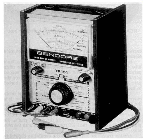
------------ Sencore Model TF15 1 transistor tester designed to check bi-polar
and field-effect transistors.

---------- RCA capacitance-resistance substitution decade box.
Bipolar transistors have to be tested for DC and-or AC beta. DC beta is the current amplification factor and is the ratio of collector current divided by the base current. AC beta is the ratio of change in the collector current divided by the change in the base current, while holding the collector voltage constant. This current parameter is used in conjunction with bipolar transistors because they are current amplifiers.
A second parameter needed in analyzing a bipolar transistor is the leakage current flow in microamps between the collector and base. It's called Icbo. These two parameters can be obtained only with a good transistor tester. Icbo means current I, between the collector c and the base b with the third element left open 0, In field-effect transistors, which are voltage devices like a tube , not current devices like a bipolar transistor, the main parameter needed is Gm, the same as a tube. The second parameter, Igas, which is the leakage current I between the gate (G) and the source (S) with the third element (S ) shorted to the second element, the source.
A third parameter of an FET is Idss , the zero bias drain current. It is something like cathode emission in a tube. It is the amount of current I that flows from the drain D to the source S, with the third element, the gate, shorted to the second element, the source S. With the gate shorted to the source, it's like a tube tester shorting the control grid to the plate. Just like the tube , the FET runs wide open with the zero bias.
Another transistor test check is the oscillation capability and how high in frequency it can oscillate. The ordinary transistor tester does not usually provide the test, but a special oscillator circuit can be put together as shown in the text.
DECADE BOXES
A largely ignored testing technique is that provided with decade boxes. Perhaps it is ignored because it is so simple and when a decade box pinpoints a bad component it 's almost like cheating. No technological foreplay is performed. Yet the decade box technique is quite accurate and can perform a test something like the direct substitution of a tube. With a decade box you can introduce substitutes for resistors, capacitors , diodes and filter capacitors. Also , you can add and subtract resistance and capacitance from a circuit.
A decade box is nothing more than a group of commonly used resistors , capacitors and rectifiers , mounted in a convenient box. You can select values at will by the turning switches and pressing buttons. Yes , individual components could also be used, but the convenience of the decade box and its clip leads save all kinds of time. By adding the decade box to your bench and using it frequently, another full dimension of testing by substitution is available.