AMAZON multi-meters discounts AMAZON oscilloscope discounts
No. 12 : DISCRIMINATOR ALIGNMENT-FM RADIO
During an FM radio repair made on the bench rather than in the field, it is a good idea to quickly align the discriminator. It is a rare radio indeed that will have a perfectly aligned discriminator after a few years of service. Even though other troubles must be corrected , the end of the repair should be a check of the receivers alignment. A misaligned discriminator causes loss of volume, blurred audio and possibly squeals and buzzes.
In order to properly set up the discriminator curve, you really must see it, rather than watch a VTVM produce a reading of the peak-to-peak output voltage. A sweep generator and a scope are needed. The scope is hooked across the volume control (Fig. 12A). The signal generator is set at the IF, which in most FM radios is 10 .7 MHz. The IF is swept at 200 kHz in most radios, but be sure to check the manufacturer's service notes, since on occasion the IF is not 10 .7 MHz and the sweep is not 200 kHz. The generator cable is attached to the input of the limiter, which is found before the discriminator; if the discriminator is actually a ratio detector, the generator input is attached to the input of the last IF stage. The limiter is an IF stage that performs limiting duty in addition to IF duty.
Whether the circuit is a true discriminator or a ratio detector , the alignment procedure is similar. The local oscillator is turned off by attaching a short across the oscillator coil. That way no heterodyning takes place and no 10 .7-MHz signal can be developed to interfere with the signal generator input signal. All equipment is turned on and warmed up for a good half hour. The volume on the radio can be turned all the way down if you wish to avoid distract ion. The scope displays the signal developed across the volume control to drive the vertical input. This is the actual detected AF produced in the sweep section of the generator. The generator is sweeping 200 kHz 60 times every second at a certain p-p voltage. The scope uses its own internal sweep for horizontal deflection. If you set the scope horizontal sweep frequency, you'll see a single line diagonally across the scope screen as the detector output goes from minimum peak to peak to maximum in one of the 60-Hz intervals (Fig. 12B). This is the well known discriminator curve.
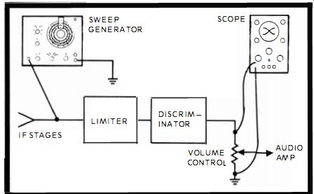
Fig. 12A. Discriminator alignment hookup is simple and requires only a sweep
generator and ordinary scope.

Fig. 12B. The discriminator curve is a picture of the generator sweep as it
appears across the volume control.
In the discriminator transformer there are two cores. One slug , the secondary, adjusts the center frequency of the curve.
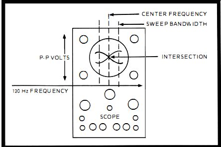
Fig. 12C. A trick to achieve closer discriminator alignment is to double the
scope's horizontal frequency.
The center frequency is 10.7 MHz before detection, but after detection it is the zero point between the minimum sweep and the maximum sweep. You adjust the secondary slug until the center frequency looks good and symmetrical between the minimum and maximum points. Then, you can adjust the primary core by watching the linearity and shape of the curve.
It approaches an S shape lying over on its side at about 45 degrees. If you understand what the discriminator curve represents, you can take it one step further and employ a trick to get an on-the-nose alignment. This is accomplished by changing the horizontal scope sweep to 120 Hz. This puts two segments of the response curve on the scope face , one on top of the other , forming an X. There are now two slanted S curves , one in each direction. When the secondary or top slug is adjusted the intersection of the two curves will move. They should be set where they produce a symmetrical X with the intersection at dead center (Fig. 12C). When the primary or bottom slug is adjusted, the curves are straightened out, resulting in a good linear X. At the best looking X, the primary is set on the nose. Actually, the secondary slug sets up the proper phase of the signal. When the slug places the intersection of the X at the linear center , the zero part of the curve is right on the center frequency. This places the discriminator right on phase where there is equal peak-to-peak voltage on both sides of the center frequency. Ratio detector alignment is practically identical to discriminator alignment. You could set the sweep a bit further out than that used for discriminator alignment so the curve will tail off quickly and clearly delineate the ends of the curve. Also , you could purposely detune the secondary so the linearity shows up clearly as you tune the primary. Otherwise, the alignments are identical.
No. 13: IF-LIMITER ALIGNMENT

------------- Stereo signal genera tor, RCA Model WR-52A.

Fig. 13A. The Q of an IF transformer can be lowered to permit additional bandwidth
by adding resistance.
FM stations are permitted to transmit a deviation of plus or minus 75 kHz in comparison to the AM maximum of about 15 kHz. An FM radio takes advantage of this wide frequency swing by passing through its IFs a band of about 150 kHz. Not all FM radios do this, but even the cheapest ones pass at least 50 kHz. A check of the bandpass capabilities of an FM radio is needed quite often during servicing. If a radio is not passing the IF it was designed for , and an alignment check shows that it can't pass those frequencies , the stage and probably the IF transformer is indicated as defective. This is a valuable service technique after DC-resistance tests have failed to produce any results. There are quite a few different designs around in commercial receivers. Each has its own particular detailed alignment which is predicated on the design. You must consult the radio service notes for the actual alignment since there are entirely different types of bandpass requirements in the different designs.
In an inexpensive FM radio where there are only one or two IF stages , the 50-kHz bandpass is achieved by lowering the gain of the stage which flattens out the response curve skirts and lowers the peak-to-peak voltage of the flattop. The most common way of doing this is by using an IF transformer with a resistor in parallel with the LC tank circuit (Fig. 13A). The resistor, according to its value, lowers the Q of the tank , causing the wider, lower response curve that permits the broader bandpass. In a more expensive FM radio, there are more IF stages and the bandpass can be made as high as 250 kHz. In these cases , the radio usually employs a stagger-tuned IF system, exactly like the TV stagger-tuned IF and it is aligned in the same way. (See the TV stagger tuned IF alignment discussion. )
Even though the wide band IF has its particular quirks according to the actual receiver, there is a general alignment procedure. If there is a limiter stage , peak alignment adjustments are made by attaching a scope or VTVM across the limiter input and adjusting the IFs for maximum voltage output.
The sweep generator is attached into each IF input in turn (Fig. 13B)' The sweep is set for whatever the manufacturer calls for from 50 kHz up. Each stage is aligned by adjusting, first, the secondary slug and, second, the primary slug for peak voltage. Each stage is aligned all the way down to and including the mixer. The local oscillator is turned off, as in all the other similar alignments , by shorting out the oscillator coil. Another way is to connect the VTVM across one side of the ratio detector. You'll see either a positive or negative voltage ; it doesn't matter which. Then, align all the IFs in turn until you get the best available peak reading. This reading will be a result of the best response curve.
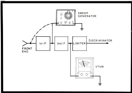
Fig. 13B. The limiter in an FM radio can be aligned by adjusting for the pea
k voltage amplitude on a VTVM.
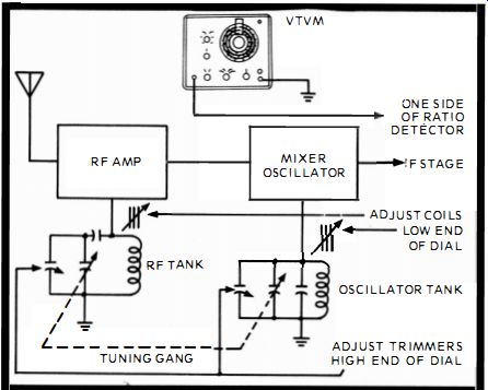
Fig. 14. The coil s in the FM front end adjust the low-end dial setting while
trimmers adjust the high end.
No. 14 : RF-OSCILLATOR ALIGNMENT
The FM tuning dial is very critical and many dials read in correctly to some degree. It's best not to try to restore precise settings. Simply note that they are slightly off. Alignment should be performed, though, if one end of the dial or the other has lost gain. Then , alignment is necessary. When you finally decide to do an alignment, remember that the smallest turn of a screw is critical.
Do not short out the oscillator coil. The oscillator must be running since it is one of the circuits that will be aligned. The sweep generator is turned on and set at the FM frequencies between 88 and 108 MHz. The sweep is set at the manufacturer's recommended bandwidth, which is any where from 50 kHz to 300 kHz. The VTVM is placed across one side of the ratio detector and either a negative or positive voltage is obtained.
The radio is tuned to 90 MHz and the sweep input set at the same frequency. Then the coils in the converter and RF circuits are adjusted for maximum detector voltage. This sets up the low end of the dial. Next, the radio and generator are tuned to 107 MHz. The two trimmer capacitors are adjusted in the converter and RF tank circuits. At maximum voltage , the high end of the dial is set up. In both cases, adjust the converter tank circuit first and then the RF tank circuit (Fig. 14 ).
FM CONVERTERS
There are all kinds of electronic gadgets around the home and one such interesting piece is an FM converter that attaches to a TV set. The FM band (88 through 108 MHz) lies directly above TV Channel 6. In other words , Channel 6 ends at 88 and the FM band immediately follows. It became quite obvious to technicians that FM stations could be received by the average TV set. In fact, old-time TV receivers with continuous tuning through the FM band were also FM receivers , numbers , dial and all. A few manufacturers built actual converters , resembling the UHF converter. Early models used tubes and more recent ones use transistors. Somewhat like the UHF converter, the FM converter has a mixer-oscillator stage that converts FM signals from the 88-108 MHz range down to 63 MHz or 69 MHz which is Channel 3 or 4's center frequency.
The outdoor antenna is detached from the TV terminals and attached to a pair of input terminals on the converter (Fig. 15 ). A short length of lead-in is run from the output terminals of the converter to the TV set. When the converter is off , the two terminals on the converter are shorted together by a function switch and the signal is passed as if the converter were not present. When the converter is on, the function switch attaches the antenna input to the mixer oscillator and turns on the power in the converter. The mixer receives the antenna input and the oscillator input. The two frequencies mix and the output is two frequencies simulating the video and audio of either Channel 3 or 4, whichever is blank in the area. (Even if neither are blank, the converter output overrides the TV signal. ) The video simulator signal is unmodulated and the audio carrier is modulated. The generated video and audio carriers are beat together and produce the 4.5 MHz required in the TV sound section. The FM signal then is converted into a TV-like transmission. It enters the TV tuner as a Channel 3 or 4 signal, becomes an IF of 44 MHz and is passed into the video section.
A 4.5-MHz pickoff transformer injects it into the TV audio circuits .
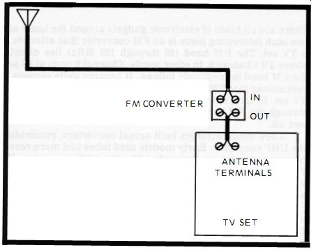
Fig. 15. An FM converter is attached to the TV antenna terminals exactly like
a UHF converter.

-------- RCA WR-50BA Mini Chroma Bar genera tor designed for color signal
production.

Fig. 16. An FAA converter uses one transistor that does the job of tuned RF
, oscillator and converter.
The limitations are minor. The fact that the FM transmission has a band-sweep of plus or minus 75-kHz and the TV reproduces only plus or minus 25-kHz is not noticeable in the low-frequency TV speaker output. The fact that the TV has all those tubes burning just for the FM sound is forgotten, just like the instant-on feature of a TV, which also keeps tubes burning.
The light on the TV screen can be extinguished with the brightness control. This stops all CRT high-voltage current drain in black-and-white TVs. With color TV, however , there is still current drain in lots of regulator circuits. Nevertheless , these gadgets are found in homes and need testing on occasion. The tests are also applicable to similar type equipment. There are other forms of converters that operate with similar circuits. Only the frequencies are changed. Be sure to have service notes for correct frequencies. FM converters are found with both inductive and capacitive tuning. Inductive tuning at these frequencies is accomplished with two conductive rods and a moving shorting bar. The rods are attached into the input and output circuits of the mixer oscillator. The RF input is tuned and the oscillator is made to track with the RF tuning. The tuning capacitor is quite small and it, too, is connected into the input and output of the mixer oscillator. There are two sections to the ganged capacitor and the sections track with each other.
The output of the converter (Fig. 16 ) is fed to the TV set through a TV type balun coil (balanced transformer ). The twin-lead has one side attached to the bottom of the transformer and the other side to the top. The local oscillator can be tuned through a range of a little over 6 MHz. A frequency between 30 .83 and 37.5 MHz is chosen for oscillator operation. The RF is tuned to receive 88 to 108 MHz, the FM band.
The two signals are mixed in the circuit and a number of frequencies are produced. Among them are the difference between the two frequencies and the second harmonic of the oscillator. If you consider the converter tuned to 108 MHz, the two resultant frequencies are :
Tuning 108.0
Oscillator 37.5
Difference 70.5
Osc : 37.5 x 2 equals 75.0, the second harmonic. Notice the two frequencies are 4.5 MHz apart. The 75.0 is a video simulation and unmodulated. The 70.5 is an audio carrier simulation and is modulated. The TV can easily use this mixture of frequencies and produce FM sound.
If you consider the converter tuned to 88 MHz, the two resultant frequencies are :
Tuning 88 .00
Oscillator 30 .83
Difference 57 .17 30 .83 x 2 equals 61 .76, second harmonic Again notice the two frequencies are just about 4.5 MHz apart. The discrepancy of 0.09 is negligible.
61 .76
57 .17 4.
59
0.09 Discrepancy
The 4.5-MHz inter carrier sound frequency is needed to enter the TV sound system (Fig. 17).
No. 15: FM CONVERTER OSCILLATOR ALIGNMENT
The oscillator is aligned for the center frequency of the FM band, 88-108 MHz, at 98 MHz. A signal generator is attached to the input antenna terminals. A matching pad , using two 300 ohm resistors and two 1K resistors , matches the generator to the 300-ohm input. The two 300-ohm resistors are in parallel, the two 1Ks are in series , forming four sides of a block (Fig. 18 ), The output of the converter is attached to a 44-MHz IF type TV, and the TV is tuned to the indicated channel, either three or four, according to what the converter calls for. The signal generator is set at 98 MHz, with an output of a 100 or so microvolts , with modulation not more than 50 percent. The converter's dial is set at exactly 98 MHz. The oscillator coil is tuned until the signal generator's modulation is heard from the TV.
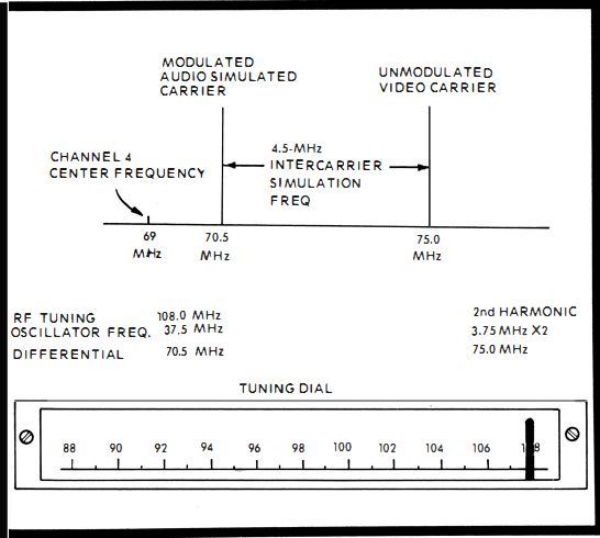
Fig. 17. An FM converter simulates a TV signal so the audio will be picked
off by the 4.S-MHz intercarrier takeoff coil.

Fig. 18. An FAA converter is easily aligned by attaching a signal generator
and adjusting the oscillator coil.
No. 16: ALIGNING THE FM CONVERTER RF INPUT
Once the oscillator is set for the FM center frequency of 98 MHz, the signal generator output is slowly reduced until some static begins to mix with the generator signal. Set the generator at an output where the signal can be heard but is at its weakest. The RF coil trimmer capacitor (Fig. 16 ) is then tuned for peak audio from the TV. To obtain even greater accuracy, reduce the generator signal until it's barely heard and again peak the RF trimmer.
No. 17: ALIGNING THE FM CONVERTER IF OUTPUT
The intermediate frequency (IF) produced by the FM converter is, for example , Channel 3. Both a video carrier and an audio carrier are placed on the FM converter-generated Channel 3 carrier. In the TV tuner, the signals are heterodyned once more to produce the 40-MHz TV IF carrier. The converter has to deliver as much usable signal as possible over the FM band. Therefore , adjust the IF output coil for maxim um sound from the TV picture all up and down the FM band. Align the coil for peak performance at 88, 98 and 108 MHz by tuning the converter dial. Settle for the best compromise coil position.
No. 18 : ROUTINE TESTING OF THE FM CONVERTER
If the TV set is working fine on all channels, including 3 and 4, yet the converter is not producing any output , there is trouble in the converter. Common problems are due to poor connections , weak batteries and transistor failure. The rest of the components get practically no mechanical or electrical stress. Of course, any of them can short , open or leak, but in a well made converter it's unlikely. Since there is one stage, no further isolation of trouble is practical. Make routine DC voltage and resistance tests on all the components one by one. Keep the unit away from constant heat, such as that from the TV set or a nearby radiator. The heat can cause thermal problems in the transistor , producing drift or failure .
No. 19: CHECKING STEREO SEPARATION-MULTIPLEX
Whether you are an audiophile or not, it is difficult to determine by ear whether there is excellent, good , fair or poor stereo separation in your FM multiplex radio. When the radio is not producing the type of "solid" sound that it was, you can check to see if it is your ears or the instrument.
A typica1 good test unit is the Sencore Channelizer stereo generator. The test piece puts out a test stereo signal and a 19 kHz pilot signal. The signal is then fed into one channel , either right or left, of the stereo unit. The amount of that test signal that appears in the other channel-where it is not supposed to be-determines the quality of separation. The actual separation in a receiver is never 100 percent. There is always some mixing. Excellent separation exists when the ratio is 30 to 1, which is measured at 30 db. Good separation is 10 : 1 which is 20 db. Poor separation, though still listenable, can be as low as 3:1 or 10 db.
For the test, the RF cable from the Channelizer is attached to the FM antenna terminals. The radio is tuned to 100 MHz. A 1-kHz note will emanate from the radio. The left input is attached to the left speaker output and the right input is attached to the right speaker output. The balance and volume controls are set and the output meters in the unit are set at the REF line. Then , one channel is turned off and the 19-kHz signal turned on. The db separator is read directly on the respective meter (Fig. 19 ).
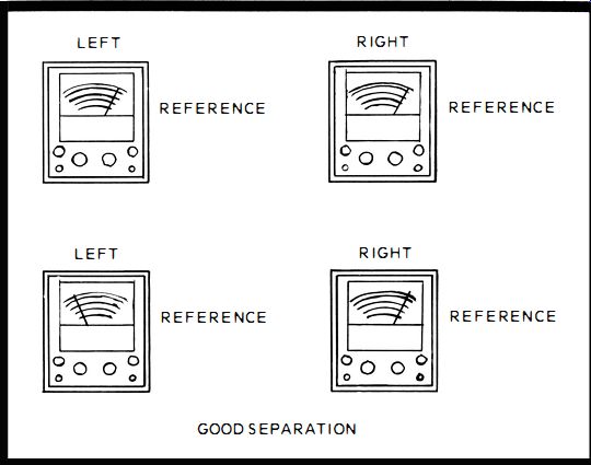
Fig. 19. Separation is indicated on the stereo test meters when the left-
and right dials read differently.
No. 20 : CHECKING CIRCUIT PHASE
Quite often the stereo effect is not achieved in an FM multiplex receiver and the cause is not readily apparent. One of the causes could be improper phase due to receiver misadjustment. At any rate, the phase should be checked to be sure it is not contributing to the poor stereo effects. The Sencore Channelizer is an excellent text unit for checking speaker phase quickly. The RF signal is attached to the antenna terminals. The left speaker leads are attached to the left speaker output on the radio and the right speaker leads attached to the right speaker output of the radio. The connections should be double checked for accuracy.
The Channelizer and radio are turned on. The receiver volume and balance are adjusted until the two meters are both reading at full scale on the REF line. A normal signal is coming through, so both outputs are producing the exact signals. The left signal from the Channelizer is turned off. The left meter reading should show a drop. If it does, the internal phase of the radio is correct. Should the right meter show a drop and the left meter does nothing or very little, the receiver has been somehow misadjusted in phase close to 180 degrees (Fig. 20 ). Probably the multiplex section of the receiver is severely out of adjustment and a complete multiplex alignment is now necessary. First, double check the left and right speaker connections before doing the multiplex alignment .
No. 21: MULTIPLEX CIRCUIT ALIGNMENT
Poor stereo separation, improper circuit phase, and simply the need to make sure the multiplex is correct to eliminate the stage as a source of trouble, are among the reasons for a multiplex alignment job. Sometimes the multiplex circuits develop subtle troubles like a shorted turn or two in a coil that can be pointed up only when an alignment will not take.
The Channelizer acts as a multiplex signal genera tor and the scope or peak-to-peak scale of the VTVM acts as the indicating device. The Channelizer is attached to the antenna input and the radio's speaker outputs are attached to the left and right meters , respectively. The left and right signal switches are turned off and the 19-kHz pilot signal set on at 10 percent.
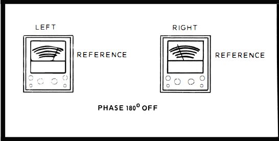
Fig. 20. The phase of the stereo signals ca n be tested with a pi lot signal.
Opposite readings mean opposite phase.

Fig. 21. Multiplex alignment requires a stereo generator input and a VTVM
indicating device.
The scope or peak-to-peak scale is attached across the secondary of the 38-kHz transformer (Fig. 21). Find the 38-kHz amplitude adjustment (not the 38-kHz phase adjustment) and set it for a peak reading in the scope or VTVM. Look for a 19 kHz amplitude adjustment, too. If there is one , adjust it for peak readings. Then, turn on the left signal switch. Find the 38 kHz phase adjustment this time. Adjust the phase for maximum reading on the left meter and a minimum reading on the right meter. This gives you separation which is part of the multiplex circuit alignment .
No. 22 : MULTIPLEX CIRCUIT "LOCK-IN " ABILITY
Confusion is prevalent concerning the separation capability of a stereo receiver. It is not unusual for good separation to exist on a strong local channel ; however, weak channels show little or no separation. One of the reasons for this is misalignment of the 19-kHz or 38-kHz amplifiers (Fig. 22 ). If the alignment is way off, only the very strongest stereo stations will show some separation. If the circuits are slightly out of alignment, only the very weakest station will not have separation.
The stereo indicating light usually will provide the suspicion that stereo signals are not being separated, because a known stereo station won't light the bulb. The Sencore Channelizer will provide a fast, accurate test by substituting output meters for speakers and producing a variable gain pilot carrier at 19 kHz. The RF cable and meters are attached to the stereo unit. The two receiver channels are balanced. Then the left signal switch is turned off and the pilot set at 10 percent. The separation is noted on the left meter.
With the pilot turned off, both meters will read at the same level. Then the pilot is returned to five percent. If separation is again attained, the 19-kHz and 38-kHz amplifiers are tuned properly and exonerated. If there is no separation, the amplifiers are detuned and require alignment.
No. 23 : MULTIPLEX CIRCUIT CHECK
When the multiplex feature of a radio stops working, but FM signals are still coming in loud and clear, all the signal carrying circuits , except the individual audio Land R, become suspect. The multiplex could be lost in the RF-IF detector area if a defect occurred that reduced the bandpass of these circuits drastically. The multiplex signal contains frequencies up to 53 kHz. All those frequencies have to be passed. Ordinary FM needs only about 15 kHz. A defect could lower the bandpass , allowing the ordinary FM channel through but not the multiplex.
On the other hand , the RF-IF detector area could be fine , but a defect in the multiplex section could mix L and R together and ruin the multiplex effect. It is useful and time saving to isolate the trouble to one or the other of the circuits. The Sencore Channelizer can accomplish this test by providing a signal that can be injected directly into the multiplex sect ion , bypassing the RF-IF detector section. Thus, in a receiver with a separation problem on all channels, should separation suddenly occur, the multiplex circuits are cleared and the blame put on the RF-IF detector area. Should the separation still be nonexistent, the trouble is probably not in the RF-IF, but in the multiplex section.

Fig. 22. The stereo multiplex transmission covers a large part of the available
75-kHz allowable bandwidth.
To effect the test, the speaker leads from the Channelizer are attached to the receiver speaker outputs. Care is taken to attach the wires to the correct terminal. The leads are taken from negative signal jack marked Stereo Signal and the positive jack also marked Stereo Signal. The negative lead is , attached to the ground of the radio and the positive lead is attached to the input of the multiplex section. This could be the detector output.
The Channelizer's left and right signal switches are turned on, the radio is adjusted for medium volume. The radio balance controls are adjusted until both meters read on the REF line. The pilot is cranked up to 10 percent and the left signal switch is turned off. The left speaker meter indication will drop off, while the right will remain at the same setting on the REF line. The channel separation is noted on the left meter. It's a good idea to make a pencil notation of it.
The stereo signal leads are then removed from the receiver and the RF cable is attached to the input of the radio.
The channel separation is again noted on the left meter. If the reading is the same as it was when the stereo signal was applied to the multiplex input, the multiplex section contains the trouble. If the separation is worse, the trouble is in the RF–IF detector circuits. The multiplex section, if indicated, could be out of alignment, which is the next step. The RF-IF , if indicated, could have a reduced bandwidth. A sweep generator is used to check the bandwidth.