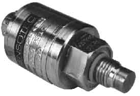
 above: A 0-5000 psi pressure transducer from Sensotec |
Load cells have been integrated directly into a number of pressure-sensitive
devices such as transducers and transmitters. The pressure transducer
is a device that can be threaded directly into a hydraulic or pneumatic
line and read the pressure of the system. The figure on the left shows
an example of a pressure transducer that has a capacity to measure
pressure between 0-5000 psi. These sensors are available in pressure
ranges from 0-50 psi through 0-1500 psi.
The typical output for this type of sensor is rated like the load cell
at 2 mV/V with exciter voltage of 10 volts. This makes these types
of sensors easy to interface with input modules for programmable logic
controllers (PLCs). |
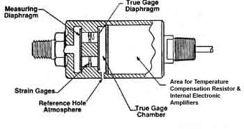
| The figure on the right shows a second type of sensor that uses strain gauge and load-cell technology that integrates a load cell beam with a diaphragm pressure sensor. The sensor is mounted (threaded) in a pressure line where the force of the fluid changes the position of the diaphragm. A beam is mounted so that it's deflected when the diaphragm changes position. Strain gauges are mounted on the beam similar to a load cell where they can monitor the change of position of the beam as force from the diaphragm is transmitted to it. The main advantage of this type of sensor is that the chamber that measures the pressure does not need any O-rings or seals since a thin metal diaphragm is used. This also allows pressures up to 5000 psi to be accurately measured. The feature that makes this type of sensor so useful is that the exciter voltage can be 12-35 volts dc, which provides an output signal of 4-20 mA. The mA signal is preferred over the mV signal because it's not susceptibility to transient or induced voltages. The 4-20 mA signal is easily interfaced to a PLC, analog input module, display (meter), or recorder. |  above: A pressure transducer that is used to measure high pressure. This type of sensor integrates a load cell with a pressure diaphragm. |
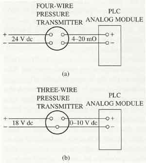
 above: (a) A diagram of a four-wire pressure transducer. The transducer has a 24 volt dc power supply and the transducer produces a 4-20 mA signal for a programmable logic controller (PLC) analog module. (b) A diagram of a three-wire pressure transducer. The transducer has an 18 volt dc power supply and produces a 0-10 volt signal for a PLC analog module. |
The figure on the left shows an example of two pressure transducer electrical diagrams, The first electrical diagram shows a four-wire sensor with a 24 volt dc supply voltage and a 4-20 mA signal that is sent to a PLC analog input module. The second electrical diagram shows a three-wire sensor with an 18 volt dc supply voltage and a 0-6 volt dc output voltage. All of the pressure transducers and pressure transmitters must be zeroed and spanned when they are installed so they accurately represent the minimum and maximum signals. The zero and span circuitry is provided through op amps that are used in the electronic part of the device. |
Prev. Page: Connecting Strain Gauges in Circuits | Next Page: Industrial Scales and Weighing Systems
Related pages: Pressure Transducers: Types and How To Select | Millivolt Output Pressure Transducers | Load Cells | Flow Meters