The isolation of troubles in individual stages is basically the same regardless of the type of stage in question. Once the defect is known to be in a certain stage, voltage and resistance measurements must be made. The information gathered by making these measurements will, in most cases, pinpoint the trouble to a particular part.
General information on voltage and resistance measurements is given next. In the several paragraphs that follow, those on voltage and resistance measurements are examples of isolating defects in various types of stages used in old-time receivers.
VOLTAGE MEASUREMENTS
The usual procedure is to make the voltage checks first. This will locate the general area of the trouble. When an abnormal voltage condition has been found, the power must be turned off and resistance checks made to determine a short or an open circuit.
In most receivers, voltage measurements are made with the negative lead of the voltmeter connected to chassis ground. The positive terminal is then connected to the points to be measured. In this way, all voltages that are positive with respect to the chassis are measured. If a voltage to be measured is negative with respect to ground, the positive terminal is grounded. If an electronic multimeter is being used, the common terminal is left connected to the chassis and the polarity-reversing switch is set to the positive position for measuring positive voltages or the negative position for measuring negative voltages. The meter range switch must be set to its highest range if the approximate voltage present is not known. This prevents possible damage to the meter. Once an indication is observed on the meter, the range switch should be set to obtain a midscale indication.
Certain voltages are not normally measured with respect to the chassis, and it is important to avoid incorrect readings and possible damage to the meter. For example, the AC power input voltage usually is isolated from the chassis. This is a safety feature that prevents grounding of the power line when power line polarity is not observed, and keeps you from getting a shock when the chassis is touched. This is especially true if the chassis is grounded to the earth. To measure accurately the voltages present, the test leads must be connected directly across the points where the voltage is present. In another example, the filament of a power-supply rectifier tube may be at a high DC voltage with respect to the chassis. If the rectifier filament voltage is measured with respect to ground, the meter may be ruined by the high voltage present. When checking the filament voltage in this case, the meter terminals must be connected to the filament terminals without touching the chassis. One way to prevent meter damage is to remove the rectifier tube, thereby removing any DC voltage present.
If the measured voltage is high or low by more than 20 percent, it is possible that the voltage source is the cause, especially if the equipment is operated from batteries. A voltmeter can be inaccurate also, or it can have a lower sensitivity than the one originally used to make the measurements. This must be taken into consideration when making measurements. For the most accurate results, the voltmeter should have the same sensitivity as the one that was used to make the original measurements.
RESISTANCE MEASUREMENTS
Before making resistance checks, it is very important that the power be turned off and all filter capacitors be discharged. Resistance measurements can be made between certain points and the chassis, or between any two points that are connected by wiring or parts.
ISOLATING TROUBLE IN AUDIO CIRCUITS
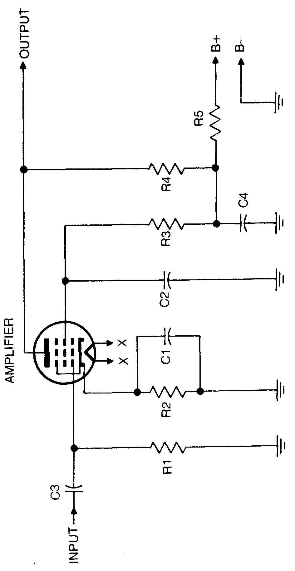
The circuit in FIG. 1 contains the component parts referred to in this section. Most troubles encountered are due to failure in circuits where DC is present. This means that the trouble can be located by voltage and resistance measurements.
Assume that the stage becomes inoperative. There must be certain DC potentials present for the stage to operate. The first step is to measure the voltage from the plate to ground. The voltmeter range switch must be set to the maximum voltage position because the voltage present is unknown. This precaution is necessary to prevent possible damage to the meter. If there is no voltage present, move the hot voltmeter prod to the point marked B+. If a voltage is indicated, an open circuit exists between that point and the plate of the tube. The screen-grid voltage will be below normal because the drop across screen dropping resistor R3 is greater than the normal drop. FIG. 1 shows that the plate voltage is applied through resistors R4 and R5. Move the meter hot test prod to the other side of R5. If the reading is zero, R5 is probably open, or C4 is shorted. A resistance check will verify this. If the reading is about normal, move the test prod to the plate again. A voltage reading on one side of R4 and none on the other means that R4 is probably open. A resistance check completes the test. Refer to Section 5 for checking resistors. A shorted C4 could cause the removal of plate voltage from the tube even though the B+ voltage is about normal. The screen-grid voltage also will be affected because it is taken from the same source as the plate voltage. A continuity check of C4 will then show either a dead short or a partial short to ground. In addition, R5 will overheat and many even char and smoke, because if C4 is shorted, R5 will be placed directly across the power supply.
Another cause for complete failure of the stage is the lack of screen-grid voltage when the plate voltage is nearly normal. A shorted screen-grid bypass capacitor C2 will reduce the voltage to zero. This can be checked by measuring the voltage from the screen grid to ground, and double-checked by making a continuity check between the same two points. Refer to Section 5 for checking capacitors. If the power is left on for a considerable length of time under these conditions, R3 and R5 will overheat and may even smoke, because they are connected directly across the power supply. This is a definite indication of a short circuit. Because the screen grid has more control on the plate current than the plate has, the plate current will go down; therefore, the plate voltage will be higher than normal.
Another test that can be made is the measurement of the cathode voltage across R2. If the voltage is higher than normal, R2 is probably open. Neither plate nor screen-grid current is flowing; therefore, the plate and screen-grid voltages will be higher than normal. The high-voltage reading is present across R2 because the high resistance of the meter completes the circuit across R2, creating a large voltage drop across the meter. The value of the voltage will depend on the type of voltmeter used. If R2 is shunted by an electrolytic capacitor, the circuit from cathode to ground will be completed by the leakage resistance of the capacitor. The cathode voltage would be only slightly higher than normal, regardless of the type of meter used to measure the voltage.
If the output of the amplifier is distorted, it is probably because the bias has decreased from the normal value. If the plate and screen-grid voltages are found to be lower than normal, bias capacitor C1 is probably shorted. This will produce distortion. Measure the bias between the grid and cathode. The voltmeter must be set to indicate a negative voltage. If C1 is shorted, the voltage will be zero. If the meter needle goes below zero, the grid is positive.
There is only one way the grid can become positive, in addition to gassy tube troubles, and that is for the coupling capacitor to develop a short circuit or leak, allowing the B+ on its other side to leak through to the grid. If C3 is checked with an ohmmeter, it might show an extremely high resistance, which means that it is not leaky. However, when power is applied to the circuit, including the preceding stage, the B+ appears between the ground and the input side of C3. As a rule, any capacitor having equal, or nearly equal, DC voltage from either side to ground should be suspected as being shorted.
If all voltage and resistance measurements are normal but the stage does not operate, coupling capacitor C3 may be open. The simplest, quickest and easiest method to check it is to bridge it with a good capacitor of the same capacitance and voltage rating. If C3 is open, bridging it will produce a signal in the output of the stage if a signal is applied to the input.
If the output is not as great as it should be and the voltage and resistance measurements are normal, it is possible that bypass capacitor C1 is open. If it is open, the decrease in output would be caused by degeneration. Signals that would normally be bypassed around the resistor by a good bypass capacitor will cause a signal voltage drop across the resistor. This voltage drop bucks the applied signal and effectively decreases the amplitude of the signal applied to the stage. As a result, the output also decreases. For example, assume that a 3-volt AC signal is applied between grid and ground. During the positive portion of the AC signal, the grid is 3 volts positive with respect to ground. This causes an increase in plate current through R2, and the developed voltage across it makes the grid negative with respect to ground, say 2 volts. Therefore, the grid is only 1 volt positive with respect to cathode. The 3-volt input signal is seen by the input of the tube as a 1-volt signal.
The most common troubles localized to audio stages are complete in operation, weakness, hum, motorboating, noise and distortion. The first step in locating the defective part within the stage should be a voltage measurement at each terminal of the tube socket. The manual for a radio set contains a tube-socket layout diagram showing the correct voltages at each tube-socket terminal, and also the resistance of the voltmeter that should be used. Compare the readings obtained from the defective unit with those on the diagram. A slight variation in readings is permissible, but if any great difference is noted, each component part of that circuit must be checked carefully for open or short circuits.
Resistance measurements should follow. To do this quickly, a few moments should be spent examining the circuit diagram to determine the approximate value of the resistance involved. In some circuits that use series and parallel networks, it would be quicker to isolate a portion of the circuit by unsoldering a connection and testing each section separately. Whenever low voltage is read, resistance measurements will determine the faulty component.
Trouble in an audio stage that is weak or completely inoperative can be located quickly by voltage and resistance measurements. This trouble is usually caused by a breakdown or change in the value of a component, and is indicated by incorrect voltage or resistance at one or more points of the circuit. Many times apart will change value only after the unit has been in operation for some time. Defective parts of this type can best be located by taking voltage measurements with a vacuum-tube voltmeter (VTVM). Comparing the readings obtained with those specified in the manual for the radio will then disclose the part across which a higher, or lower, than normal voltage is being develop
Hum is usually caused by loose shielding or DC circuit wiring accidentally placed close to AC circuits either during repairs or through vibration. A low-frequency hum generally originates from the filament wiring and can be corrected by repositioning grid and plate wires to place them outside the inductive field that exists around wiring in alternating current circuits. All filter capacitors should be carefully checked. An oscilloscope, or vacuum-tube volt meter with a capacitor in series with one of the test leads, connected between the tube-socket terminals and B— will indicate the presence of hum by a distorted sine-wave pattern, or a reading of the hum voltage.
Motorboating, or low-frequency oscillation, is usually caused by an open grid or cathode circuit. Open capacitors connected between the plate, cathode, or screen grid and ground may also cause motorboating.
When intermittent noise is noticeable in an audio amplifier, it may be attributed to a defective tube, the internal arcing of a component, or loose or high-resistance connections. All tubes, resistors, capacitors and soldered connections should be moved slightly and tapped gently with an insulated prod to locate loose elements in tubes or loose connections at any components.
Audio amplifiers using tubes in parallel or push-pull parallel arrangements usually employ a resistor in series with the plate of each tube to suppress parasitic oscillations. A change in value of this resistor will cause oscillation or distortion. Distortion localized to an audio stage in which the amplification is higher than normal indicates possible failure of components in the inverse-feedback circuit. Reference to the circuit diagram or the manual will show the proper values for components in this circuit, and resistance measurements will indicate the faulty part. In some amplifiers, degeneration is introduced by connecting a small capacitor between the plate of one tube and the grid of the tube in the preceding stage. This is done to reduce distortion originating within the stage at a slight sacrifice in gain.
Distortion in an audio stage is generally caused by improper bias or a defective audio coupling capacitor.
An oscilloscope is useful to determine quickly the sources of hum, noise and distortion in an audio amplifier. To do this, an audio signal generator is connected to the input of the audio amplifier, and the vertical plates of the oscilloscope are connected across the output circuit of the first stage. The audio generator is set at a low frequency, and the sweep-amplifier range control on the oscilloscope is adjusted to produce a stationary pattern on the screen of the cathode-ray tube. Should the pattern appear to be satisfactory, move the vertical-plate connections to the output of the second audio stage, where the sine wave may be observed again. Any distortion in the sine-wave pattern may be credited to the improper functioning of the audio circuits, and should be corrected before proceeding to successive stages.
ISOLATING TROUBLE IN I-F AMPLIFIERS
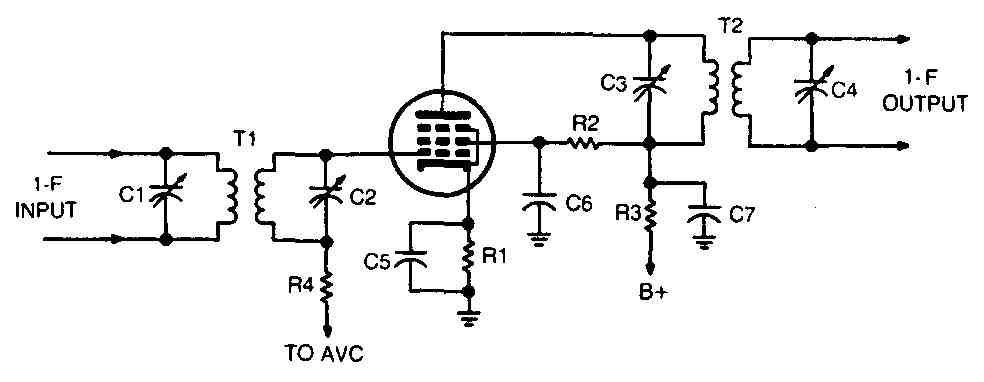
The method of isolating trouble in an IF amplifier is similar to that used for an audio amplifier. There will be shorted or open capacitors, open resistors and open inductors: These can be detected by making voltage and resistance measurements. An IF stage is shown in FIG. 2.
There is one exception to the above statement, and that is that the IF stage operates at a fixed higher frequency. The inductors must be turned to the proper frequency. Thus, if trimmers C1, C2, C3 and C4 are not set accurately, the output of the stage will be weak. Some radios have the windings of T1 and T2 tuned by varying the inductance with a powdered-iron slug.
Localizing trouble in an IF stage requires careful checking of very low resistance values, soldered connections, shielding and circuit components. The resistance of IF coils is usually very low, and when testing for shorted windings, the ohmmeter should be set on the lowest range and the measurements carefully made. Partially open or shorted coil windings can be quickly checked by aligning the stage and observing the output meter. If it is necessary to turn the trimmer adjustments all the way in or out to reach resonance, the coil is defective. Should the gain of the stage being tested be lower than that of other IF stages, careful resistance measurements of the windings and trimmer capacitors should be made.
The common troubles in IF stages are complete in operation, weakness, oscillation, distortion and intermittent operation.
An inoperative stage is usually due to the absence of voltage at one or more points, or it may result from a shorted or open circuit. The usual voltage and resistance measurements should indicate the defect quickly.
An IF stage in which the amplification is low is generally caused by improper voltages, partially open or shorted coil windings, or the need for alignment. A stage operating at low gain will give partial voltage and resistance readings, and extreme care should be taken to apply them logically to the apparent trouble.
Oscillation might be caused by loose shielding, a defective tube, or interstage coupling. To check the shielding, place the equipment in operation and move or tap the coil and tube shields by hand. If the frequency of the oscillation changes, the shielding should by cleaned and tightened where it contacts the chassis. All shielded wiring should be examined for cuts, worn spots and poor ground connections. Vacuum tubes can cause oscillation due to leakage between elements. Tube testers do not always indicate this condition, and the tube should be replaced if no part failure has been found. Interstage coupling may be the cause of oscillation, and it is usually the result of an open RF filter capacitor connected between DC circuits and the chassis. When these capacitors open the circuit, unwanted radio frequencies will be applied to tuned circuits and cause overloading of that circuit.
Distortion is usually caused by improper bias voltage or an open or shorted AVC filter capacitor. Potentials should be measured at the tube socket and followed by resistance measurements, if any differences exist. The grid-load resistor should be measured care fully. Close examination of all soldered connections and mounting hardware is necessary.
Intermittent operation of an IF stage is often difficult to locate because many components and circuit conditions can cause this trouble. Service and operation reports should be studied. Then the equipment should be placed in operation for a reasonable length of time to allow the trouble to show up without disturbing the circuits. Should the equipment operate correctly during this period, all wiring and components should be moved and tapped gently with an insulated prod. Before the trouble will show up, special operating checks might be necessary, such as placing the chassis in a refrigerator to chill it. If the stage cuts in or out rapidly, it generally indicates a loose connection in the wiring. Should this action be slow, it indicates a dielectric leakage or the opening and closing of a circuit by thermal action. Voltage and resistance measurements made when the receiver is operating correctly will not indicate the trouble. The application of test instruments to an intermittent circuit may create a very small voltage fluctuation that would cause the circuit to resume operation. Therefore, a very careful visual examination of electrical components and soldered and mechanical connections is important.
ISOLATING TROUBLE IN RF AMPLIFIERS
An RF amplifier is similar to an IF amplifier in practically all respects, except that its tuned circuits can be adjusted to resonate over a wide band of frequencies instead of one fixed frequency. Therefore, the troubleshooting method will also be similar.
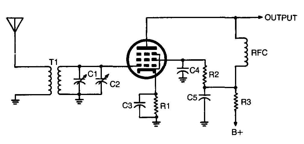
In the RF amplifier stage ( FIG. 3) choke RFC is the load. Other circuits may have a transformer winding or a resistor as a load. Regardless of the type of load, defects in them will cause similar symptoms.
The combination of the secondary of T1 and C1 and C2 must be tuned accurately to the incoming signal. Capacitor C2 is a trimmer which is set during alignment procedures. If its setting is disturbed, the sensitivity of the stage will be decreased and the signal output will be weak.
ISOLATING TROUBLE IN MIXER STAGES
The mixer combines the incoming signal and the local-oscillator signal to produce the difference frequency.
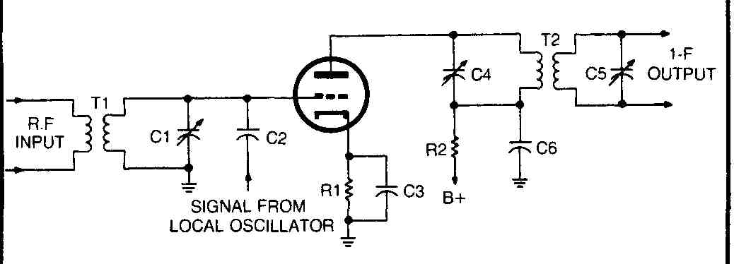
SIGNAL FROM LOCAL OSCILLATOR
Troubleshooting a mixer ( FIG. 4) is similar in most respects to troubleshooting an RF stage. In addition, it is important to check coupling capacitor C2. If it should open, there would be no oscillator signal fed to the mixer grid, and the intermediate frequency would not be produced. As in the RF amplifier, it is necessary to keep the adjustments that tune T1 and T2 set to the proper frequencies; otherwise, the output will be weak or not present. Transformer Ti is tuned to the signal frequency, and T2 is tuned to the difference between the incoming signal and the local oscillator frequency. FIG. 4 shows a triode mixer. A pentode mixer will include a screen grid and suppressor grid; otherwise, the operation will be the same as the triode mixer.
When troubles are localized to a mixer stage, the various frequencies and tube-socket voltages encountered must be considered. The function of a mixer stage is to beat the RF input signal against the signal of the oscillator stage to produce the IF signal. To obtain this result the tube voltages are critical. Therefore, the first step in localizing trouble within a mixer stage is a comparison of voltage measurements with those specified in charts for the particular radio.
The common troubles in a mixed stage are complete in operation, weakness, distortion, intermittent operation and noise.
In an inoperative stage, voltage measurements at the tube socket, followed by resistance measurements of the circuits in question, will usually disclose any open or shorted components.
A weak mixer stage will require checks for an inoperative stage plus the examination of wiring for open or grounded circuits. This can be done with an ohmmeter set on the lowest range.
A faulty vacuum tube or improper bias voltages can cause distortion. The tube should be changed if in doubt, regardless of the condition indicated by a tube tester. Defective components in the cathode and control-grid circuits cause improper bias voltage, and each capacitor and resistor should be individually checked to deter mine its condition. The circuit diagram of the equipment should be closely followed to avoid overlooking a component in the interconnecting grid, cathode and plate circuits.
An intermittent mixer stage should receive the same procedure as outlined for IF stages. The speed with which an intermittent condition can be corrected depends upon the resourcefulness of the repairman, as no set procedure will correct all intermittent troubles.
Noise that has been localized to a mixer stage might be due to low signal gain in the RF stages. Should a low-gain RF signal be impressed on the mixer stage, the noise frequencies may be amplified more than the signal. This condition should be determined, as it cannot be corrected in the mixer stage.
ISOLATING TROUBLE IN CONVERTER STAGES
A converter stage combines the elements of the oscillator and mixer tubes in one envelope. When making voltage and resistance measurements, the socket measurements are made at one socket instead of two.
In a pentagrid converter stage ( FIG. 5), the oscillator anode is also the mixer screen grid. Therefore, if the screen-grid voltage is absent, there is no voltage at the oscillator anode. The signals are mixed in the electron stream of the tube.
Anything that causes the oscillator to cease operating will prevent the intermediate frequency from being produced and fed to the primary of T3. The first test to make on the oscillator is to measure the bias. The bias must be measured across R1. If you use a voltmeter with less than 20,000 ohms-per-volt sensitivity, the volt meter could load the circuit to the extent that the oscillator will seem defective when it is operating normally. If there is very little or no bias present, the oscillator is not operating.
If trimmer C5 has been tampered with, the dial calibration on the receiver will be inaccurate and the signal of the wrong frequency will be fed to T3. If trimmer C2 is not set so as to produce maximum output, the output being fed to T3 will be weak.
ISOLATING TROUBLE IN DETECTOR STAGES
The detector demodulates or removes the intelligence from the carrier wave. Thus, when a signal contains voice modulation, the output from the detector will be speech.
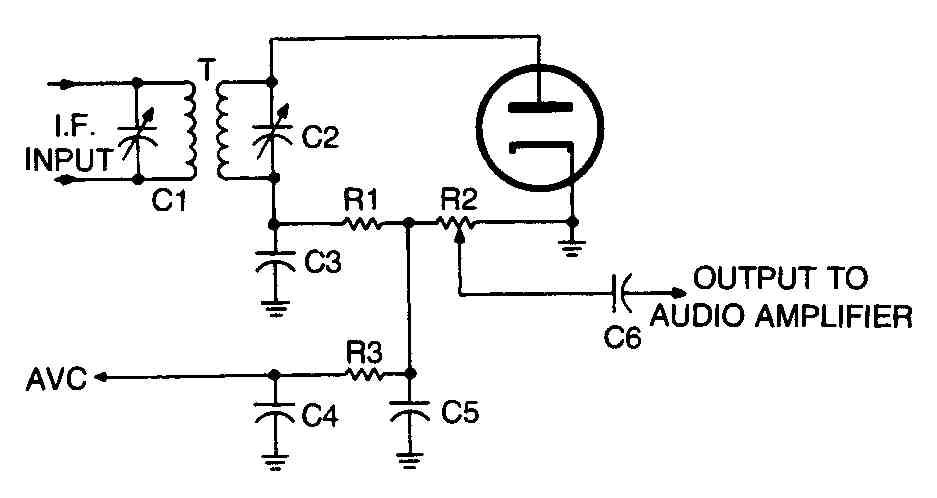
FIG. 6 shows an example of a diode detector. Because there is no high voltage present in this circuit, the chance of component breakdown is not very great. The primary and secondary windings of transformer T must be tuned to the proper frequency to produce maximum output. If R1 or R2 should open, there will be no output. An open circuit in C3 or C5 will reduce the output, but a short circuit in one of them would result in grounding the signal and no output.
The AVC voltage is developed across load resistor R2. If AVC filter resistor R3 opens, there will be no AVC voltage fed to the grids of the controlled stages, and the output will probably increase on strong signals. If AVC filter capacitor C4 short circuits, the AVC voltage will be reduced to zero, and the output may increase, depending on the value of the grid-return resistor in the controlled stages.
Old-time radios use different types of detectors, such as plate detectors, grid detectors and diode detectors. In plate detection the RF signal is amplified, then rectified. Grid detection does the reverse: it rectifies the RF input signal and amplifies the audio component. The diode detector offers no amplification of RF or AF signals. Many receivers use a twin diode detector to obtain a separate, rectified AVC voltage.
The most common troubles found in detector stages are complete in operation, weakness, distortion, noise and hum. The first step in determining a faulty component, when trouble has been localized to the detector stage is the comparison of all tube-socket voltages with those shown in the manual for the particular radio. When a defective circuit has been found, resistance measurements of the individual components within that circuit will isolate the defective part.
An operative detector stage is usually caused by an open or short circuit, which can be easily identified by systematic resistance measurements.
A weak detector stage generally indicates that a circuit is partially open or shorted. Each component requires a careful, individual check as the slightest change in value, over the tolerance limits, may reduce the gain of the stage.
Distortion in a detector stage can be caused by improper placement of circuit wiring, high-resistance connections, improper bias voltage and partially open or shorted components. In checking a detector stage for distortion, care should be taken to correct each trouble as it is located, because more than one condition may be the cause of this type of failure.
Noise originating in a detector stage usually indicates dielectric leakage or a loose connection. Ordinary meters will not always indicate trouble of this nature. Therefore, use an oscilloscope or vacuum-tube voltmeter as an indicating device. Connect the indicating device across various component parts of the stage and gently tap or move the parts. An intermittent pattern on the scope screen or fluctuating needle movement indicates the presence of noise in that circuit. If this condition exists when testing across a bypass capacitor, it will indicate it as defective.
Hum is generally caused by radiations from AC wiring, defective grid circuits, loose shielding, or defective filtering. Hum can be isolated to a part of circuit within the stage by using the same procedure as outlined earlier for the noise.
ISOLATING TROUBLE IN POWER SUPPLIES
A power supply delivers operating voltages to the various stages in receivers. The majority of troubles in a power supply occur in the high-voltage rectifier and filter sections.
The most widely used power supply is the full-wave type ( FIG. 7). The rectifiers are often contained in the envelope of one tube. Troubleshooting is done almost entirely by voltage and resistance measurements.
An open circuit in the primary or secondary winding of transformer T will result in no DC output. Also, if the windings are intact, an open in choke L1 or L2 will open the high-voltage circuit.
If filter capacitor C1 short circuits, the current through tubes V1 and V2 will be very high and will cause the high-voltage winding to smoke, or burn out the tubes. If output capacitor C2 short circuits there will be no DC output, but because of the resistance of the two chokes, the amount of current flowing will be less than if C1 short circuits.
The filter capacitors keep hum out of the operating circuits. Therefore, if either one should open, the output voltage will contain a ripple, and hum will result. There will be a large drop in the output voltage if C1 opens.
Bleeder R discharges the filter capacitors when the power is turned off. This is a safety measure. If the bleeder opens, the DC output point will be dangerous to touch because the capacitors will be fully charged. The bleeder also keeps a load on the output when the regular load is removed.
TROUBLESHOOTING IN POWER SUPPLIES
If the preliminary checks do not locate the trouble, it will be necessary to test the individual components of the unit.
Most troubles in power supplies are caused by a breakdown of parts in the filter circuits. One method of testing filter circuits for defective parts is by checking the resistance of the input and output circuits. By comparing the figures with those specified in the manual, or using a practical application of Ohm’s Law for series-parallel circuits, the defective part can be determined. An advantage of this method of testing is that the power supply is inoperative during the test; therefore, no damage can result to any part from excessive current flow should a short circuit exist. Most AC power supplies have small bypass capacitors connected between each side of the input supply line and ground to prevent high-frequency noises from entering the equipment through the power lines. As the DC resistance of the primary winding of the power transformer is comparatively low, the condition of these capacitors cannot be determined by a resistance check across the primary winding. If melted paraffin or compound surrounds the capacitors, they should be removed and checked on a capacitor tester. After checking the power-supply input circuit for continuity and correct resistance, place the ohmmeter test prods across the input to the filter circuit. A reading will be obtained of the equivalent resistance of a complex network, composed of the resistance of the choke, in series with the parallel resistance of the second capacitor leakage and bleeder resistor. As the leakage resistance of normal electrolytic capacitors is relatively high, with respect to that of the bleeder, it will not greatly affect measurements for practical purposes. The ohmmeter will really read the resistance of the filter choke, in series with the resistance of the bleeder resistor.
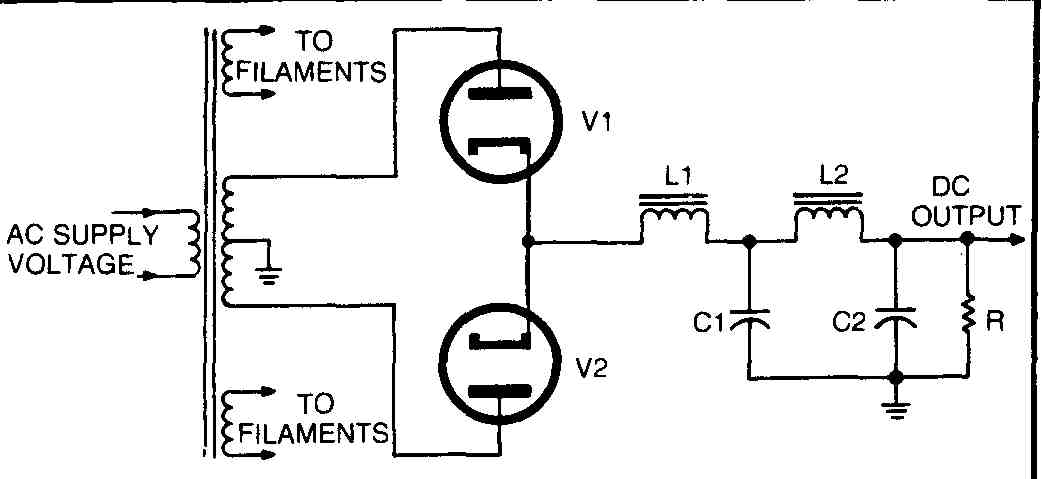
Fig. 7. Full-wave rectifier power supply.
If the ohmmeter prods are connected across the output terminals of the filter circuit, a reading will be made of the equivalent resistance of the bleeder resistor, shunted by the leakage resistance of the second capacitor, and also shunted by the resistance of the choke, in series with the first capacitor. In this case the ohmmeter will read, for practical purposes, the resistance of the bleeder resistor only. Thus the resistance of the input circuit to the filter is higher than that of the output circuit by the value of the choke.
If the choke was short-circuited, the readings at both input and output would be identical. If the choke was open-circuited, the input readings would be very high (leakage resistance of the first capacitor) and the output reading would remain practically the same. If either capacitor was open-circuited, both readings would remain about the same. If the first capacitor was short-circuited, the input resistance would below, and the output reading would be the value of the bleeder resistor, in parallel with the choke. If the second capacitor was short-circuited, the input reading would be the value of the choke, and the output resistance would be very low. Likewise, other possible troubles can be found by similar analysis.
Common troubles in filter chokes are open or partially open coils, internal shorts across the terminals of the coils, leaks or partial leaks to the frame of the inductance and shorted turns.
An open choke will cause no voltage output from the power supply, and a partially open choke coil causes low-voltage output. High hum, or ripple, in the output voltage will result if the coil develops a short across its terminals. Sometimes the filter capacitors develop an internal short from one positive lead to the other. This will effectively short out the choke and cause a hum. Capacitors that are used to resonate the choke should also be suspected when this type of trouble is encountered. Some filter circuits use a capacitor across the filter choke to resonate it to the frequency of the hum voltage. Since a parallel-resonant circuit offers very high impedance to its resonant frequency, very little hum voltage will be apparent at the output of the filter. If a large percentage of the coil turns short out, similar trouble may be expected. Leaks or shorts to the choke frame, or iron core, will cause low or no voltage output, and are similar in effect to a shorted or leaky filter capacitor.
If the capacity of the first capacitor is low, the output voltage of the filter will be lower than normal and will have considerable ripple voltage in it. Lack of sufficient capacity in the second filter capacitor will cause the filter circuit to act in a similar manner as to the hum or ripple voltage, but the DC output voltage will be only slightly affected. Sometimes insufficient capacity will cause motorboating, degeneration, or regeneration. If regeneration occurs, the equipment might break into oscillation, whereas degeneration would cause lower amplification. This may cause distortion, if some frequencies are amplified more than others.
Summing up these facts, low amplification, instability and high hum level can be caused by the second filter having insufficient capacity, or having decreased incapacity. These are common troubles when electrolytics dry out or lose electrolyte through evaporation or decomposition, which results in a decrease in capacity and the troubles discussed above. When a capacitor decreases incapacity, it is equivalent to a good capacitor that is partially open-circuited. Shorted filter capacitors are the cause of very low or no voltage output from the filter. Partially shorted filter capacitors cause the voltage to be lower than normal, and the hum level to be high.
CAUTION:
The voltage stored in filter capacitors does not always leak off when the power supply is disconnected from the supply line. To avoid shock, short circuit all capacitors with a low value resistor before handling components of power supply.
ISOLATING TROUBLE IN OSCILLATOR STAGES
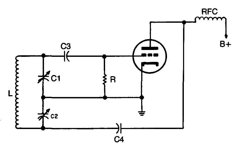
The circuit in FIG. 8 is that of a widely used oscillator. It is used to assist in troubleshooting oscillators. The parts referred to in the text are marked on the diagram.
In general, the method for troubleshooting an oscillator is the same as that used for an amplifier, because an oscillator is basically an amplifier that has provisions for positive feedback.
Connect the test prods of an electronic multimeter across grid-leak resistor R ( FIG. 8). The grid will be several volts negative with respect to the cathode if the stage is oscillating. If it is not oscillating, there will be little or no voltage present. Do not use a low-resistance meter; the circuit will be loaded down and the stage will cease oscillating if it had been in operating condition.
If the above test shows that the oscillator is not operating, voltage checks must be made. This is a shunt-fed circuit, and nothing is in the B+ line to burn out except the RF choke. If the plate voltage is normal, make resistance checks on the other components.
Capacitor C4 connects the plate of the tube to the lower end of indicator L. If C4 opens, oscillation would probably cease because the feedback circuit will be broken.
Trouble localized to an RF oscillator stage is frequently found to be one of three types: failure to oscillate, weak oscillations, or oscillation at the wrong frequency.
Failure to oscillate results in no output from the receiver or transmitter. The lack of oscillation usually can be traced to an open or shorted coupling between the plate and grid circuit of the tube, an open or shorted grid resistor, an open cathode resistor, a shorted trimmer or tuning capacitor, or a faulty tube. You’ll find some tubes that will test satisfactorily on the tube tester, yet when placed in the circuit will fail to oscillate. The first step in isolating trouble in an oscillator stage is to check the socket voltages against the voltage chart for the receiver. Any material deviation from the given standards indicates trouble in that portion of the circuit where incorrect voltage occurs. Localization of the faulty component can be accomplished quickly by continuity and resistance checks fail to disclose any part failures.
Weak oscillation produces a considerable loss of sensitivity in a receiver, with an attendant drop in overall performance. In a transmitter, the output will be extremely low. The fault generally lies in an open or partially shorted coupling between the grid and plate circuits of the tube. Where the coupling is capacitive, a leaky capacitor will decrease the amplitude of oscillation. A partially shorted or open coupling coil will have a similar effect. Check coupling capacitors for leaks, and coils for continuity. Low plate voltage will cause weak oscillation. In converter tubes, low screen voltage or lack of screen voltage produces a like result.
Oscillation at the wrong frequency is characterized by either no response from the receiver or reception of only a portion of the coverage of the receiver at either the lower or upper end of the band, depending upon which side of the fundamental frequency the oscillator is designed to operate. This condition can be caused by a change in the value of components, a partially shorted tank coil or tuning capacitor, an incorrectly aligned oscillator, or a faulty tube, the latter being most evident at the higher frequencies, where a change in the interelectrode capacitance of the tube elements can cause a frequency shift. Check components for value and test for continuity and shorts. A check to determine whether the oscillator is operating correctly can be made by setting the dial of the receiver at a point near the low-frequency end of the dial and feeding a modulated signal of the same frequency from a signal generator into the receiver. Then check the frequency of the oscillator with a frequency meter. The frequency of oscillation should be either the sum or difference of the IF and RF input signals, depending upon whether the oscillator is designed to operate on the high or low side. In some receivers, the oscillator operates on the high side in the lower bands and on the low side in the higher bands.
LOCALIZING TROUBLE IN AUTOMATIC VOLUME CONTROL CIRCUITS
Many different types of AVC circuits are used in old-time radio sets to vary automatically the grid bias on RF and IF amplifier tubes, thereby maintaining a constant output signal over a predetermined range of RF input-signal amplitude variation. To correct trouble localized to AVC circuits, first carefully examine the schematic diagram for the particular unit to determine the type of circuit used, and where control voltages can be measured to quickly localize the defective part.
The most common troubles encountered in AVC circuits are complete in operation and partial operation of the circuit.
Complete in operation usually has one of two effects on the performance of a receiver, depending upon the nature of the trouble. One condition is extremely high sensitivity and background noise caused by shorted wiring or capacitors. This condition can be quickly located by resistance measurements at various points in the circuit. The other condition is low sensitivity caused by an open resistor or a defective AVC rectifier tube. The first step in localizing trouble of this nature is to determine whether the AVC rectifier tube is functioning. You can do this by measuring the voltage across the AVC load resistor with a vacuum-tube voltmeter. A lack of voltage at this point indicates a defective tube or coupling capacitor. If voltage is present across the AVC load resistor, voltage and resistance measurements made across successive parts of the AVC network will reveal a defective component.
Partial operation of the AVC stage usually results in a distorted output on strong signals and is generally due to a shorted AVC filter capacitor. The defective circuit can be located by connecting a vacuum-tube voltmeter between the control grid of each tube in the AVC network and ground, beginning with the AVC rectifier tube. The absence of voltage on a certain stage indicates an open, shorted, or grounded component, and the careful checking of each part with an ohmmeter will disclose the part failure.
