The Williamson 40/40, Power Amplifier--Return of an improved favorite after a decade
by REG WILLIAMSON, Contributing Editor
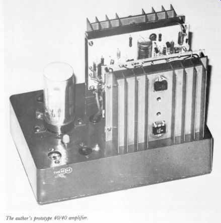
The author's prototype 40/40 amplifier.
IF I MIGHT SUGGEST a further comparison to your readers, the Twin Twenty schematic shows the age of the amplifier. While this type of amplifier was considered quite good in 1969 when it was designed, it can hardly be considered State-of-the-Art any longer."' So opined a critic of one of my creations back in 1970. My goodness, was it really that long ago? I must confess to a twinge of surprise that this, my very first design published in the newly-hatched Audio Amateur (TAA 1/70, p.4), is now a decade old. At the time, I never did regard it as State-of-the-Art (whatever that may mean) since by 1969 most of the serious problems surrounding the design of transistor audio amplifiers had been identified and were well on the way to being solved. The principal factors usually preoccupying the circuit designer were those of the cost and com promise in meeting the design specification; and so it was for me in the case of the 20/20. No revolutionary ideas, no innovations; in short, it followed concepts firmly proved by others before me.
It worked well and presented no problems for the competent home constructor, the latter prerequisite imposing certain constraints frequently overlooked by some of my contemporaries specializing in ' 'do-it-yourself' projects. Despite the gentle brick thrown at it by one of my readers, of all the projects I have ever prepared for the home constructor this one still brings in the most letters of comment and query. The kit of parts is still available-yet to the best of my knowledge Old Colony have never declared a policy of going into the antique business! So clearly it met then and continues to meet the needs of many of TAA's readers.
This is not to ignore the fact that it is 10 years old and in the context of today's standards it does fall short in certain areas. In power, at a 20 watt rating per channel and with speaker efficiencies steadily drifting downwards, its muscles are a bit puny. This factor persuaded me to take a further critical look at the design, especially after my good friend Alan Watling announced his intention of going ''four channel' with the 20/20 at the heart of the system. And, of course, it was Alan who in his article last year (''Pandora's Box,"" TAA, 1/78, p. 4) revealed the existence of the updated 20/20 in his elegant four-channel set-up.
The inevitable letters followed; so, with a little arm twisting from our Editor, here it is for you to consider as your next constructional project.
As before, Old Colony will probably offer a kit of parts soon after this article appears. My design philosophy has remained unchanged. Components should always be reasonably accessible to the constructor, avoiding any exotica. The project should need no fiddly setting up.
Above all, the builder should have some leeway in component selection: in my experience home builders always write to ask if so-and-so's make of transistor can be used instead of that suggested by the designer. In this respect, the new version is even more indulgent than the old one.
Since owners of the '69 version may wish to update, some of the original parts may be used again-but not, I regret, the etched board; that must be replaced. [See Figs. 3 and 4.]
--------------
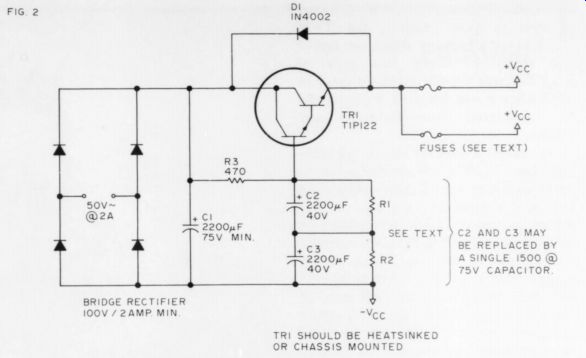
Fig. 2. The power supply schematic. The Darlington semiconductor acts as a capacitance multiplier. The two resistors equalizing the two output capacitors should be between 470k and 1-Meg, but reasonably well matched, at least to + 5%.
-----------
PARTS LIST: POWER SUPPLY
TR, Texas TIP 122 D, 1N4002 R; 2 1M -ohm C, 2200uF, not less than 70V 2200uF not less than 40V.
4700 Bridge rectifier, (silicon) 200piv, 2A or better Transformer, 118/50V, not less than 100V RRM @2A.
--------
IS IT BETTER? Now you'll be asking, is the performance improved? To be honest, I suspect the improvement is less audible than measurable. The inherent distortions introduced by the amplifier were already much lower than those contributed by the rest of the transmission chain, particularly in the program source, anyway. For example, the THD is nearly all low order, predominantly second harmonic (the ''nice'' sort); measured, it was never greater than 0.05% from 40Hz up to 8kHz. At 15kHz it was still less than 0.1% with a resistive load and much less with a typical speaker system.
On the matter of power rating, here I can claim some enhancement over the original design, which, incidentally, was for a nominal 16 ohm loading. These days the norm is more likely to be 8 ohms. So taking advantage of a wider range of semiconductors, plus some changes in the power supply, I am ready to accept Alan Watling's suggestion that the updated design may legitimately be called the 40/40. So be it.
PHILOSOPHY MATTERS
Before discussing the design changes in detail, let me-as the Irish say-trail my coat a little by airing a few personal observations. As a practicing design engineer with over 30 years experience, I think far too much is being made today of newly discovered aberrations in audio amplifiers, which seem to appear with monotonous regularity. If nothing else, I'm trying to introduce some sense of proportion into the arguments which seem to go on ad infinitum. Let me mention, for example, TIM and SID about which a great deal of smoke is currently being generated in respected quarters.
In the first place, there has never been any great difficulty in producing test signals that audio amplifiers will mangle to death or malformed in some way. Consistently overlooked is their relevance to real program material and the parameters required in the program chain for this material to be transmitted without significant deterioration. In connection with this contentious subject alone, I commend to TAA readers one of the important series of articles on the whole subject of audio amplifier distortion written for Wireless World by my friend Peter Baxandall. The one I have in mind appeared in the January, 1978 issue.
I know of no more down-to-earth, realistic engineer than Peter. In this superb essay, he carefully dissects most.
of the pro-SID/TID arguments; subjects them to critical analysis with complementary tests; and reaches some startling conclusions undermining many cherished beliefs concerning amplifier performance criteria that are being carefully nurtured in certain quarters.
Yet Peter Baxandall is no willful iconoclast; his arguments are almost un challengeable. Let me mention one conclusion he reached: a power amplifier capable of full power output on sine waves up to 2.2kHz, without suffering from slew rate distortion and with sufficient freedom from ordinary non-linear distortion, will subjectively be perfectly satisfactory. No, that is not a misprint-I did say 2.2kHz. Surprised? I need hardly add that even a 10-year old design such as the 20/20 would have no difficulty meeting that sort of requirement.
This is not to deny, of course, that any design engineer should always take measures to avoid feeding into the system program material that the individual elements are incapable of handling without degradation; and in the system itself, any economically possible improvements should be introduced, even though they may seem of academic value. In the case of the new 40/40, I have included those I have felt worthwhile.
POWER SUPPLY ISSUES
So to the circuit itself. I like to begin with the power arrangements. Yes, I'm well aware that these days it is customary to power with balanced feeds and the technique certainly has virtues.
The major one is economic: it does save a few parts and is inherently superior on the point of regularity. Other claims for it are suspect. For example, consider the suggestion that low frequency performance is improved because of so-called " direct coupling.'' I have yet to meet a hifi enthusiast who can convince me this method of power supply provides true direct coupling. One has only to trace out the signal path at any point in any audio amplifier to end up going through a capacitive element.
The technique has one major potential disadvantage: I speak with some feeling after seeing the divider network in an expensive speaker disappear in smoke after an output transistor failed in a 'direct coupled'' amplifier. Protection measures are mandatory and fusing alone is hardly adequate. The dc ''sit"' point at the speaker terminals must also be very low, since only a few millivolts offset across a low Z speaker will cause a significant current to flow through the system with possible performance degradation. So I still feel a single ended and possibly regulated power supply is preferable if the user wishes; the one still on offer from Old Colony for the old 20/20 is suitable. [See Jim Boak's regulated Supplies in Issue 1, 1980. - Ed]
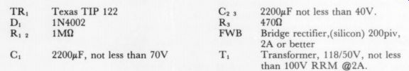
Fig. 1. Schematic diagram of the 40/40 amp. Parts in the dashed line boxes are mounted off the board, although if TI's TIP35/316C pair a used, they may he soldered directly to the board and attached through two holes in the board to a 0.75 "piece of aluminum angle which may then be attached to a heat sink, thus also mounting the board itself Note: all capacitor voltage ratings are absolute minimums, higher ratings may be used.
---------------
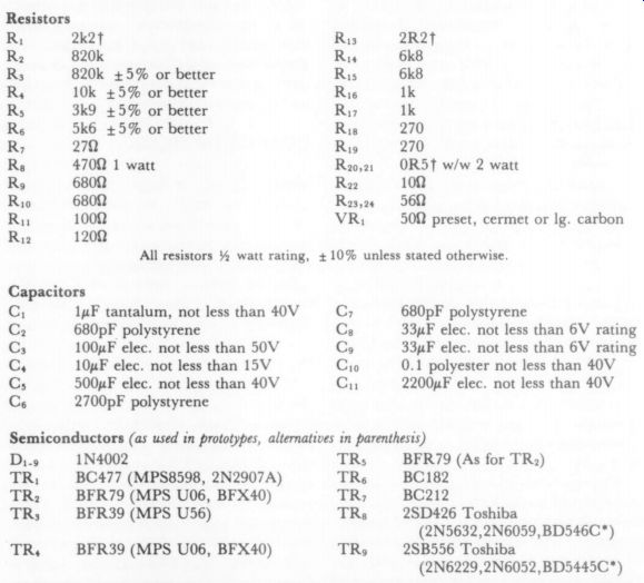
PARTS LIST: AMPLIFIER ONE CHANNEL
Resistors 2k2t 820k 820k +5% or better 10k +5% or better 3k9 +5% or better 5k6 +5% or better 27 ohm 4700 1 watt 6800 6800 1009 1200 All resistors 2 watt rating, 2R2t 6k8 6k8 1k 1k 270 270 OR5T w/w 2 watt 10 ohm 560 5 0-ohm preset, cermet or lg. carbon
+ 10% unless stated otherwise
Capacitors C, 1uF tantalum, not less than 40V C, 680pF polystyrene
> 100uF elec. not less than 50V 10uF elec. not less than 15V 500uF elec. not less than 40V 2700pF polystyrene 680pF polystyrene 33uF elec. not less than 6V rating 33uF elec. not less than 6V rating
0.1 polyester not less than 40V 2200uF elec. not less than 40V
Semiconductors (as used in prototypes, alternatives in parenthesis) Dis 1N4002 TR, BC477 (MPS8598, 2N2907A) TR, BFR79 (MPS U06, BFX40) TRs BFR39 (MPS U56) TR, BFR39 (MPS U06, BFX40) TR; TR TR, TRs TR, BFR79 (As for TR) BC182 BC212 2SD426 Toshiba (2N5632,2N6059,BD546C*) 2SB556 Toshiba (2N6229,2N6052,BD5445C*)
Sundry parts such as heatsinks, two fuse holders and fuses (two @ 1.5A slo-blo for nominal 8 ohm loading), circuit boards, etc.
*Indicates possible plastic devices for TRg and TR; I have not tried them.
1 2R2 =2.2 ohm ; also 2k-ohm =2.2k2; 0R5 =0.5 ohm.
---------------------
In conventional unregulated supplies the smoothing element in the circuit is a passive first order RC filter. The resistive element, very low, is the series component of the transformer secondary plus the forward resistance of the rectifiers. Since ideally the time constant (R x C) should be as long as practicable, the C element is customarily very high and may be as large as 10,000uF. Even so, this means a time constant that may be insufficiently long to avoid hum ripples appearing on peak waveforms at the amplifier's output near its maximum rating. One cannot increase the R component artificially since this degrades supply regulation.
A NEW APPROACH
For those who would like to try something new, I suggest an alternative to a more expensive regulated supply:
one with an active filter. I have yet to see this technique tried elsewhere and since it has proven workable in both my prototype and Alan Watling's superb four channel system, you may care to try it.
One may interpret how it works in more than one way. It may be a device to increase the R component by a large degree, or the C component. But most important, the regulation is not materially affected. It requires, simply, introducing an unusual circuit con figuration into the power line. The time constant of the power filter is now, near enough, the product of the R and C in the filter, which works out in my design to about 0.5 second. The capacitor need not be a high ripple type; in fact, because of size considerations, I used two in series (with high value resistors across to equalize the polarizing potential). To permit enough current at maximum power levels to pass through the Darlington power transistor, the R element should be no larger, but the C element may be bigger if you wish. I use one filter element for a stereo pair but, again, you may use one per amplifier which improves regulation.
The first virtue of this technique, apart from cost saving, is ripple will now not exist on peaks of high power. The second is the power supply eases on gently, which is a good thing in many ways, notwithstanding avoiding the nasty plops one gets as the various capacitive elements in the amplifiers charge up. The peak power rating is also improved and moves closer to the ideal one normally achieves with a more costly regulated supply.
Readers may be a little puzzled on seeing the photograph (Fig. 5) and may speculate where the power transformer has gone. Here's an end to the mystery: it's in the base, mounted in the case with the remainder of the power section. I permitted myself the indulgent luxury of using a toroidal type. It isn't essential, of course, and at the time ofwriting I'm not at all sure whether they are easily obtainable in the USA from normal parts sources. I'm sure with their characteristic ingenuity Old Colony will locate some if at all possible-but don't regard a toroid as a sine qua non.
AMPLIFIER CIRCUITRY
Now let's have a look at the amplifier, beginning with the input section. No great changes here: a single p-n-p transistor, moderately high h, and with a V... not less than 60V operating in the common emitter mode. Base bias is via a star configuration whose junction is bootstrapped into the main feedback loop to eliminate the shunting effect of the bias network across the signal path.
The bias potential also determines the basic 'sit point'' at the output stage and is 2 VV... Needless to say, the resistors in this network should be of close tolerance and not worse than 5%.
If you have the old 20/20 schematic to hand, you'll notice too we are sneaking a bit of the voltage drop across this net work via two diodes in the + V, line.
More on that later. One extra addition, a simple first order low pass filter at the input, inhibits supersonic components in the program from getting into the amplifier. The turnover point is a function of the source Z, so it should not be greater than 5k-ohm .
Most of the voltage gain takes place in TRs, an n-p-n transistor. It should again be of moderately high h, with a Ve not less than 80V and preferably higher. Plenty of suitable devices exist and the Py, should always be not less than 750mW. This stage also operates in the common emitter mode, but we have a fundamental change compared with the old 20/20 design in the use of a static constant current load. For minimum non-linearity in the transfer characteristic for the output stage, drive it from a constant current source. I achieved this in the original 20/20 by a dynamic bootstrapping circuit from the output to the resistive load of the predriver stage. On reflection, the alter native I'm now proposing is much better since it carries with it other advantages such as less critical bias setting. (An early criticism of my original choice was quite correct and I failed to appreciate it at the time.) The constant current load is a p-n-p transistor of moderate hy, a V,,, not less than 80V, and P,,, not less than 750mW (actually, the recommended complement to the predriver device will do nicely). The base bias for this transistor is from the constant voltage across the two diodes I referred to earlier in the +V, line; so since the base requires 0.6V to turn the transistor ''on'' and we have 1.2V, then the transistor will re quire 0.6V at the emitter before current limiting begins. In this case the current will be held constant at 0.6 / 120, where 120 ohm is the value of the emitter resistor. So simple arithmetic yields a current of dm/A. Agreed? Sorry if this has offended all the pundits who naturally knew this, didn't you? But I am surprised at the number of enthusiasts who fail to appreciate how this simple and often-used circuit technique works.
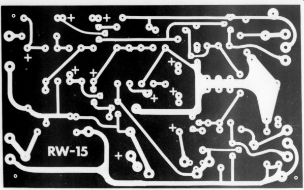
Fig. 4. Negative pattern, full size of the 40/40 amplifier circuit board.
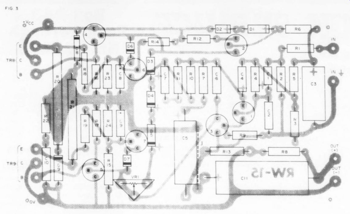
Fig. 3. Stuffing guide for the RW15 circuit board. Two sets of holes
are supplied for VRI1. The larger trio for an ordinary large preset.
The smaller set are for a vertical cermet type. Do not use a small carbon
preset here as it is likely to fail.
OUTPUT DEVICES
Now to the output stage which is virtual ly unaltered except for the introduction of some protection circuitry. Leaving that for the moment, we still have two compound, complementary collector pairs; and as before, the base/emitter inputs consist of four diodes in series which have to be biased ''on." This forward bias is provided by the network of three diodes plus a small 5 0-ohm trimmer potentiometer as part of the pre-driver load. The setting of this p-meter which should be either the larger conventional sort or a cermet type, determines the quiescent current in the output stage which, as I said earlier, is not especially critical. [Note that two sets of holes are provided on the board for this trimmer: large for a vertical type, small Jor a cermet type. -Ed.]
If you have a distortion factor meter available, then set bias just above the value at which the last vestiges of crossover distortion disappear, as viewed on an oscilloscope. This will normally be for a typical quiescent current (total for the whole amplifier one channel) of about 50m/A. I suggest, by the way, that this setting-up procedure, I preferred, be at a 1 watt level into 7.5(2, at a frequency of 1kHz.
As for protection ckts I have added to the amplifiers, the particular type used must be designed with some care and will be no substitute for generously rated devices in the output stage. It must, in other words, be regarded as a lifejacket to be brought in to use when all else fails! That which I have adopted is designed to protect the output devices and their compound drivers from excessive loading under over-volt as well as overcurrent conditions and, in restricted circumstances, from the both where the loading is highly reactive-as indeed, it is likely to be with real loads. Dg and Ds protect the output devices against the possibility, with reactive loads again, of the center rail voltage rising above or below that standing at the collector of each of the output transistors. (Yes, it can really happen.) Clamp transistors TR4 and TR7 limit the current drive to the output stage when biased on, and this condition will obtain when current at the sampling point-the output transistor emitters-exceeds a certain value, or when the voltage across the devices also exceeds a certain value. To allow again for the probably simultaneous occurrence of both under reactive loading conditions, I have added a short time constant to the simultaneous occurrence of network providing the ''bias on'' potential for the clamping transistors. Other protection measures are orthodox, the inclusion of fuses in the power lines being one obvious measure. These should be of the ''slo-blo'' type.
BUILDING TIPS
A few final words about construction technique. First, don't be stingy about heatsinks. Second, observe carefully the important matter of grounding. I've provided an independent output ground return on the board-use it and no other. The other ground and 0V rails of each channel should common together at two points only. One is at the -V, terminal of C, in the power supply (and use heavy gauge conductor throughout for all power wiring including the one jumper on the circuit board which should be at least #20). The other point is at the inputs, where the common point may also be grounded to the chassis. Even so, you will observe we still have a ground loop between the two channels by virtue of this wiring technique, and unless we take certain precautions heavy currents could circulate through the small signal stages giving rise, possibly, to a significant increase in distortion at peak power levels. This, by way of answer to many silent questions, is the function of Rs, the 2.2) resistor in the middle of the 0V line between the driver and output stages. This resistor should never get warm; and if it does, look for a wiring error somewhere.
As for using other than recommended transistors and diodes: as I intimated earlier, this updated design is rather more tolerant than the original back in '69. Alan, for example, is happily get ting away with MJ2955 and its n-p-n complement the ubiquitous 2N3055; but I have reason to think his custom built speaker system presents a "'kindly"' load to the 40/40, and with four channels working he probably never runs anywhere near the rated output of the individual amplifiers. Back in '69 we didn't have a wide choice, and deliberately going for high-rated devices in the output stage meant also a sharp increase in cost for the home builder.
This is not quite so bad now. With a wider range to choose from and with normal market forces as a consequence keeping the prices down, the home builder can afford to select high-rated devices; and with the odd load conditions presented by some speaker systems today this is a sensible move. The alter native list I have given is by no means exhaustive but merely represents those I have actually tried in the circuit.
CORRUPTION LEVELS
Now for a few comments about performance. Those who look for a catalog of numbers before feeling confidence in the design will be sadly disappointed. If I say the amplifier is rated at 40 watts per channel into 7.59, then at this level with a 550mV sinusoidal input signal of in significant harmonic content over a frequency range from 50Hz to 10kHz, the output signal sampled across the resistive load will measure 17.4 volts and the harmonic corruption introduced by the amplifier will also be in significant-+for those who do like a number, certainly less than 0.1% THD and predominantly second order. In other words, distortion's a tiny fraction of that inherent in the program source or contributed by the rest of the pro gram chain. No new square wave oscillograms, either. If our Editor still has those published for the original 20/20 (TAA, 1/70, p. 4), then these will suffice because there is no change.
I hope I needn't emphasize that this assessment of how the updated design performs is the worst possible. Real loads, for example, are not purely resistive and a speaker system with a nominal 8ohm loading is likely to deviate upward from this value. Unless ypu spend your time playing tapes of sustained organ chords, the actual power available on most program-type signals will be substantially higher than the rated figure, and will certainly be tar higher for both sustained and program- type signals if a regulated power supply is used.
Before ending, and anticipating the question that is bound to arise: am I proposing to also update the preamplifier? Frankly, I don't know certainly some small improvements are possible. Let's just see how you get on with the new 40/40.
----
Also see:
Test Report: Listening tests of the PAT-5/WJ-1A, by Laurence L. Greenhill, M.D.