AN ELECTRONIC SPEED CONTROL FOR BELT-DRIVE TURNTABLES
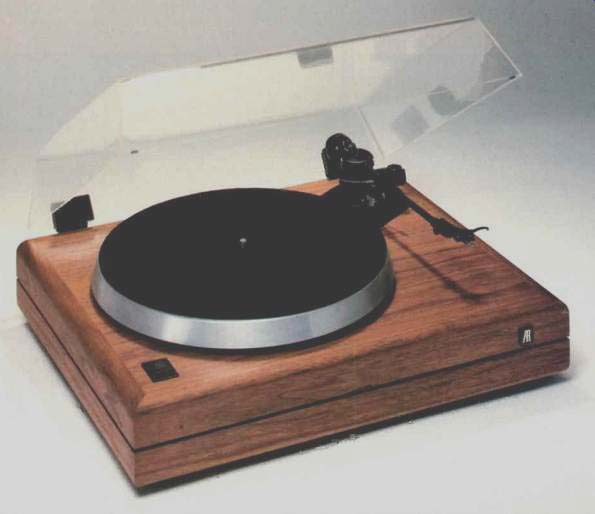
THIS PROJECT HAS AN INTERESTING history. While attending the October 1984 AES convention in New York City, I mentioned to TAA Editor Ed Dell that I hoped to develop a device that would provide electronic speed control for belt-driven turntables. I thought it would be a natural follow-up to my turntable project, which appeared in here in 3/1985.
Several months later, readers Dewey Peace and Michael Keely of San Antonio, Texas, sent Mr. Dell a copy of an article from the July 1983 issue of Wireless World titled Frequency Control of Turntable Motors' and written by Peter A. Stockwell of Dunedin, New Zealand. Readers Peace and Kelly suggested that TAA adapt the project to US line voltage and frequency. Mr. Dell asked me to take on the assignment, and thus Mr. Stockwell's article formed the basis for my speed control.
Project Rationale
As most readers undoubtedly know, most high-quality belt-driven turn tables employ a synchronous motor. The speed of synchronous motors is determined by the line frequency (60Hz in the US and Canada). Synchronous motors are insensitive to changes in line voltage and will operate over a range of approximately 90 to 135V RMS. Since the line voltage often deviates considerably from the nominal 117V AC, this is a desirable characteristic.
A synchronous motor's rotation is smoothest if it is fed a clean, undistorted 60Hz sine wave. This can have a positive effect on sound reproduction, as Linn has demonstrated with its Valhalla modification. The waveform supplied by power companies often contains harmonics and noise, making it a less than desirable power source for a high-quality turntable. I have measured total harmonic distortion (THD) on my power line of anywhere from 1 to 5 percent, depending on the time of day. In my opinion, 1% is an acceptable figure, but 5 percent is not. I am sure many power companies allow distortion and noise to exceed that figure.
The device described here provides a sine wave that is lower in noise and distortion (less than 0.5 percent) than the wave provided by most power companies.
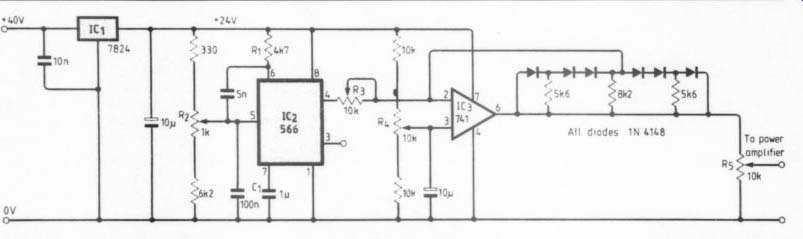
FIGURE 1: Peter Stockwell described this oscillator circuit in his Wireless
World article. IC2 generates a triangle wave, which IC3 and the diode-resistor
network shape into a sine wave of about 5 percent distortion. (Reprinted,
with permission, from Wireless World. Copyright 1983 Business Press International.)
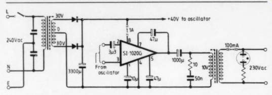
FIGURE 2: Dr. Stockwell's power supply and power amplifier are based
on the Sanken S1-1020G module. (Reprinted, with permission, from Wireless
World. Copyright 1983 Business Press International.)
The 60Hz frequency is very closely regulated where I live, but in some locations it is not. This results in shifts in turntable speed as the line frequency changes. To listeners who are sensitive to pitch changes (as I am), even a 1Hz change is slightly audible. This device provides stable, drift-free frequency control of the turntable.
Many listeners find variable pitch useful on turntables, but this feature is absent on belt-driven turntables using synchronous motors. In my case, I own many long-playing reissues of 78 rpm recordings that have been transferred to LP at the wrong speeds.
(Many so-called “78s ” were recorded at other speeds. For a more detailed discussion of this, see ‘A Preamp for Vintage 78s' in TAA 1/85.) Some musicians “play along ” with their recordings-and often find it necessary to “tune ” their turntables to match their instruments. The oscillator used in this project can be switched from a fixed 60Hz frequency to variable frequency, allowing the user to raise or lower the pitch by an interval of approximately a major third. In addition, the frequency can be switched to provide 45 rpm and even 78 rpm, without changing pulleys or moving the belt. I will discuss potential problems with running a synchronous motor this far away from its design frequency later in the article.
Implementation
Figures 1 and 2 show Peter Stockwell's circuit. Figure 1 is his oscillator, based on a 566 function generator chip (IC2). The 566 has a triangle wave output, which is shaped into an approximation of a sine wave by IC3 and the diode/resistor feedback matrix. The oscillator's output is then amplified to about 10V by a Sanken S1-1020G power amp module, shown in Fig. 2. The 10V is then stepped up to line voltage (230V AC in New Zealand and Europe) by means of a filament transformer used backward. A common power supply operates the amplifier and oscillator circuitry, although the oscillator has its own regulation (IC1).
I believed that I could improve two aspects of Mr. Stockwell's design.
First, the distortion level of his oscillator is too high to provide motor rotation that is as smooth as possible.
The sample circuit I built has a THD of 5 percent. Second, he used only one ten-turn potentiometer to select all speeds from below 33.333 to above 78 rpm. This makes speed changes inconvenient. The power amplifier circuit is fine, but the Sanken module is not readily available, so I had to find an alternative.
I felt that a Wein bridge oscillator, which has an inherently low-distortion output and is extremely stable in terms of frequency, would be ideal.
Unfortunately, this oscillator is very difficult to stabilize in terms of amplitude. I built a prototype of Walt Jung's FET-stabilized Wein bridge oscillator, which is shown in his book I.C. Op Amps for Audio Applications (p. 180). Unfortunately, any attempt to vary the frequency, which requires adjusting two resistance elements simultaneously, made the oscillator very unstable. Mr. Stock well mentioned having similar experiences with Wein bridge oscillators.
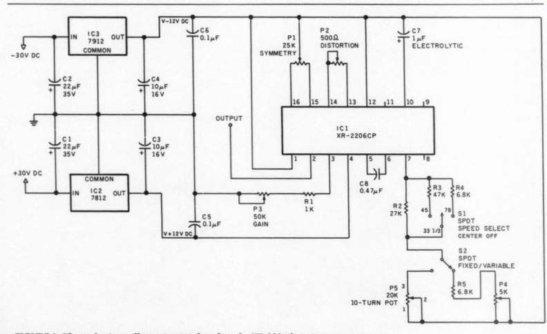
FIGURE 3: The author's oscillator circuit is based on the XR-2206 function
generator chip. P1 and P2 trim the distortion to less than 0.5 percent.
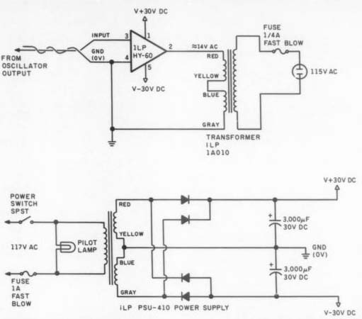
FIGURE 4: Power amplification is provided by an ILP HY-60 module, which
is operated by the PSU-410 power supply.
The solution proved to be an XR 2206 monolithic function generator chip, manufactured by Exar Integrated Systems of Sunnyvale, California. It has a sine-wave output, and the distortion can be trimmed to less than 0.5 percent (mine measured 0.38 percent). It is extremely stable, with a frequency drift of only 20 parts per million (ppm) per degree Centigrade. This is the lowest drift of any function generator chip I have found.
The Intersil ICL-8038 drift is 50 ppm, and the National Semiconductor 566 is 100 ppm.
My oscillator circuit is shown in Fig. 3. The frequency is determined by C8 and the resistance from pin 7 to the V-supply. It is given by the formula f= 1/RC. The frequencies required for 33 1/3, 45 and 78 rpm are 60Hz, 81Hz and 140Hz, respectively. Two SPDT (single-pole, double throw) miniature toggle switches are used for speed selection. S1 selects the nominal speed, while S2 changes from fixed-speed to variable-speed operation.
With the fixed/variable switch in the fixed position, the P4 trimpot trims the 33 1/3 speed to exactly 60Hz.
This is a one-time adjustment. In the variable position, P5, a 20k ten-turn Bourns pot, adjusts the oscillator frequency. A turns counter facilitates adjustments. Trimpots P1 and P2 ad just distortion to less than 0.5 percent, and P3 adjusts the output level.
The power amplifier supply pro vides unregulated power. The 7812 and 7912 IC regulators, with appropriate input and output filtering, ...
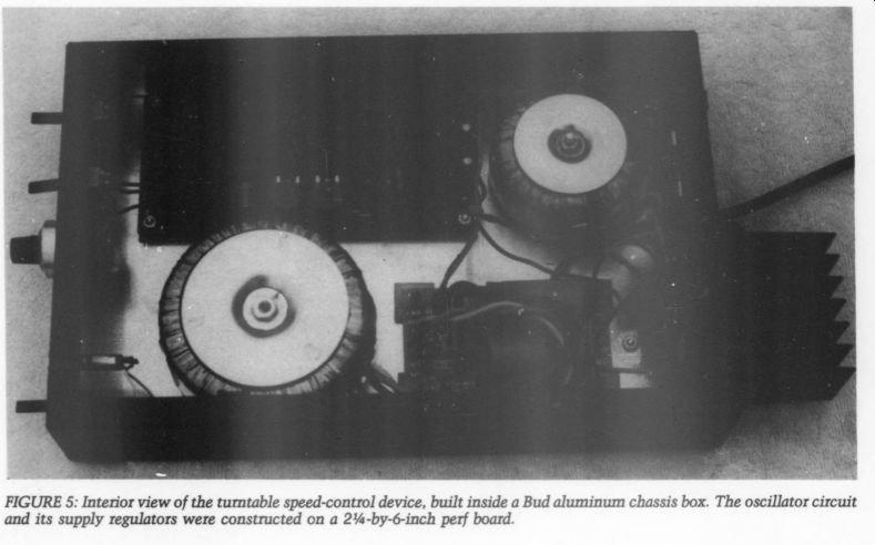
Fig. 5
... supply the oscillator chip with + 12V of regulated DC. C5 and C6 bypass the supply lines close to the oscillator chip.
The power amplifier and power supply circuits are shown in Fig. 4.
The ILP line of power amplifier modules and toroidal transformers, distributed by Gladstone Electronics (see supplier list), was the solution to the amplification requirements. To pro vide enough output voltage to drive a filament transformer (backward), a 30W audio amplifier was necessary.
I used an ILP HY-60, a mono 30W module. The HY-60's output drives an ILP 1A010 toroidal transformer, connected backward, so the 12V secondary is used as the primary.
You should not substitute other devices for the 1A010 toroidal transformer. The high efficiency of toroidal transformers provides an easy load for the amplifier module to drive. The amount of current required to magnetize the core of this transformer is only a few milliamps.
A conventional filament transformer, such as Radio Shack ’s #273-1511, will draw much more current, just to magnetize the transformer core. This is undesirable.
Power for the HY-60 module is provided by an ILP PSU-410 power supply, which includes a 4A027 toroidal power transformer plus a PCB-410 circuit board containing the rectifier diodes and filter capacitors.
As mentioned previously, the PSU 410 supply also provides unregulated DC to the oscillator regulators.
Construction Hints
Step-by-step construction details are not necessary because of the straight forward nature of the circuit, but a few suggestions might be helpful.
Figures 5, 6 and 7 show the interior, front and back, respectively, of the speed-control device. I used a Bud AC-407 aluminum chassis and a BPA-1594 'bottom' plate. What Bud calls the 'bottom' plate is actually used as the “top” plate in my layout.
As shown in Fig. 5, I constructed the oscillator circuitry on a 23.5-by-6-inch piece of perf board. All components shown in Fig. 3 are mounted on the perf board except S1, S2 and P5. They are mounted on the front panel, as shown in Fig. 6. The two 0.1uF supply bypass capacitors should be mounted as close to the chip as possible.
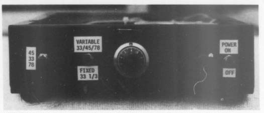
FIGURE 6: Front view of the device, showing speed selector switches,
the counting dial for the Bourns 20k pot, and the power switch and pilot
lamp.
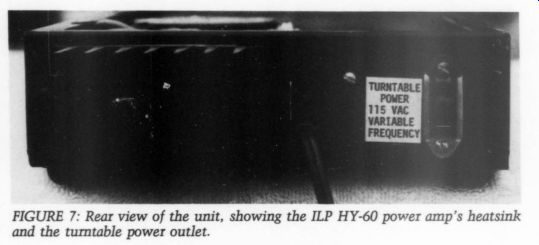
FIGURE 7. Rear view of unit.
.. .the rear of the chassis to accommodate the HY-60 module and the power outlet, as shown in Figs. 5 and 6. The PCB-410 power supply circuit board mounts directly behind the HY-60 module, and the 4A027 power transformer is mounted between the board and the front panel. Note that the fuse clips on the PCB-410 boards are not used. Be sure to observe polarity when connecting the HY-60 module to the + 30V rails, as reversed polarity will destroy the HY-60.
Under no circumstances should the + 30V rails be fused. ILP warns that the failure of a single fuse could damage the HY-60. The power switch and pilot lamp are mounted on the front panel, as shown in Fig. 6.
Figure 5 also shows the relative locations of the oscillator board and the 1A010 step-up transformer. Note that the 1A010 has two 6V windings, which connect in series to form a 12V “primary. ” Color coding for both toroidal transformers is shown in Fig. 4. The oscillator perf board should be mounted with 1/4-inch plastic spacers. It would also be a good idea to put a 2 3/4-by-6-inch cardboard insulator against the chassis, under the board and spacers. My board has a number of bare-wire jumpers on the bottom, and the cardboard ensures that they will not accidentally touch the chassis.
A single chassis ground lug should be mounted between the HY-60 module and the PCB-410 circuit board.
All grounds shown in Figs. 3 and 4 should connect to this point. A twisted pair can be used to connect the oscillator output to the HY-60 in put. The ground wire connects only at the chassis reference point, near the HY-60 input, and floats at the other end.
When the counting dial is mounted on the Bourns ten-turn pot, the pot should be fully counterclockwise.
The counter should then be mounted with the indicators showing 0.0. Fully clockwise rotation will give a 10.0 indication.
Adjustments
You will need an AC voltmeter and an oscilloscope to adjust the completed speed control. A harmonic distortion analyzer is helpful but not absolutely necessary. Any power line grounds on the test equipment should float by means of a three-pin to two-pin adapter. All trimpots except P3 (gain) should be set to the center of their rotation. P3 should be set to minimum resistance, which corresponds to the lowest output.
The speed switches (S1 and S2) should be set to 33.333 and should be in the “fixed” position.
Temporarily disconnect the oscillator output from the HY-60 in put. Connect an oscilloscope and, optionally, a harmonic distortion analyzer to the oscillator output. Ground reference for the test equipment connections is the chassis ground lug.
Turn on the unit. A waveform resembling a sine wave (it might be somewhat triangular) should appear on the oscilloscope. Adjust the P3 gain pot for an oscillator output of about 1.5V peak-to-peak on the scope. If you are using a distortion analyzer, adjust P2 for the lowest harmonic distortion. Then adjust P1 to reduce the distortion further. This should result in 0.5 percent or less distortion. P2 is the sine-shaping adjustment, and P1 adjusts waveform symmetry.
If you do not have a distortion analyzer, you can observe the effect of the adjustments on the oscilloscope. Adjust P2, then P1, for the smoothest, most symmetrical waveform. You might have to repeat the two adjustments to obtain the lowest distortion, regardless of which method you use.
Turn off the unit and reconnect the oscillator output to the HY-60 input.
Connect an AC voltmeter to the , turntable power outlet. Plug the turntable into this outlet. It is essential that the turntable to be used is connected to the device at this time. The turntable's power consumption should not exceed 100mA (11.5W).
Connect the oscilloscope to the output of the HY-60. Turn on the speed-control device and the turn table. Adjust the oscillator gain to produce 115V AC RMS at the turn table power outlet. Repeat this adjustment after 15 minutes of operation, as the XR-2206's output decreases very slightly with warm-up. The waveform observed on the oscilloscope should show no signs of clip ping. Now adjust trimpot P4 to achieve a precise 33 1/3 rpm fixed speed. The easiest way to do this is to monitor your turntable's speed with a strobe disk, observed under a 60Hz fluorescent or strong incandescent light source. Adjust P4 to achieve a stationary pattern on the strobe. A more precise means of adjustment is to monitor the HY-60 module's output on a frequency counter. In most locations, the line frequency is regulated closely enough to make this unnecessary. If your counter is inexpensive, with only + 1Hz resolution, the strobe will probably be more accurate.
The speed-control device is de signed to operate modern belt-driven turntables employing low-current, synchronous motors. Among these turntables are the AR, Linn Sondek and Thorens models, along with my turntable described in TAA 3/85. It will deliver nearly 100mA of current to the motor at 115V AC (11.5W).
The AR motor draws only 1.5W, and Merrill's replacement motor consumes only 3W.
If your turntable draws 100mA, you might have to reduce the output voltage to 110V to avoid waveform clipping. If you plan to operate a turn table that exceeds 100mA, you must use a larger power amplifier module.
I recommend the ILP HY-128, a 60W module, with the PSU-420 power supply. If you run the oscillator off the PSU-420 supply, you should put small heatsinks on IC2 and IC3. Such turntables are rare, and it is doubtful that outdated turntables, such as the Rek-O-Kut B-12, which draws 200mA, would benefit sonically from this device, as their inherent noise levels and speed accuracy leave much to be desired by today's standards.
-----------------
PARTS LIST
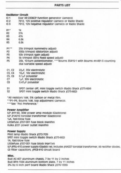
Oscillator Circuit
IC-1 IC-2 IC-3
R1, R2 R3 R4 RS
1K 27k 47k 6.8k 6.8k
P1°* P2 P3 Pa PS 25k trimpot (symmetry adjust) 5000 trimpot (distortion adjust) 50k trimpot (gain adjust) 5k trimpot (33.333 fixed speed adjust) dial (variable speed adjust)
C1, C2 C3, Ca Cs, C6 c7 C8
22yF, 35V electrolytic 10 uF, 16V electrolytic
0.1 uF polyester 1uF, 30V electrolytic
0.47uF polyester Exar XR-2206CP function generator (Jameco) 7812, 12V positive regulator Jameco or Radio Shack) 7912, 12V negative regulator Jameco or Radio Shack) 20k, 10-turn potentiometer, Bourns 3541S-1 with Bourns #H-491-3 counting
$1 SPDT center off, mini toggle switch (Radio Shack #275-664) S2
*All resistors 1/4W, 5 % carbon or metal film.
SPDT mini toggle switch (Radio Shack §275-662)
**P1-P4, Bourns ¼ W, top adjustment (Jameco).
See “Pot Preference. ” Power Amplifier ILP #HY-60, 30W power amp module (Gladstone) ILP #1A010 toroidal transformer (Gladstone) 1/2A, fast-blow fuse Littlefuse #357-001 fuse block (Hanifin) Kulka #221 power outlet (Hanifin) Power Supply Pilot lamp (Radio Shack §272-703) SPST mini toggle switch (Radio Shack #275-662) 1A, fast-blow fuse Littlefuse #357-001 fuse block (Han'7n) ILP #PSU-410 power supply (Gladstone), includes s4A027 toroidal transformer, (4) rectifier diodes, (2) filter capacitors, #PCB-410 circuit board
Misc.
Bud AC-407 aluminum chassis, 7 by 11 by 2 inches Bud BPA-1594 aluminum bottom plate, 7 by 11 inches 2.5 by 6 inch perf board (Radio Shack §#276-1395)
--------------------
--------------------
Pot Preferences
Gary Galo has a very strong preference for his favorite means of adjusting speed with this device. If you build one, the ten-turn pot and dial may be your choice as well. Unfortunately, the Bourns units he uses are expensive ($30 each) and difficult to obtain. An alternative ten-turn, 20k pot with a mating counting dial is available from Allied Electronics (see Sources). The ETI #MW22-10 ten-turn, 20k pot is Allied #522-2044 ($5.85), and the ETI #MG-22 dial is Allied #522-2855 ($6.75).
There are other ways to control your unit's speed. The simplest method is to use two pots (20k and 1k) in series (Fig. S-1). Calibrate the circuit by set ting the 1k pot at its marked midpoint, then measure the turntable speed with a neon bulb and a stroboscopic disk, marking the dial of the 20k pot for 33 1/3, 45 and 78 rpm speeds. The 1k device will function as a vernier, while the main pot will set the approximate speed. You may replace the 20k pot with a three-position, single-pole shorting switch with four fixed 4W resistors whose value can be derived by measuring the resistance of the 20k pot, temporarily mounted and calibrated in the unit (Fig. S-2). Measure the increments between speed positions, then replace the pot with the four fixed resistors.
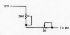
FIGURE -1: Using two potentiometers in series is a simple way to control a unit's speed.
A 12-position, single-pole shorting (make before break) switch with twelve 1.56k, 1/4W resistors used with a 2k pot for vernier adjustment (Fig. §-3) will accomplish the speed-control function in another less costly manner.- Ed.
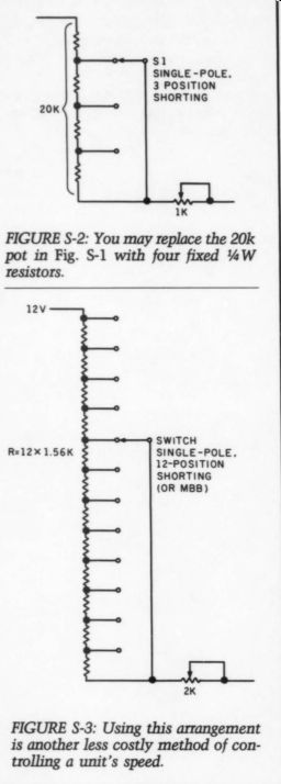
FIGURE S-2: You may replace the 20k pot in Fig. S-1 with four fixed 0.25 W resistors.
FIGURE S-3: Using this arrangement is another less costly method of con trolling a unit's speed.
---------------------------------
I have operated the B-12 with the HY-60 module, but the voltage must be reduced to 100V to avoid wave form clipping. Even at this reduced voltage, the HY-60 runs very warm, since it must supply 1.4A to the transformer. I do not think that this is a desirable long-term situation.
The speed-control device will not operate direct-drive turntables or any other turntable that already has built in electronic speed control. Some Thorens models, such as the TD-126 series, fall into this category. It will not work with Linn turntables employing the Valhalla modification either. If you think the variable-speed options provided by this device would be useful on your Linn table, my ad vice would be to have your Linn dealer remove the Valhalla modification and return the turntable to nor mal 60Hz operation. Undoubtedly, your Linn dealer will list a dozen or more reasons why you should not do this. My device and the Valhalla modification both provide the motor with a clean, stable, low-distortion waveform, but the Valhalla mod offers no switchable speeds or variable pitch options.
Operation
In normal use, you should operate the speed control with the speed switches set to “fixed ” and 33 1/3. With S2 set to the “variable” position, an indication of 5.0 on the counting dial represents a speed very close to 33.33 rpm. Increasing the count (turning the dial clockwise) increases the speed, while decreasing the count slows down the turntable. If you switch the speed to 45 or 78 rpm, you must adjust P5 slightly to achieve the exact turntable speed, which means that S2 must be in the “variable ” position. I optimized the “fixed” position for 33.333 rpm operation. Doing otherwise would have involved extra trimpots, which I felt were unnecessary.
If you are playing 78s, the variable pitch option is a necessity. Again, please refer to my TAA 3/85 article for details.
The 78 rpm speed might present problems with some turntables.
Many synchronous motors do not operate very efficiently when the operating frequency deviates considerably from the design frequency.
For instance, the AR turntable motor “clogs ” noticeably if it is operated at this speed with the belt removed.
With the platter and belt installed, platter rotation is smooth, due to the flywheel effect of the heavy platter.
The turntable will not start at this speed, however. The best way to achieve 78 rpm speed on an AR turn table is to begin at 33 1/3, switch to 45, then switch to 78. The AR motor is rather noisy when operated at 78 rpm.
Another problem concerns the weight of 78 rpm recordings. On my belt-driven turntable using three spring suspension, the excessive weight of the records will bottom the suspension, causing the platter to scrape against the top plate. You could, of course, adjust the suspension for 78 rpm disks, but it would ...
-------------
SUPPLIERS
Allied Electronics: Call (800) 228-6705 for the distribution center nearest you.
Gladstone Electronics Inc. 1585 Kenmore Ave. Buffalo, NY 14217
Hanifin Electronics Corp. PO Box 188 Bridgeport, PA 19405
Jameco Electronics, 1355 Shoreway Road, Belmont, CA 94002
---------
... no longer be correct for long-playing records.
In sum, I think the 78 rpm speed will be of limited use with many belt driven turntables, but I encourage builders of this device to experiment and to report their results. The 45 rpm speed works well on an AR turntable, although start-up is a bit slow.
An additional benefit of operating your turntable with this device is a noticeable sonic improvement. Specifically, I noticed an improvement in midrange and high-frequency detail and smoothness. The sonic differences may vary from rather subtle to quite obvious, depending on how much noise and distortion are present on your power lines.
My HY-60 power module stays very cool, even after several hours of continuous operation. It runs some what warmer with turntables that have greater power consumption than the AR, but the oscillator has no noticeable warm-up frequency drift and has not needed readjustment after two months of operation.
Toroidal transformers radiate a very low hum field. To be sure your cartridge does not pick up any trans former hum, you should not place the speed-control unit beside the turntable next to the tonearm. In stead, you should put it on the side opposite the arm. Placement is not critical with my cartridge (a Grace F9E ruby), but some cartridges might be more sensitive, particularly moving coils.
I hope you find this to be a useful and reliable project. I would like to acknowledge the assistance of Ken Koster of Gladstone Electronics for his help in selecting the power module and transformers for this project. I would also like to thank Peter Stockwell for granting permission to reproduce the circuit described in his Wireless World article. Photographs were taken by the author and were developed and printed by Paul Steinberg.
ABOUT THE AUTHOR: Gary Galo is an Audio Engineer at the Crane School of Music, SUNY, Potsdam, where he also teaches courses in sound recording and audio technology. For five summers he has been on the faculty of the Saratoga-Potsdam Choral Institute, teaching high fidelity, opera and recording history. Mr. Galo has a B.M. in Music Education and an M.A. in Music History and Literature, SUNY, Potsdam. His personal record collection has over 2000 LPs and 2500 78s, mostly operatic and symphonic music. He continues to remain active in music, having recently conducted excerpts from Schoenberg's Gurrelieder on the Crane Faculty Artist Series. He is a member of the AES, the College Music Society and the Association for Recorded Sound Collections.
-------------------------
Also see:
Heybrook TT2 Turntable and Tonearm (Nov. 1984)
AR SYSTEM DRIVES NEW TURNTABLE
PREEMINENT PHONO PREAMP, By John H. Roberts