A BROADBAND SIGNAL SNIFFER
A SOME POINT in the course of troubleshooting, repair, kit building or component modification, the serious audio builder will run in to a situation where his or her test equipment might not have the sensitivity to measure a low-level wave form. For example, phono head-amp and preamp stages, as well as tuner radio-frequency (RF) and intermediate-frequency (IF) stages, usually carry low-level signals that might be difficult to visualize or measure with a scope or counter lacking sufficient sensitivity. This is particularly true with the low-budget test gear likely to be found on a home-brew test bench. Frequency counters, for example, might require signal levels of 50mV or more to register accurately, and some older or no-frills oscilloscopes might require similar signal levels to stabilize their triggering circuits.
What do you do when you want to view the waveform or measure the frequency of a signal whose ampli tude is only a millivolt or two? You could take out a second mortgage and refurbish your test bench with mil spec test gear, but a somewhat more cost-effective approach might be a low-level broadband preamp that you can assemble easily for about $16.
The BAX-1 Broadband Amplifier
The heart of this instrument preamp is the BAX-1 broadband amplifier kit from the International Crystal Manufacturing Company (ICM), located at 10 North Lee, Oklahoma City, OK 73102. ICM manufactures crystals for use in RF applications, as well as component video gear for professional and consumer applications. ICM also offers a variety of other inexpensive kits for applications such as RF oscillators, amps, power amps and mixers. All these kits, including the BAX-1, are available for less than $10.
The specifications of the BAX-1 are listed on page xx. Figure 1 is a close up of my constructed version of the unit. The kit comes with composition resistors and 2.5uF coupling capacitors. Being somewhat of a purist, I substituted carbon film resistors and high-value coupling capacitors.
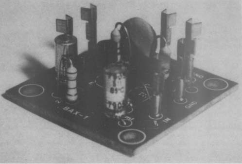
FIGURE 1: Close-up of the BAX-1 preamp board.
The entire amplifier is mounted on a tiny 1.5-inch-square etched and drilled phenolic board that comes complete with its own spacers and #4 mounting hardware. A four-page manual contains the circuit schematic, specifications, construction tips and diagrams of suggested ap plications. All things considered, this preamp kit is a useful little package at a bargain price.
Test-Bench Packaging
To make effective use of the BAX-1, you must equip the stuffed circuit board with a protective housing and RF shield, as well as a DC power source. It is also convenient to have some sort of input-signal attenuator if you wish to use the unit with line level voltages. Figure 2 is the schematic of the complete signal sniffer unit. I bought the case at a local Radio Shack store. The remain ing components-banana jacks, phono jacks, switches, battery clips, wire and the input attenuator-were all junkbox items.
You have considerable flexibility in choosing the input and output jacks.
You might want to omit the banana jacks and install only the RCA types.
You can also use BNC jacks if you plan to use the BAX-1 mainly in RF circuits. Likewise, you might want to eliminate the external DC switch and jacks if you are going to run the unit just with batteries. You should also consider the value of the input signal attenuator. Too large a value might cause circuit instability at high frequencies, while a very low value might place an undesirable load on the test circuit. In my unit, I used a value of 5k, which has worked well for the past two years.
Figures 3 and 4 show the outside of the sniffer, while Fig. 5 shows details of component placement in side the case.
Over the past couple of years, I have used the sniffer many times on my test bench. Current drain from the batteries is very low, so they last a long time. I also noticed that the sniffer unit has a remarkably high input-overload capability, which makes it useful as a general-purpose signal booster. The trade-off in this application is a marked reduction in gain as the input signal level is increased. Even with audio sine-wave signal-input levels of ZVpp, however, the unit exhibits a gain factor of two or three before visible clipping occurs.
The unit's compact size makes it easy to stash on a crowded test bench, while its portability makes it useful for remote applications. In sum, this is a useful test-bench accessory that is easy to assemble and costs what today amounts to pocket change.
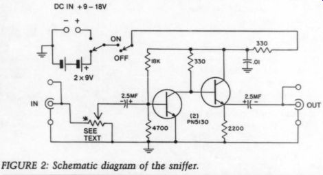
FIGURE 2: Schematic diagram of the sniffer.
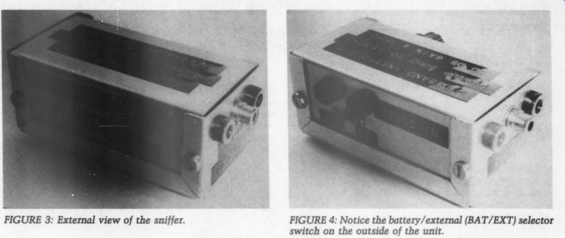
Fig. 3. FIGURE 4: Notice the battery/external (BAT/EXT) selector switch on the outside of the unit.
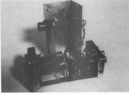
FIGURE 5: Interior view of the sniffer.
--------------

Specifications
DC Power Required
Frequency Range
Gain at 1MHz (0.001V in) at 150MHz
Response Ref. 1-MHz
Operational Impedance Noise
Maximum Input Level
Output at Maximum Input at 1 MHz
Size Mounting
9 to 18V DC at 10mA max.
20Hz to 150MHz 30db 6dB
Down 6dB to 50Hz
+ 3dB 100Hz to 10MHz
Down 15dB at 100MHz
Down 24dB at 150MHz 50 to 500 ohm
Less than 10uV RF across 50 ohm ; audio less than 0.005V
0.01V AC 50 ohm , 0.1V 5009, 0.5V 1.5 by 1.5 by 1 inches
Four holes with spacers
------------------
By Benjamin L. Poehland.
----
Also see: