BY L.B. DALZELL
CONSIDER THIS. Supper is over and you decide to listen to some good music. You take your dessert and refreshment to the side table by your comfortable chair that is right in the ‘sweet spot ’ for the best listening. You turn on the reading lamp at the side table where you put your snack, and the music system comes on. Now you put a disk in the CD player on the other side of your chair-the player that you have improved immensely courtesy of the POOGE-4 articles in TAA.! Later, when you decide to retire, you turn off the reading lamp and the equipment goes off.
This ‘mini-drama’ is about constructing a sensing device that will control the AC power to your sound system. It began when the owner of a quality hi-fi shop in nearby San Diego called and asked whether I could see a way to solve a problem. He had an Exotic unit, a combined tuner/preamp that was great but had no switched outlet, making it necessary to turn on each piece individually, which did not make the built-in arrangement he was planning as comprehensive as he would have liked.
I investigated the Exotic unit and developed a power cord that allows measurement of AC current. Use of this disclosed that the unit has an idle current to keep the circuits warmed up, and a much higher operating current.
I designed and tested a circuit for the unit that functioned well and has operated flawlessly for more than two ...
----------
ABOUT THE AUTHOR
Mr. Dalzell retired in 1985 after a long career with the Bell System, where he did mostly engineering and circuit design work. He ’s been interested in audio since the early fifties, and has had several articles published, starting as early as 1959 in Audio magazine. He is spending some of his retirement designing audio related devices.
----------------
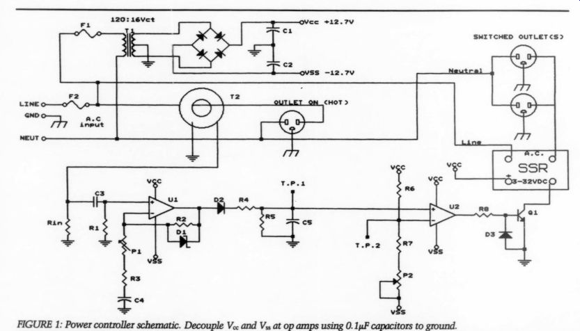
FIGURE 1: Power controller schematic. Decouple V.. and Vis at op amps using
0.1uF capacitors to ground.
...years. This fits into a connecting wall outlet device that the Exotic unit can be plugged into. The circuit differentiates the unit ’s different AC current levels and controls a couple of outlets to turn on the amplifier, player, and so on.
Subsequently I built and installed a number of the devices to control sound systems, or systems behind big projection television units. Anything-reading lamps, preamps, you name it- can be plugged into my devices for the control.
Figure 1 shows the circuit. T2 is a current transformer, shown in more de tail in Fig. 2. The line wire from the AC input is routed through the open center hole of T2, and from there to the ‘on’ ( ‘HOT ’) outlet. When AC current flows to the load from ‘on, ’ an AC voltage is induced into the toroid winding that we will use.
The next requirement is a circuit to sense this induced voltage, or its absence, and control a switching device to turn the switched outlets on and off.
Op amps are used, hence a small power supply is included. One wire from the current transformer is grounded and the other is terminated by (more on this later). The AC signal is then capacitor coupled to U1.
R1 places a reference ground on the noninverting input of U1. The output of U1 is fed back to the inverting in put via the network R2, P1, R3, and C4.
P1 controls the gain of U1. D1 is a 10V zener diode that limits the positive swing of U1 to 10V and the negative swing to about -0.6V. (This arrangement is common in the literature.) R3 limits the gain of U1. The signal is then rectified by D2, limited by R4 and charges C5 to a level we will discuss later. R5 is a high resistance shunt to bleed C5 ’s charge for turnoff.
U2 is another op amp. Its non-inverting input is tied to C5, R5. The inverting input is tied to a divider made up of R6, R7 and P2. R6 and R7 are equal value to place a virtual ground on the inverting input of U2, which establishes a switching point. P2 controls the positive voltage at the inverting in put to establish a desired switching level. Note that U2 ha no feedback, hence it acts as a comparator. As soon as the noninverting input of U2 is more positive than the reference inverting input, the op-amp output will swing to a level near the positive rail (V_cc). When the capacitor voltage at Cb and the non-inverting input of U2 go below the reference inverting input, the op amp will quickly swing to a level near the negative rail (V_ss).
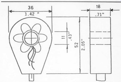
FIGURE 2: The transformer is encapsulated in a nylon housing and has a pigtail
type connector lead for its output signal.
------------------
PARTS LIST
Capacitors
C1, C2 470uF/25V or larger
C3 2.2 uF/50V film ca 100uF/16V 0.1 uF/50V film
Resistors
R_in 20k, see text R1 47k R2 100k R3 510 R4 1k RS 1M R6, R7 200K 4.7k
Signal Trans. 241-316 or equiv.
Toroid Corp. TR3025-S LF351 or equivalent, or LF353 dual 1N4740A zener diode 1N4148 2N4aM 200k cermet trimmer 500k cermet trimmer F1 0.5A F2 see text BR1 1N4002 (4) or IC Bridge Miscellaneous hardware items
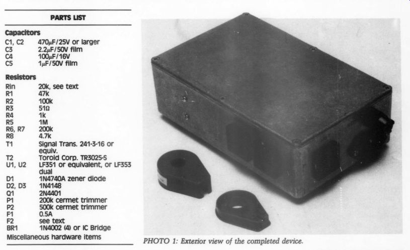
-------------- PHOTO 1: Exterior view of the completed device.
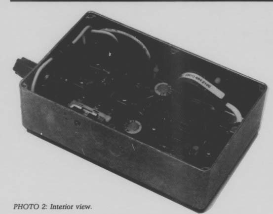
-------------- PHOTO 2: Interior view.
The output of U2 is fed to a limiting resistor R8 and then to the base of a control transistor Q1. To prevent the comparator ’s negative swing from affecting Q1, I connected a signal diode from emitter to base, thus the transistor is turned off with approximately -0.6V DC.
Now Q1 acts to turn on/off a solid state relay (SSR), which in turn controls the switched outlets. An appropriate re lay with a protective diode could be used in place of the SSR.
Fusing is important and requires some consideration. In the units I built I used a 25A SSR, hence I used a 20A type ABC fuse to protect the solid-state relay and the power circuit. I used a small fuse to protect the internal op -amp supply.
Adjustments
To test the unit before operation, plug it into the wall outlet and plug the load (preamp, lamp, or whatever) into the unit ’s ‘on ’ outlet. Connect a volt meter to ground and test point 1 (TP1).
The secondary center-tap of the small transformer is a good ground for testing.
Measure the voltage at TP1 with the load on, then with the load off. The trip point will be:
trip point = [Von - Vor + Vor] /2
If Voss is zero, use about 0.5V rather than zero in the formula. Now adjust P2 to read and set the trip point voltage at TP2. Now set the gain of U1 with P1 so that, with the load on, at least 8V is observed at TP1. You may have to go back and redo the trip point.
If insufficient gain will not give at least 8V at TP1 with the load on, you may have to make another turn of the line wire through the current trans former. I have never had to go to three turns, but you could go as high as four.
With the gain of U1 all the way down, if you cannot go below 10V at TP1, R_in is the culprit. The value of R_in can be reduced, when the voltage from T2 is too high. You can go down to about 16-ohm. A single turn through the T2 center is indicated in this case, and I suggest a wire-wound 3W resistor for Rin.
Construction
The Photos show a unit built into a cast aluminum box, about 7.25 by 4.75 by 2 inches. I built the power and op amp circuits on a ‘perf-board’ with 1/10 -inch hole spacing. The board is wire wrapped, using 26-gauge Kynar insulated wire.
Mount the T2 current transformer with ‘standoffs’ and 4-40 machine screws. In most instances the trans former case may be opened carefully, depending on the amount of silicone rubber sealant used to keep the inner toroid from rattling. I have written the Toroid Corp. and suggested that holes for mounting would be useful. I drill 4-40 clearance holes 5/8 -inch from the flat end where the cord exits the case and 1/8 -inch from the side.
The box must be drilled and filed for the input power socket and the three output sockets. If you use square snap in outlets I suggest the use of a pillar file here. This file has one smooth side (that is, no teeth). The 15/16 -inch square cutouts for the outlets can be shaped quickly, and I would suggest also that you widen the sides of the holes toward the inside to allow the socket springs to hold better in the thicker metal of the cast box.
With an AC input socket you may use heavy-duty cords for heavier loads.
I have always used 12-gauge stranded wire for the AC power in the units.
Observe the color coding, using black for the line, and white for the neutral.
UK and European color codes are different and should be observed.
Supplemental Thoughts You can easily multiply the control function. Plug an AC-operated SSR or a sequencer into one of the switched outlets of the sensing device and connect it to a different wall outlet, thus multiplying the AC outlets. A review of my article, ‘Using Solid-State Relays: Safe Power Control, ’ (TAA 2/86) might be helpful.
Although no specific resistor type is specified in the parts list, I have made use of 0.25 W 1% metal film types, since I had them in stock. This is not an audio channel, so carbon types are acceptable. I have used a Wima MKS 1uF capacitor for C5 with complete success, and it is small. I suggest a zero voltage on/off type SSR.
After this article was submitted, the Toroid Corp. of Maryland have notified us that a new case for the TR 3025-S Current Transformer has been developed. The new case includes external mounting ears, which will simplify the use and construction of any controlling device using it.
The photo of the external view of the controller box includes a case top and bottom of the older transformer. The case was illustrated to show the ‘canoe’ shaped spaces where mounting holes were drilled. Of course the new case precludes the need for this modification.
SOURCES
Toroid Corp. of Maryland 6000 Laurel-Bowie Road Bowie, MD 20715-4037
Signal Transformer 500 Bayview Ave. Inwood, NY 11696
Mouser Electronics 11433 Woodside Ave. Santee, CA 92071
Digi-Key P.O. Box 677 701 Brooks Ave. South Thief River Falls, MN 56701-0677
FOOTNOTE
1. Jung, W., and H. Childress, ‘POOGE-4: Philips/Magnavox CD Player Mods,’ TAA 1, 2/88.
Also see:
A TAPE CALIBRATION OSCILLATOR, By Reg Williamson