
.
BY FERNANDO GARCIA VIESCA
GAIN CONTROL is a designer's dream. The possible advantages are a neater panel layout, micro processor control of gain settings for automatic alignment, storing parameters for later recall, eliminating the wear and tear associated with mechanical potentiometers and so on.
For audio use, where multiple pots are common, you would doubtless wish to include such a worthwhile feature in your design. Problem is, how can we implement it? Fortunately, semiconductor vendors come to our rescue. For example, National Semiconductor offers the LF13006 and LF13007 digitally con trolled gain sets intended to be used with an external op amp, therefore al lowing amplifier gain to be set digitally.
This IC (Fig. 1) includes an array of resistors, digitally selectable via analog switches driven by a binary decoder. By selecting the appropriate data bits in the three digital inputs, binary scaled gains from 1 to 128 may be selected (for the LF13006), or you may use common attenuator sequences of 1,2,5,10,20,50, 100 (for the LF13007).
FIGURE 1: Digitally controlled gain set allows gain variations of an external
op amp to track the three digital inputs.
Although these ICs are an important step forward, they are not suitable for use in audio circuits. Seven steps may be enough for the volume control of a TV set, but certainly are not adequate for an audio system. Also those gain sets are not true potentiometers, with which we can lower the gain to zero.
---------------
ABOUT THE AUTHOR
Femando Garcia Viesca resides in Mexico and is an electrical engineer with broad experience in industry. He is currently engineering manager for General Instruments' assembly plant in Mexico. He has written for a wide variety of electronics journals and has a long standing love for audio.
----------------------
And finally, digital control of the circuit is oriented toward the use of some form of microprocessor, and not easily adaptable for discrete logic control.
A Better Solution
Xicor offers the X9103 (10k-o), X9503 (50k-o) and X9104 (100k-o) digitally controlled potentiometers, a large improvement over the National Semiconductor circuits.
These units offer several important advantages. First, they are actual potentiometers with two free ends that may be connected as you wish (observe the maximum voltage ratings) and a wiper.
Second, the internal resistive array has 99 elements, offering a resolution that, at least for audio use, we may consider continuous since the human ear cannot resolve such small increments.
Third, control is easy because the chip's internal counters and decoders are driven by a single clock pulse, an up/down signal and a chip select en able. The internal counter has steering logic to prevent it from over- or under flowing; when it has reached the top or bottom of the counting sequence, it will stop. Thus, you avoid a common pitfall in these circuits-if you overflow the counter, the wiper goes from full resistance to zero resistance. (Imagine you are lowering the volume of your amplifier and suddenly it comes at full power, blowing apart your driver cones and your eardrums.) Fourth, and perhaps most important, the circuit features an internal, batteryless, nonvolatile memory that stores the current wiper position, retains it after power-off and restores it at power-on. Thus, it functions exactly as mechanical potentiometer.
Xicor, a leader in the development and manufacture of EEPROMS (Electrically Erasable Programmable Read Only Memory), claims the memory will retain its contents for 100 years. By then, the amplifier will have passed to a better life. Wiper position recall is automatic at power up and transparent to the user. The IC is powered by standard logic +5V, and the potentiometer section can handle -5V to +5V. The block diagram shows the circuit (Fig. 2); the resistor array uses thin film types, giving excellent temperature compensation and good linearity.
Pot Logic

FIGURE 2: Block schematic of the X9MM family of circuits. The total
array resistance comes in three models: 10k, 50k and 100k.
This 8-pin IC is very easy to use, but we should understand the pin assignments:
Pin 1 (INC)-a negative edge clock pulse will move the wiper position (in other words, increment the internal counter). The actual direction of the move is controlled by another pin.
Pin 2 (U/D)-a logical 1 appearing at this input will control the wiper in the upward direction. Similarly, a logical zero will control the wiper in the downward direction.
Pin 3 (Vu4)-high end terminal of the potentiometer.
Pin 4 (Vss)-ground.
Pin 5 (Vw)-wiper end of the potentiometer. Wiper residual resistance is 400. Absolute maximum current is 1mA.
Pin 6 (Vi )-low end terminal of the potentiometer.
Pin 7 (CS)-chip select. The device is selected when this input is at a logical zero. The current counter value is stored in the nonvolatile memory when CS is returned to high with INC also high.
Pin 8 (Vcc)-supply voltage, +5V.
Mode selection is:
CS INC U/D MODE L Y H Wiper Up L V L Wiper Down A H X Store Wiper Position L: Logical 0;
X: Don't care;
Y : Negative going transition of clock pulse.
A : Positive going transition of clock
------------------

FIGURE 3: Simple demonstration circuit for electronic potentiometer used
in stereo volume control.
---------------

FIGURE 4: So, volume control may be achieved with this circuit.
Normal opm t+ bt itd Identical circuits may be duplicated for bass, treble
and so on.
Simple Operation
In a straightforward circuit (Fig. 3) an LMS555 timer generates a 5Hz square wave that the increase switch feeds to the INC pin 1 of U2 and U3. Select up or down (ground or open) with the Up/Down switch, also feeding both ICs. You can modify the volume of the right or left channel with the right/left switch. All logic inputs are pulled up high via resistors R3 through R6, so a very simple switching scheme is used.
In Fig. 3 I've not shown any connections to the potentiometer section of the IC. This depends on your application and I'll show you some later; right now we're interested in the circuit control.
Though simple and useful for demonstration purposes, this circuit is a little cumbersome to use. For example, you must remember to press (open) the increase pushbutton before deselecting the circuit. Remember that the INC pin should be at a logical 1 when you deselect the chip to store the wiper position into memory (easy to forget).
Also, you can control the left or right channel, but not simultaneously. For a better and more elegant solution (Fig. 4), we can include some logic to properly control the circuit and a two-speed wiper control to make high resolution adjustments without waiting forever for full wiper adjustment.
The circuit works as follows: a clock circuit using timer LMS555 and associated resistors and capacitors generates a square wave of about 5Hz that is fed to a NOR gate. This gate allows the clock to pass through only if the other input is at a logical zero, which happens if either pushbutton VOL UP or VOL DOWN is pressed.
Diodes isolate one pushbutton from the other, since the DOWN pushbutton also feeds the UP/DWN terminal (pin 2) of the electronic potentiometer. The clock signal from the NOR gate output feeds the INC pin of the electronic potentiometer and also feeds transistors Q1, Q2, which discharge timing capacitors C3, C4.
The RC time constant is larger than the period of the clock pulse, therefore a logical zero appears at the output of Schmitt trigger U3d, U3f, enabling the potentiometer via the CS pin. When no pushbuttons are depressed, the INC stops receiving clock pulses and goes to a logical 1, and C3 starts recharging; the net result is the CS signal stays at logical zero for a few moments after the clock has stopped, enabling the wiper position to be stored inside the internal nonvolatile memory.
Subsequent circuits may be repeated as many times as necessary with a single clock source.
Since the clock is relatively slow, to allow fine trimming we must provide a way to speed it up for coarse tuning in minimum time. Therefore, I included another pushbutton, labeled SLOW/FAST, to ground the base of p n-p transistor Q3, which effectively parallels resistors R2 and R3. Now the timer clocks about five times faster.
Of course, you may experiment with resistor values and find slow/fast speeds that better fit your application.
And if you are proficient with micro processors, you may implement full automatic control.
An Audio Circuit
So far we have covered the electronic potentiometer's control aspects. The actual potentiometer section may be used in an audio circuit in exactly the same way as its mechanical counter part. Volume and tone controls, panning and so on can be accomplished, but do not allow the signals to swing more than +5V.
Frequency response and harmonic distortion are shown in Fig. 5. As you see, the frequency response is more than adequate for hi-fi equipment, though harmonic distortion will slightly degrade equipment performance.
The noise specifications, about -65dB below 1V, may not live up to your high standards. Also, the circuit is linear taper, but a log taper is required for audio gain controls. however, you may easily approximate the log taper by including a resistor as shown in Fig. 6.

FIGURE 6: Audio taper from linear taper may be achieved with circuit as shown.
----------------

TEST CONDITIONS
Vee = 5.0V
Temp. = Room
Wiper @ Tap 50
Vy =0.5V RMS
Normalized (0 dB @ 1 kHz)
Test Circuit #6
FIGURE 5: Frequency response and harmonic distortion plots.
---------------------
This noise performance and the need to limit voltage swing may not appeal to some. you may prefer to adjust a DC voltage that in turn feeds a DC con trolled gain stage. Many variations of DC gain controllable amplifiers are available, such as the Motorola MC3340 and the National LM1036, as well as designs made with OTAs. I'm certain some TAA readers will have other circuits to share.
Further Applications
You may find the electronic attenuator's lack of visual feedback is not a problem in some applications, such as fully microprocessor controlled gain.
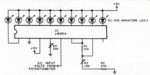
FIGURE 7: Bar-graph meter may be used to monitor actual wiper position. This works when you use the potentiometer to control a DC voltage.
However, a visual indication is always welcome. You can easily include a bar graph meter to monitor the DC voltage (when the potentiometer is controlling an electronic DC attenuator). A simple bar graph, built around the LM3914, is shown in Fig. 7. You should know the a nonzero voltage.

FIGURE 8: Suggested connection for a DC-controlled attenuator. External trimmer
allows use of full resolution of the electronic potentiometer for attenuators
where its minimum gain is achieved at a nonzero voltage.
DC attenuator's maximum and minimum voltages that adjust maximum and minimum gain. Adjust potentiometers R3 and R4 so the highest LED lights up at maximum gain and the lowest LED stops glowing at minimum gain. When you are using the potentiometer for tone controls, adjust the shining LEDs so they are centered at zero dB gain. The bar-graph IC should be operated in the dot mode to minimize power drain and heat generation. The voltage supply should be at least 3V above the DC control voltage.
Circuit applications with a full fledged microprocessor control are virtually limitless. You could build a graphic equalizer that generates pink noise, evaluates the overall room speaker performance and then equalizes the output. Remote volume control would be another positive asset. We've all experienced the frustrating stand and sit situation to adjust volume and find that the response near the amplifier is not the same in our ‘sweet spot.’ With imagination, other parameters may be easily controllable. I hope this short article fuels your imagination.
REFERENCES
1. Xicor Data Book, Xicor Inc., 1987, pages 4-1-4-12 and 7-23-7-32.
2. Linear Supplement Data Book, National Semiconductor Inc., 1984.
Also see:
A MULTI-TONE INTERMODULATION METER, PART II., By Erno Borbely