THE ADCOM GFA-555 has become one of the most popular power amplifiers on the market in the last few years probably because of its performance and very reasonable cost. The ADCOM sales literature, showing a lightning bolt coming out of the amp, helped, too.
Within the bounds of expectation, the GFA-555 is powerful enough, though not truly 'high end' in quality. It lacks both sweetness and definition, particularly as the volume is turned up (and why else would someone buy a 200W/channel amp?). I was on the verge of trading it in when I saw an ad for modification by Musical Concepts which promised to tame this tiger's aggressive nature. By changing or adding different capacitors, their mod did sweeten up the sound considerably and made the amp quite listen able but did nothing for its limited resolution. Ultimately, I was led to try this power supply regulation mod and it has finally transformed the amp into a truly first class component.
As with virtually all modifications, remember that your warranty will be voided. By the time you are ready for this mod, however, the one-year warranty will likely be up.
--- --
ABOUT THE AUTHOR
J. Christopher (Kit) Ryan has been experimenting with audio equipment since his mid-teens (for almost 30 years). He has designed and built dozens of speakers, amplifiers and pieces of test gear. A graduate Naval Architect and Marine Engineer, he still finds time for his favorite avocation between house projects and raising children.
---- --
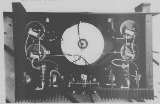
PHOTO 1: Top view of the author's modified ADCOM GFA-555 power amp.
Design Considerations
The block diagram in Fig. 1 shows where the new circuitry is added. In considering the range of possibilities for how it could be designed, I settled on the following objectives, all of which were met in the final design:
1. Don't compromise output power.
Approximately + 57V peaks are needed at the amp's output to meet its 200W (80) rating. Allowing for about a 3V drop across the output stage, 60V minimum must be provided by the regulator. More would provide additional ''headroom'' and is preferable. The raw supply provides +80V at no load, but drops to about + 65V at continuous maximum power out, so at most there is 5V for the regulator drop.
2. Retain the ADCOM’s high current output capacity. The literature says the output can produce 20A peak, 122A RMS.
This is in keeping with the safe operating area (SOA) for the output transistors, despite the fact that there are four NPNs and four PNPs per channel rated at 15A each. The regulator's pass transistors will therefore have to handle 20A.
3. Don't defeat the amplifier's protection features. These consist of 6A fuses in the power supply lines, thermal cut outs and SOA (safe operating area) circuitry within the amplifier.
4. It must fit! (inside the ADCOM cabinet, that is). My goal was to have the shortest wiring possible to reduce voltage drops, while using as much of the original raw power supply as possible to keep costs down. Also, since no additional heat would be dissipated, the existing heatsinks should be used for the power supply, too, if possible. The most straightforward scheme to accomplish this is to mount the circuit board on an aluminum angle that is attached to the back of the existing heatsink, as shown in Photo 1. This arrangement limits the board size to a maximum of 3" x 6", with only a 6" length available for power transistor mounting.
Pass Transistor Sizing
In looking over the design objectives, I realized the feasibility of the modification would hinge on finding a workable configuration for the as yet undefined pass transistors, so I'll discuss them first.
The governing condition for these transistors is to pass the peak current at the expected voltage without exceeding their SOA. In reviewing spec sheets for suitable power transistors I could see that no more than 10A could be obtained at a voltage drop of, say, 15V (estimated worst case expected at the maximum output condition; i.e., supply output voltage 60V with the input having dropped to 75V due to a heavy transient load).

FIGURE 1: Block diagram of the modified amplifier.
FIGURE 2: Safe operating area (SOA) for the 28SC2565 transistor.
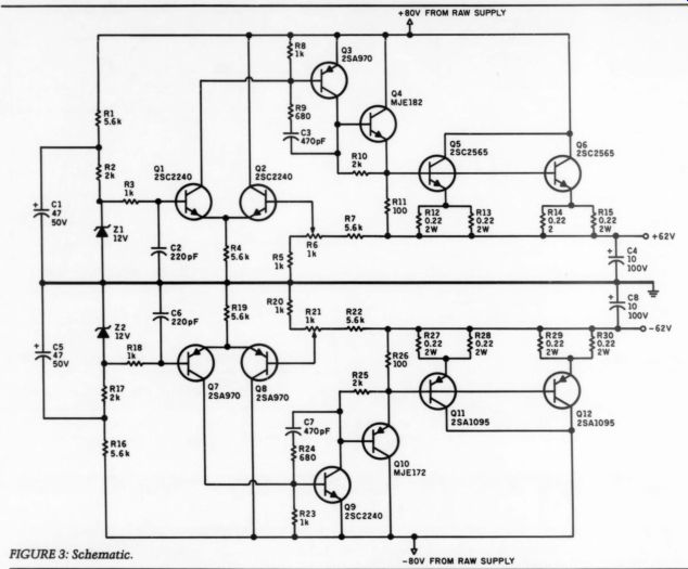
FIGURE 3: Schematic.
This can happen when aloud sound occurs during a relatively quiet passage, such as when the bass drum beats about six minutes into Part 2, ''The Sacrifice," of Stravinsky's Rite of Spring. Thus, a pair of pass transistors was the minimum I needed for each side of the supply, per channel, to meet the stated 20A requirement.
At first glance, I thought it sensible to use some of the same power transistors already used in the ADCOM-2S8B554s and 2SD424s. These have TO-3 case styles with minimum dimensions of 1 1/8" x 1 5/8" (including the insulator) and are a nuisance to mount. With four transistors per channel total, they simply would not fit within the space available on the 1" x 1" x 3/4" thick mounting bracket, the largest aluminum angle I could readily obtain that had enough thickness to carry the heat. As a solution, I used the rectangular style 25A1095s and 2SC2565s to save space while providing equal current handling ability. With an insulator, these transistors are less than 3/4, " wide by 1 1/2 "long and fit nicely on the 6" long aluminum angle. Figure 2 shows the SOA for these transistors. A check of power dissipation at the worst case 2/3 power out reveals a nominal 14W per transistor, well within its limits.
P TARMS x 8V drop across regulator Ww
"2 (half time each side of supply) x 2 transistors
= 14w
The rest of the circuit design is straight forward. The positive and negative sup plies are mirror images of each other, so I will describe only the positive supply.
The limited voltage drop available at maximum power virtually precludes “double regulation.'' It is probably not needed for a power amplifier anyway. A 12V zener diode serves as the reference for a differential amplifier, Q1 + Q2, whose output drives the voltage amplifier transistor Q3. R3 and C2 remove high frequency noise from the zener while R9 in series with C3 provide for a stable closed loop circuit with fast response.
-------------
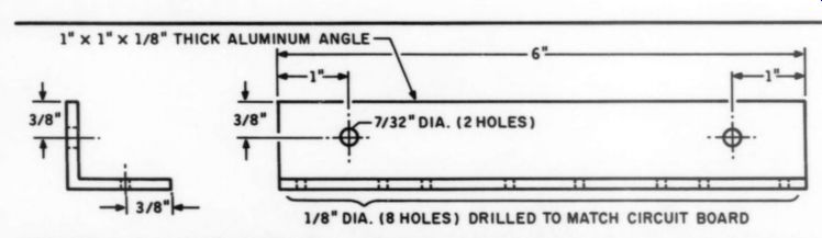
FIGURE 4: Detail of hole drilling on aluminum angle.
Note: Transistor hole spacing is not an integrated value either in inches (0.95") or in metric (24.4mm). First drill holes in the board to match foil pattern, then overlay board on aluminum angle and mark for drilling.
PARTS LIST
Resistors:
R1, R4,R7,R16, R19, R22 5.6k R2,R10,R17,R25 2k R3, R5, R8, R18, R20, R23 1k R9, R24 6800 R11, R26 1000 R12-R15, R27-R30 0.220/2wW*
*can substitute 0.19/3W wirewound for pairs of 0.220 resistors Zener diodes:
21,22 12v,0.5wW
Capacitors:
C1,C5 C2,C6 47uF, 50V electrolytic 220pF polypropylene, polystyrene 470pF polypropylene, polystyrene 10uF, 100V electrolytic C3,C7 C4,C8
Trimpots:
R6, R21
Transistors:
Q1,02,Q9 2SA970
Toshiba Q3,Q7,Q8 2SC2240
Toshiba Qa MJE 182 Motorola QS, Q6 2SC2565
Toshiba Q10 MJE 172 Motorola Q11,Q12 2SA1095
Toshiba 1k cermet, single turn
---------------
Emitter follower Q4 provides current gain and drives both the pass transistors, Q5 and Q6. Emitter degeneration for these comes from R12 through R15 and serves to balance the current between them. I prefer to use non-wirewound resistors, which are limited to .220 ohm minimum value, so they are paired to reduce total voltage loss at 20A peak output to only 1.1V. (Note: in the photo, I used wire-wounds because a parts shipment was delayed. They work, too, but will be replaced when the right ones arrive.) Potentiometer R6 permits a wide adjustment range. I set mine at + 62V to provide maximum headroom for the amplifier while leaving just enough, 3V, for the regulator's drop at full power out.
The low power transistors must all be able to withstand at least 80V, which limits the selection somewhat. While they are not too critical in other characteristics, the ones shown work well and are readily available. The 25C2240s used as Q1 and Q2 are the same ones used as the input differential pair for the main amplifier itself. Note that the Q4 driver transistor dissipates so little power, no heatsinking of any kind is required.
------- --------
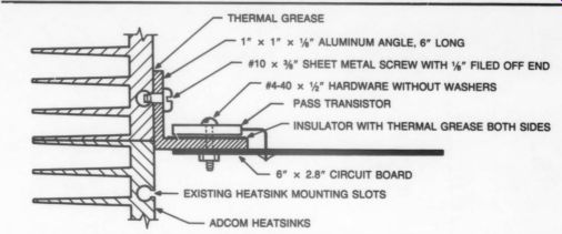
FIGURE 5: Mounting details-section view from top.
THERMAL GREASE; ALUMINUM ANGLE, 6" LONG
SHEET METAL SCREW WITH FILED OFF END
#4-40 x 4" HARDWARE WITHOUT WASHERS PASS TRANSISTOR INSULATOR WITH THERMAL GREASE BOTH SIDES
-------------------
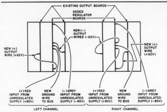
FIGURE 6: View of wiring inside back panel.
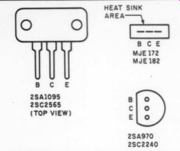
FIGURE 7: Pinouts for transistors (bottom view unless noted).
You probably noticed there is no protection circuitry. I believe the fuses to the power amp would blow before the SOA of the pass transistors is exceeded, so no special precautions are needed. I have used the amp well beyond clipping without any problems so far, but have shied away from an actual ''smoke test'' (i.e., shorting the amplifier output).
In terms of performance, the regulated supply reduces power supply fluctuations to the amp by over 40dB. At Construction Board layout is constrained by the positioning of the four pass transistors and the large emitter resistors. The arrangement allows for all connections to be at the inside edge of the board which makes wiring access somewhat easier. I use pins that stick up from the board to facilitate soldering of the wires, but with care you could push the wires through the holes and solder to the foil itself, as ADCOM did.
Drill the pass transistor mounting holes in the circuit board to at least 1/8" diameter, then drill and de-bur all the holes for the angle to match the board.
Use a 1/2" bit for the #4-40 x 1/2" hard ware. Also drill the two holes for mounting the angle assembly to the ADCOM’s heatsink using a 7/32" bit. Figure 4 shows the hole pattern. Since this is relatively thick aluminum, I recommend starting all holes with a pilot drill of smaller diameter, then changing bits to the finished size and re-drilling.
[A split point bit also does a good job here.-Ed.]
I suggest installing the pass transistors last since this step also includes attaching the board to the aluminum angle.
Bend the leads of these transistors so that all five holes line up (two for the screws and three for the leads). Then, assemble them with insulators through the angle and the board as shown in Fig. 5. Use thermal compound on both sides of the insulator.
By the way, these insulators are hard to find so try to get them when you order the transistors. In a pinch, a cut off TO-3 insulator will work but use a meter to make sure the collector is not grounded to the aluminum angle after you've tightened everything up. Keep the mounting nuts away from the board traces since they also can ground the collector. The foil layout shown gives adequate clearance for standard #4-40 nuts without washers.
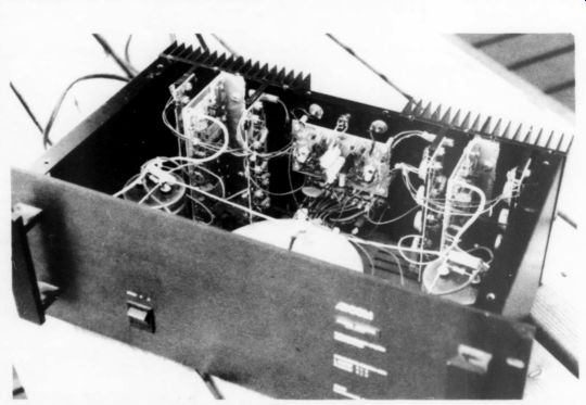
PHOTO 2: Back panel detail of the modified GFA-555. The added brackets and
boards sit between the two output power devices and are screwed into the heatsinks.
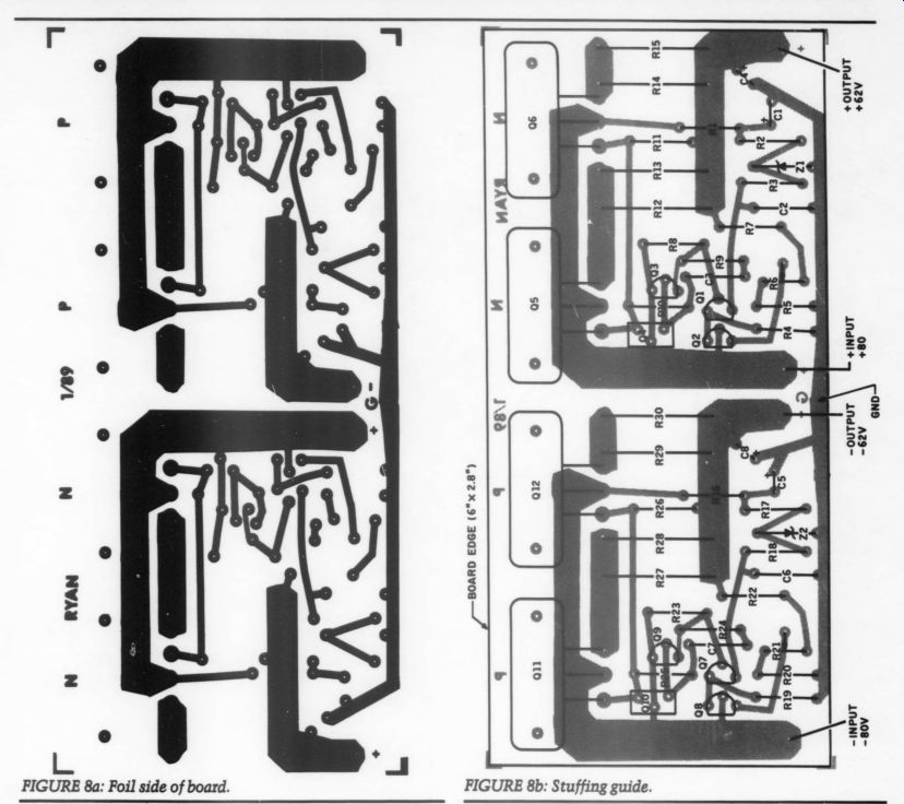
FIGURE 8a: Foil side of board. FIGURE 8b: Stuffing guide.
After board assembly, I strongly recommend bench testing each supply and calibrating the output voltage. One option for this is to take power from inside the ADCOM through a 100 ohm resistor if your bench supply won't go up to 80V, but BE CAREFUL TO AVOID SHOCK HAZARD! Installation First, turn off and unplug the power amplifier. Disconnect the speakers and in puts, too. Remove the entire cabinet top and the eight screws on the bottom used for attaching the heatsinks. Desolder only the big grey or red wire from each of the ADCOM's output boards which come from the raw power supply. There is enough wire flexibility to do the rest of the installation without any more desoldering.
Now, mount the assembled board units to the heatsinks tightly using thermal compound all along the angle. To mount them use #10 x 3/8" sheet metal screws that have had about 1/4" filed off the end so they won't bottom out in the shallow slots available in the heatsink.
While all the heatsinks are loose, solder appropriately heavy wire between the new boards and the output boards, noting carefully that they are mirror images of each other on opposite sides of the power amp (see Fig. 6). Then attach the original grey and red wires to the new regulator board; grey is the negative sup ply and red the positive.
You shouldn't have to cut or add to these wires unless the board layout was changed. Finally, add a short wire from the large bare ground bus to the new board. You can now reassemble the heat sinks to the bottom of the cabinet, leaving the top open. Photo 2 is a close-up of the left channel installation.
If you have one available, I suggest using a Variac to slowly power up the modified ADCOM, checking voltages at all four supply outputs along the way.
(That's how I safely discovered I had mistakenly wired the plus and minus backwards on one side of the amp!) Set the supply output voltages at about 62V.
Turn the unit off one more time, replace the top, re-attach the speakers and the in puts. You are now ready for listening.
Listening Tests
There is nothing subtle about this modification's effect on the ADCOM 555.
After ten seconds of listening, you will recognize the fallacy in the widely held high-end tenet, 'You can't make a good sounding power amp over 70W per channel." The accuracy and dynamic impact of this amp is truly awesome (as my kids would say). I have almost come to believe ADCOM's marketing hype that lightning bolts actually do radiate from this component. It can create shock waves that will make the glass doors of the china closet buzz, loosen the bolts on the rocking chair and practically homogenize your insides.
Sound
But let's talk about how it sounds. First, I offer a word of caution: if you like the warm, round, rich sound of accentuated bass, DON'T change your amplifier, be cause, depending on the rest of your system, all that will be gone. It will have been replaced by a tight, clear, punchy sound that puts you in the room with the instruments on the record. In other words, it makes the bass sound a lot more like real music than virtually all "mid-fi"' and most 'high-end' amplifiers. It is much easier to separate the bass guitar from the kick drum on popular music, for example. The tympani and bass drums on classical music sound like they were struck by a spirited human being (instead of a wimp).
Then there's the midrange. Clean, crisp snare drums. Try side 2 of the James Newton Howard and Friends record from Sheffield Labs or Steely Dan's Gaucho record which have particularly well recorded drums. It brings lifelike "plucking'' to the guitar strings of Michael Hedges' Aerial Boundaries and the mandolin-like instruments on Flight of the Condor. The voices of Carol Kidd or Ricky Lee Jones are almost touchable.
The orchestra in the Chesky release of Gershwin's American in Paris is simply right there in front of you in an incredible panorama.
The highs are noticeably extended, too. This is a two-edged sword. With the accuracy of the treble improved, the failings of digital recordings become all the more obvious. Stevie Winwood's two latest albums, both digitally mastered,
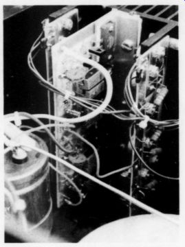
PHOTO 3: Close-up of the regulator board and bracket.
have plenty of zip but come across as rather two dimensional when compared to earlier efforts. Similarly, The Manhattan Transfer's Vocalese is too crispy and shallow after listening to their Extensions. It makes me sad to think that we will have to get used to that reduction in audio quality.
Summary
The transient response of the amplifier is dramatically improved, bringing increased resolution, imaging and sound stage definition with it. The best part is that these qualities are maintained from low volume levels right up to when the green ''overload'' LEDs on the front panel light up.
In the end, you will have to judge the measure of improvement for yourself.
My guess is that you will not be the least bit sorry for the effort expended to modify your amplifier.
SOURCES
Metal film resistors, polypropylene capacitors:
Old Colony Sound Lab PO Box 243 Peterborough, NH 03458
1-603-924-6371
Japanese transistors and .1 ohm/3W wirewound resistors (substitute for pairs of .22 ohm):
Consolidated Electronics, Inc.
705 Watervliet Ave.
Dayton, OH 45420-2599
1-800-543-3568
.220/2W metal oxide resistors:
Allied Electronics, Inc.
401 E. 8th Street Fort Worth, TX 76102
1-800-433-5700
.10/3W wirewound resistors (substitute for pairs of .22) and MJE 172/MJE 182 transistors:
Mouser Electronics
2401 Hwy. 287 North Mansfield, TX 76063
1-800-34-MOUSER
If there is sufficient reader interest Old Colony Sound Lab will make the circuit card and a kit of parts available for this project. Please use Fast Reply #423 if you are interested in a board only and Fast Reply #425 if you are interested in a board and a kit of parts.
Also see: