FAILSAFE LINE PROTECTION WITH POWER PRO
BY VERN L. MASTEL
IT IS A DARK and stormy night. Suddenly my lights flicker then die, along with everything else electrical in the house. Just as suddenly, the power returns, only to sputter and crash three more times in 30 seconds before the utility company's hardware gets things under control. As I listen to my electrical devices getting kicked in the teeth, I think, there's got to be a better way to protect them. The above incident actually happened to me, as I'm sure it has happened to you more than once. It lead me to design the surge suppressor described below.
Power Pro is a surge protector with AC line cutoff built into it. Two circuits are presented: Power Pro I, which has a manual reset, and Power Pro II, which has an automatic line reset.
The Basic Design
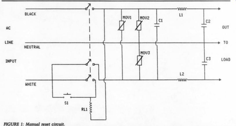
Both circuits share a common design (Figs. 1 and 2). Metal oxide varistors (MOVs) are used for line voltage clamping, with inductors and capacitors used for line noise filtering. The MOVs are wired from both hot and neutral to ground, and from hot to neutral. This gives both common mode and differential mode spike suppression. No matter which line(s) may carry a spike, it will be clamped to the maximum voltage of the MOVs used. The inductors and capacitors form a low-pass filter which effectively suppresses electromagnetic interference (EMI) which may be riding the power lines.
Power Pro I
The manual reset of Power Pro I is quite simple. A multipole relay switches both sides of the AC line and is wired to be self-latching. Once pulled, it will re main so until the power is removed. If the power fails for the briefest instant, the relay drops out and will not reconnect until somebody pushes the button, S1. For many loads, this is an accept able approach.
FIGURE 1: Manual reset circuit.
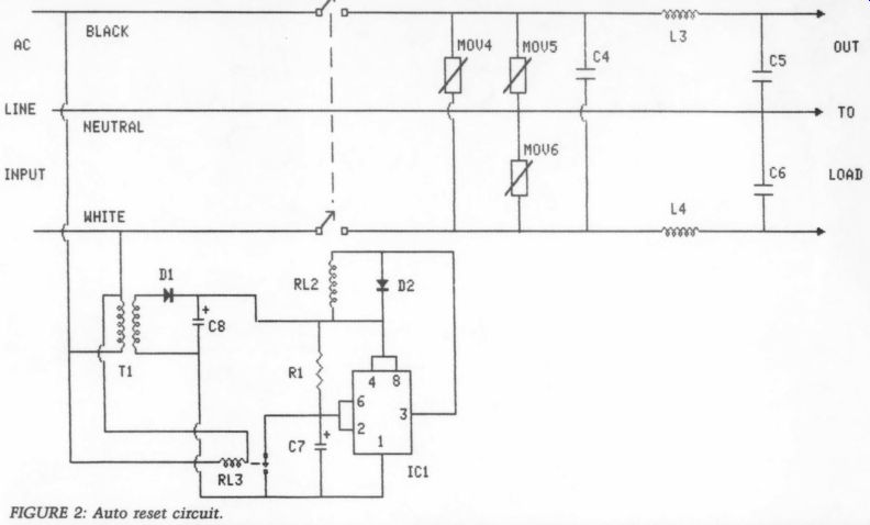
FIGURE 2: Auto reset circuit.
Power Pro II This is an automatic reset protector.
The unit has a time delay circuit that waits 45 seconds before it reconnects the AC line to the load. The time delay circuit is built around the workhorse 555 timer. There is a twist to the de sign, however. A standard power-up de lay timer cannot rapidly cycle and still be expected to deliver its time delay.
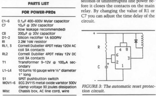
(Refer to Fig. 3.) When power is applied,
--------------------
FIGURE 3: The automatic reset protection circuit.PARTS LIST--FOR POWER-PROS
0.1uF 400-600V Mylar capacitor
10uF 20V capacitor (low leakage recommended)
200uF @ 20V capacitor
Silicon rectifier 1A 600PIV 2.2M YAW resistor
Cornell Dubelier
4PDT relay 120V AC coil 3A contacts Cornell Dubilier 4PDT relay 12V DC coil 3A contacts Transformer 9-12V @ 100A secondary 10 turns 16 gauge wire 2” diameter 1” long SPST pushbutton switch ECG 2V115 metal oxide varistor 300v clamp voltage 30 joules dissipation
Chassis box, AC line cord, wire
-------------------
the capacitor is charged through R, and when it reaches the trip voltage of the internal 555 comparator the output goes low and the relay pulls.
If you remove power and reapply it quickly, say, in one or two seconds, the relay will pull immediately because C is still charged. Figure 2 shows an additional relay RL3 wired for normally closed operation. This is added to force the immediate discharge of C7 when AC power fails. With RL3 in the circuit, the timer will always need at least 45 seconds of uninterrupted line power be fore it closes the contacts on the main relay. By changing the value of R1 or C7 you can adjust the time delay of the circuit.
Construction
The prototypes are built with vector board and mounted in a steel cabinet.
Because the units handle AC line power, I used a railroad rack wiring layout.
Three busses of 12-gauge wire run from input to output, interrupted only by the inductors and the relay. The MOVs and capacitors are soldered just as they are shown in the schematics. The inductors are ten turns of 16-gauge wire wound 0.5” in diameter. If you have access to toroids, you can increase the inductance by using one as a form. I have two versions of the design, one with 1” OD toroid ferrite cores and one with the air core coils. Though I can't detect any difference, the increased inductance of the toroid certainly can't hurt.
++++++++++++++++
Also see: