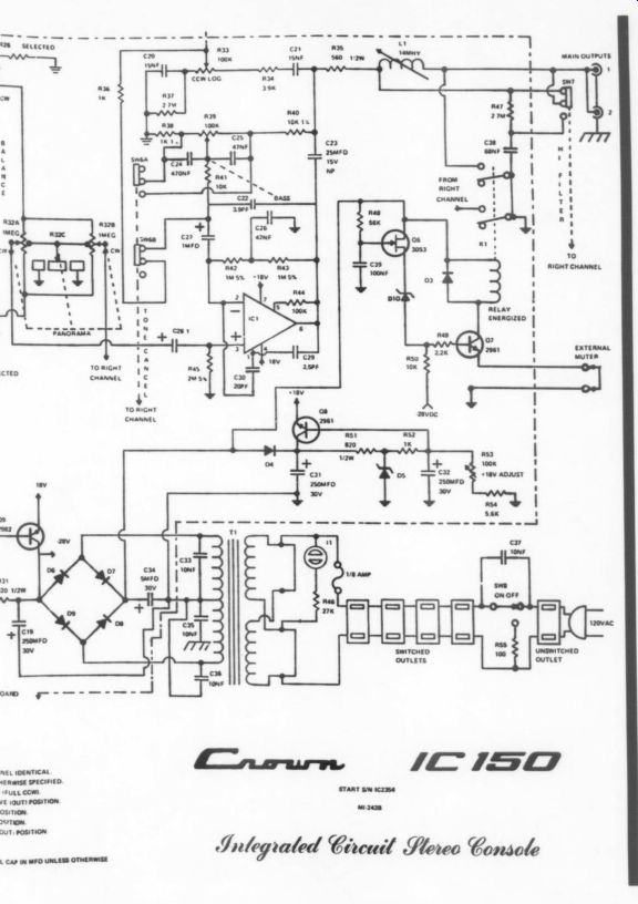
The CROWN IC-150, one of the premier preamplifiers of the early 1970s, compared favorably to the Audio Re search model of the time. The specifications of the IC-150 still compare with the best of today's units (Table 1).
----
TABLE 1
IM distortion: 0.002% @ 10V output
Phono S/N ratio: 85dB below 10MV
Max. output: 10V from 20Hz-20kHz
Phase shift: +5° from 20Hz-20kHz
Slew rate: 4.25V/ u-sec
----
While the unmodified Crown featured an unbeatable design in 1974, its sound was not as good as its specifications suggested. Today several units with similar specifications sound much better. I decided there was a good chance to improve the IC-150's performance at a minimal cost. Those on a budget may want to consider buying a used Crown (about $100) and performing the modifications described ($50-$100) as an alternative to buying an Adcom ($500) or other good quality, modern preamp.
Following principles outlined in TAA, 1 rebuilt the phono preamp section. Because I use the Crown as a “pure” phono preamp, I completely by passed the sophisticated and complex controls of the high level section to eliminate their colorations. Audible quality after modification is now as good as any preamp I have ever heard, better than my CD player in all respects except S/N ratio.
ABOUT THE AUTHOR
Mr. Buschmann is a chemical engineer de signing air pollution control equipment, whose interest has always been divided be tween electronics and chemistry. He built his first crystal radio kit at the age of seven and for a time held an amateur radio license. During college Mr. Buschmann subscribed to TAA and built his stereo components from kits. After his subscription lapsed, he 'moved up’ to high quality commercial equipment. He has since re-subscribed and rebuilt almost all his commercially-made components. Mr. Buschmann, age 35, is married and has three little girls.
Isolation Capacitors
The coupling capacitors, C12 and C13, were tantalum bead types. Because of their known audible effects they are the first area for improvement. Rather than simply replacing them with polypropylene (P-P) caps, which are much better but still less than perfect, I replaced them with short wire jumpers. This re quires other circuit modifications to avoid passing any destructive DC transients to the power amp.
Switch SW1A normally grounded all unused inputs and outputs in the preamp. I disabled it by bending the ground finger out of con tact with the rotating part of the switch.
I bypassed the phono selector switch and hard-wired the inputs to the phono board.
The values of R23 were trimmed to yield approximately equal ( 50mV) DC offset in the output of both channels. On my unit this required 200k in the left channel and 169k in the right. The resistors used were metal film.
I carefully adjusted the negative power supply voltage to bring the DC offset at the output of each channel to within 50mV of zero.
Check this adjustment every time you use the unit (before the power amp is turned on) as it tends to drift.
I altered the primary power connection to the preamp so it re mains energized whenever the unit is plugged in. This allows the preamp to stabilize over time while still permitting the convenience of using the front panel power switch to turn the rest of the system on and off.
I also replaced R13 and R14 with jumpers. They did not appear essential to the circuit operation and were less than ideal sounding, carbon composition types.
The result of these changes is dramatic. Improvements in clarity, focus, and transient response are such that the sound might be coming from a different piece of equipment. In addition, the much lower source of resistance of Q4 in the new circuit results in an improved signal to noise ratio.
Feedback Capacitor
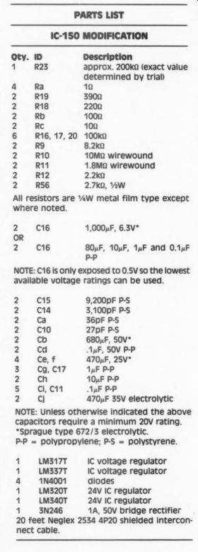
Next, I wanted to eliminate or replace C16, a large value (500uF) electrolytic in the feedback path and also a likely source of coloration. I wrote a short computer program to calculate the frequency response of the feedback net work. This permits time-saving simulation of the effects of substitutions of components. It turns out that replacing C16 with a smaller value film type will roll off the low frequency response of the preamp. I therefore assembled a composite of the largest film caps I could find. Polypropylene film caps of 80, 10, 1 and 0.1uF were used. The individual film caps have - 1dB points of 100Hz, 800Hz, 8kHz, and 80kHz respectively; while the composite is down 2.5dB at 20Hz.
Several alternatives were tested:
1. I used the film caps to bypass C16. The effect of the bypass capacitor is fairly subtle. Improved transient response in the upper bass and an over all smoothing of the sound are the main benefits.
2. I replaced C16 with a higher quality electrolytic capacitor having low inductance and low ESR. I used a 1,000uF 6.3V Sprague series 672. There is a noticeable improvement in clarity, openness, and definition across the tonal range as a result. The low bass is extended and seems more solid. Stereo imaging is more stable throughout a wide area of the listening room.
3. I used metal film capacitors to replace C16. Not surprisingly, the P-P caps sound best when used alone. Transient response is excellent, boominess is eliminated from the bass and the extreme highs are extended. Overall transparency is slightly improved over the better quality electrolytic caps.
There is however, some loss of impact in the low bass.
An irritating grittiness in the highs was traced to a resonance at 53kHz between the capacitor and the inductance of the wiring. The cure is placing a 10 Corning resistor in series with each terminal of the capacitor as close as possible to the case. The resistor reduces the Q of the resonance from 62 to 0.002.
The resulting high end is clear, razor sharp, but liquid and musical. These resistors also work well with the electrolytic cap, which originally resonated at a much more annoying 16kHz.
The large value P-P caps are quite ex pensive, $55 (total) from Madisound and physically larger than the power supply filter caps in most power amps, which requires mounting the caps out side the preamp cabinet. I do not recommend this modification as cost-effective or practical. Replacing C16 with a better quality electrolytic will yield 80% of the improvement at 10% of the cost of the P-P caps.
As a result of the calculations on the feedback network, I modified some of the other component values to improve the RIAA accuracy. C15 is changed to 9,200pF, C14 is increased to 3,100pF, and R19 is changed to 390 ohm. I jumpered R21 and increased R18 to 220 ohm to yield a fixed gain, correct for the phono cartridge used. All the capacitors I used are polystyrene and all resistors are metal film.
The before and after frequency response is shown in Table 2. 1 was surprised to find that 0.1dB changes in response are clearly audible. The upper bass and midrange sound much smoother, while the uppermost highs are ex tended. The front-to-back imaging information, a subtle change in frequency content and mixing technique, becomes obvious when not masked by system response variations.
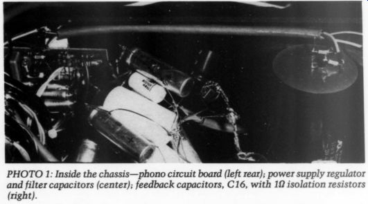
PHOTO 1: Inside the chassis-phono circuit board (left rear); power supply regulator and filter capacitors (center); feedback capacitors, C16, with 12 isolation resistors (right).
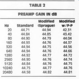
TABLE 2 PREAMP GAIN IN dB
-------- Fig. 2
--------
----------------------
PARTS LIST
IC-150 MODIFICATION
NOTE: C16 is only exposed to 0.5V so the lowest available voltage ratings can be used.
NOTE: Unless otherwise indicated the above capacitors require a minimum 20V rating.
Sprague type 672/3 electrolytic.
P-P = polypropylene; P-S = polystyrene.
------------------
Wiring and Contacts
I replaced the cable from the turntable to the preamp with Neglex 2534 blue, and also the cable from preamp to power amp. An inspection of the old turn table cable revealed a center conductor of #30 copper-weld. It is amazing that an otherwise high quality piece of equipment was crippled by such an obvious design error.
I soldered the new phono cable directly to the proper terminal strip in the turntable and also to the input of the phono preamp board. A 36pF polystyrene (P-S) cap was added at the preamp input to properly load the cartridge. I carefully soldered the headshell wires to the cartridge pins. The tonearm plug connector was treated with TV tuner cleaner/lubricant. A variety of these cleaners are available. They seem to be very effective at reducing contact resistance and are easy to use.
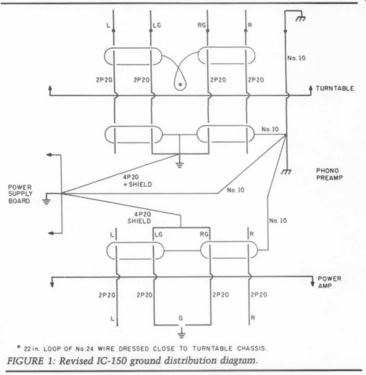
I soldered the preamp output cables to the appropriate terminal of the selector switch and to the input terminals of the power amp. Each of the signal output wires from the phono board to the selector switch I replaced with a 2P20 twisted pair stripped from Neglex cable. The new wiring requires revision of the circuit ground distribution to reduce hum and RFI. The final configuration is shown in Fig. 1.
Several of the phono preamp transistors (Q2, Q3) were plugged into sockets made of a ferromagnetic material. I re moved these and soldered the transistors directly to the board.
This series of modifications also yields a dramatic improvement in clarity, and focus, and adds a sense of air to the sound that was missing previously. An amazing amount of musical detail is revealed. Transient response is at times breathtaking. Capacitive loading on the phono cartridge I found to be very critical. A mellow sound quality results from no additional capacitance while 100pF results in an un pleasant peaky high end.
Power Supply
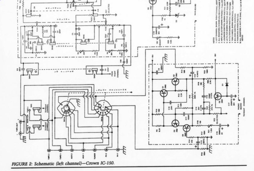
The original design (Fig. 2) provided an adjustable + 18V regulated supply with reasonably good filtering (less than 0.5mV of ripple after regulation). How ever the simple pass transistor design without output bypass capacitors and the 10” of #24 wire between power supply and the phono board did not seem likely to ensure a low supply impedance at the phono preamp board.
I retained the original regulated sup ply to provide an adjustable reference voltage for LM317T and LM337-T IC regulators. These regulators are located near the phono board and their outputs connected to the preamp with 1” of #20 wire. I brought over the unregulated + 28V supply voltage from the original filter capacitors using a 2P20 twisted pair within a Neglex cable for each.
I added protection diodes and liberally-sized electrolytic bypass capacitors with P-P shunts at the output and reference terminals of each regulator (Fig. 3). 1 soldered the ground side of each capacitor to the main board ground.
Calculated impedance of the new supply at the preamp is now under 20 m-Ohm from 10Hz up to 100kHz.
I discovered the hard way that the original transistor regulators cannot provide the peak current required to initially charge the large value caps now at their outputs. After experimenting, I installed 100-ohm resistors as shown to limit the peak current. Listening tests and calculations based on the application literature for the IC regulators indicate no loss of regulation performance due to these resistors.
Because of their successful application to op amps I decided to add 0.1uF P-P caps from the circuit board, + 18V power trace near Q1 and Q2 to ground and from the - 18V trace after Q5 to ...
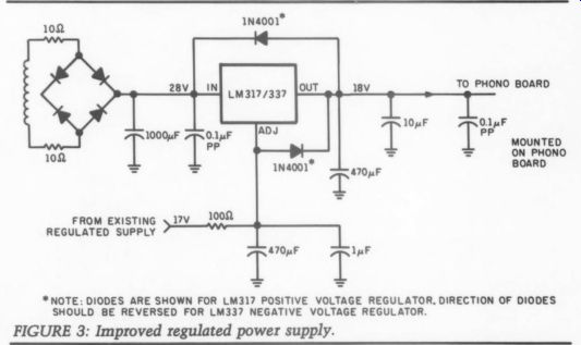
-----------* NOTE: DIODES ARE SHOWN FOR LM317 POSITIVE VOLTAGE REGULATOR, DIRECTION OF DIODES SHOULD BE REVERSED FOR LM337 NEGATIVE VOLTAGE REGULATOR.
FIGURE 3: Improved regulated power supply. -----NEGATIVE SUPPLY SHOWN, POSITIVE SUPPLY SIMILAR
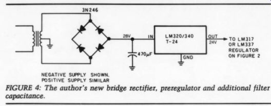
FIGURE 4: The author's new bridge rectifier, preregulator and additional filter capacitance.
... ground. These caps were located on the foil side of the board using 1/4 " leads insulated with spaghetti tubing. Separate caps are required for the positive voltage on the left and right channels be cause of the wide separation of the Q1 and Q2 locations on the two channels.
I added a 1uF P-P bypass around C17, and removed C9.
After studying the application literature on the IC regulators it appeared their output regulation was somewhat dependent on the stability of the unregulated supply to them. Calculation of the variation of the +28V supply versus preamp output signal revealed this was indeed limiting the performance of the regulators. I increased the unregulated supply filter capacitance to 1,000uF. This stabilizes the DC voltage acceptably, as well as reduces ripple. In order to limit the surge current at turn on, I added 100 resistors between the transformer secondary and the diode bridge.
Results
There are several noticeable results of the power supply modifications. The first is a substantial improvement in low bass detail and impact. Plucked bass strings have a clear harmonic structure previously missing. The separate bass drums can be clearly distinguished, including various microphone techniques for them. There is a sense of effortless, low frequency power that is quite impressive.
SOURCES
Roden Electronics 205 Oklahoma Ave.
Knoxville, TN 37901 (615) 546-8755 (Semiconductors, film resistors) Shields Electronics 4722 Middlebrook Pike Knoxville, TN 37921 (615) 588-2421 (Semiconductors, film and wirewound resistors, polystyrene capacitors) Newark Electronics 6500 Papermill Rd.
Knoxville, TN 37919 (615) 588-6493 (All components except polypropylene caps and Neglex cable.) Old Colony Sound Lab PO Box 243 Peterborough, NH 03458 (603) 924-6371 (Small value ( < 14F) polypropylene caps, film resistors, Neglex cable)
Madisound Speaker Components 8608
University Green Box 4283 Madison, WI 53711
(608) 831-3433
Large value (> 1uF) polypropylene caps)
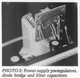
PHOTO 2: Power supply pre-regulators, diode bridge and filter capacitors.
The second impression is a seeming lack of highs. Extended listening has convinced me that what is missing is high frequency ringing or oscillation, caused by the previous high supply impedance. The actual musical high frequency information is present in its proper amount but without any extraneous interference.
The third improvement I observed is in solidity of imaging and resolution of ...
------------
TABLE 3
Cartridge: Shure 15-V MR
Turntable: Rabco ST-7
Preamp: Crown IC-150
Amp: Carver M400
Speakers: Cizek Model 1 (10” two-way, acoustic suspension)
Speaker Cables: 20P24 multiconductor
-----------
... fine detail in complex musical textures.
Individual instruments and voices are easily identified and localized even during densely recorded, high level climaxes. The characteristic timbre of various instruments also becomes more clear; that is, a flute is breathy, while a clarinet is reedy when playing the same note. There are many occasions when new instruments can be heard in old familiar recordings. Orchestral music and strangely enough, recorded applause, have a much richer and more realistic texture.
Next I replaced all the original com position resistors with Corning metal film types, the polyester cap used for C11 with a P-P, and the silver mica cap used for C10 I replaced with a P-S type.
This modification results in a smoother, better controlled bass and a less harsh but extended high end. The soundstage seems to have more depth and greater dynamic impact. It also sounds as though a distorted harmonic component of the music has been re moved from the upper midrange.
Plucked strings and piano notes have a clearly discernable attack, followed by a smooth decay. There is a slight improvement in the S/N ratio.
I later refined the circuit by adding a new bridge rectifier, preregulator and additional filter capacitance (Fig. 4).
This results in improved stability of the stereo image, more precise localization of instruments, and a better defined bottom end.
The sonic improvements described are not at all subtle and can be appreciated by anyone, not just the “golden ears.” My test system (Table 3) is not exceptional in any way. Yet the preamp modifications make a substantial difference in the sound quality. I en courage skeptical readers (I was one) to try some of the POOGE improvements on their equipment and judge for themselves.
++++++++++++++++
Also see: