BURNED AMPLIFIERS ...
... OR if you're very lucky blown fuses. When I repaired instruments for a local rock group, I often saw this problem. No matter how carefully the cables and speakers were inspected, a short developed now and then and blew something apart. That something would be, by a corollary of Murphy's Law, the most important piece of equipment.
Frustrated with this situation, I developed a circuit to protect the amplifier from a low impedance before the +12v +12v R1 amp is connected to the load. Originally conceived as a go, no-go verification, I realized it is so simple and inexpensive that it can be permanently retrofitted to any amplifier. If you lease sound reinforcement equipment, move your amps around, or simply wish to protect your home (or car) stereo, you'll find this circuit useful and easy to build.
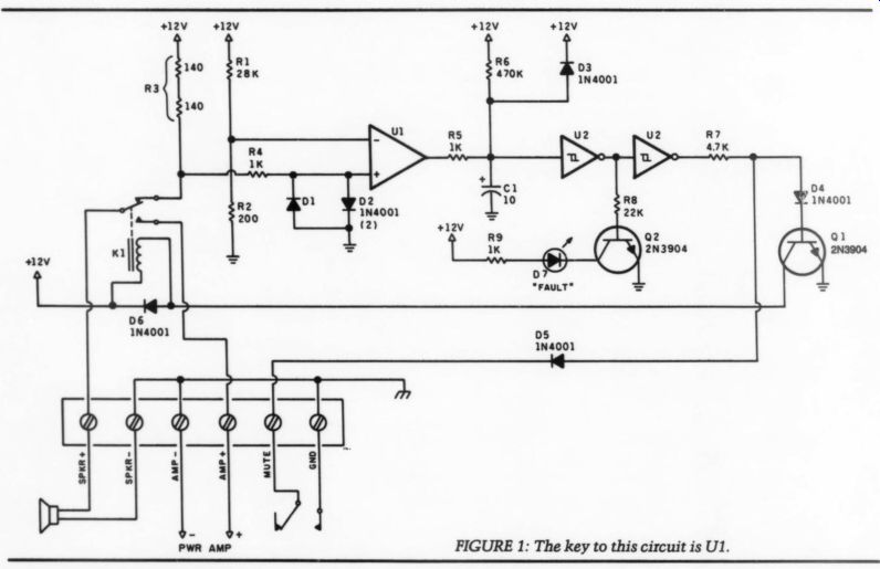
FIGURE 1: The key to this circuit is U1.
The Circuit
Simplicity is the name of the game (Fig. 1). Only two ICs and a handful of components are required. The key to this circuit is U1, which compares the volt age difference of a Wheatstone bridge. Its fixed leg is R1 and R2, connected to the voltage comparator's inverting input. This is our reference.
------------
ABOUT THE AUTHOR: Fernando Garcia Viesca works for General Instrument's assembly plant in Matamoros, Mexico. He has tinkered with electronics, and especially audio, since high school, where he built his first working project, a vacuum tube amp.
--------------------
PARTS LIST
AMPLIFIER PROTECTION CIRCUIT
Resistors R1 28 k-ohm, ½ W, 1% R2 200 ohm, 0.25 W, 1% (see text) R3 2800, 1W, 1% (see text) R4 1 k-ohm R5 1K-ohm
R6 470 k-ohm
R7 4.7 k-ohm
R8 22 k-ohm
R9 1 k-ohm
All resistors 1/4 W, 5% unless otherwise noted.
Capacitors C1 10uF, 25V, Electr.
Semiconductors
D1-6 1N4001 diode
Q1,2 2N3904 transistor
D7 Red LED
U1 LM393 dual comparator
u2 CDA4584 Hex Schmitt trigger
Miscellaneous
K1 12V DC coil power relay (see text) i! 6-terminal barrier strip
Optional 12v, 300mA, battery eliminator
-----------------
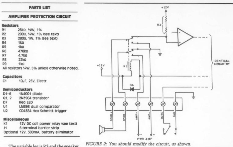
FIGURE 2: You should modify the circuit, as shown.
-----------------
The variable leg is R3 and the speaker, cable and crossover resistance. The value of R3 is dimensioned in such a way that whenever the speaker's DC resistance is higher than 2 ohm, the comparator's output, an open collector, is in a high impedance state, allowing C1 to be slowly charged via R4. Likewise, if the speaker's DC resistance is lower than 2 ohm, C1 is clamped to ground.
Suppose you have just turned on your amplifier. C1 is discharged, and the output of the second Schmitt trigger is at a logical zero. Therefore, the transistor is biased off, and the relay is not energized. Therefore, the speaker's coil is connected via the normally closed contact to the Wheatstone bridge and the comparator as described above.
Transistor Q2 is biased on and the fault LED lights. If there is low resistance, the circuit will stay that way until the condition is cleared.
A high impedance will allow C1 to charge, and after a few moments the relay will energize. The speaker's coil, is, therefore, connected via the normally open contact to the power amplifier and normal operation starts.
Since the Wheatstone bridge “sees” high resistance (as a matter of fact, in finite), the circuit will maintain transistor Q1 biased “on” and Q2 at cutoff.
We have achieved twofold protection: first, we have sensed the actual resistance before connecting the amplifier. Second, a time delay allows all the electronic devices to stabilize before the speaker is connected, and avoids the annoying turn-on “thump.”
Customize Your Circuit
You may be wondering why I chose 2 ohm as the trip point for the sensor, when most speakers are 4 or 8-ohm impedance.
The reason is: impedance is not equal to DC resistance. The DC resistance of the speakers is about half the impedance, therefore for 4-ohm speakers a 2 ohm DC resistance is commonplace. Anything less could damage the voice coil, cross over, or short a wire. Since there are exceptions, later on I'll describe how to customize the circuit to any particular resistance.
It's also possible to turn off the speakers via an external switch. If the “mute” terminal is grounded, base drive to the transistor is cut off, regard less the state of the previous circuit.
Since the switch may not actually be one, but a transistor that does not saturate completely to ground, a diode D4 has been included in series with the transistors base to increase the cutoff threshold. Diode D5 allows several channels to be simultaneously muted from a single switch.
Since the speaker may be on when you decide to mute it, the EMF (electromotive force) generated by its motion may generate a voltage spike that could damage the IC. Therefore, diodes D1 and D2 clamp to ground any dangerous voltages, without affecting nor mal circuit operation. Since it is difficult to find 1% (precision), AW resistors, R3 is two 1/4W units connected in series.
The circuit is so simple, any power supply in the range of 10 to 14V is appropriate, and suitable for automotive environments. Employing a Wheat stone bridge allows good accuracy with out regulating the voltage.
If the circuit is used in an automobile, the electric antenna output volt age, supplied by most car stereos will be sufficient. If this is to be used on an AC powered amplifier, use any 12V, 300mA battery eliminator, and plug it into the amplifier's switched auxiliary AC outlet.
Construction
Thanks to the circuit's simplicity, wire wrapping or a dedicated PC board might be used. Follow good soldering and handling procedures to avoid dam age. Make the short jumper wire from amplifier ground to speaker ground of at least 16-gauge wire; use the same for the relay wires handling high speaker currents. You don't want to waste audio power.
The circuits I built were located in side the amplifier, since those amps were also custom built. Locating the circuits inside your amp may not be advisable, since doing so will void your warranty. It's better to locate them in a small external box.
After a once-over of components, connections, and soldering, it is time to test. Do not connect an amplifier or a speaker yet. Place a 1 ohm resistor or a dead short between the speaker terminals in the protection device. Power up. Nothing should happen and the "FAULT" LED should light up. Remove this low value resistor or short.
After a couple of seconds, you'll hear the relay clicking. Now ground the mute terminal, and hear the relay de-energize.
Try your speakers. The circuit should operate. If it does not, even though you have good speakers, it's time to customize a resistor value.
With a digital multimeter (DMM), measure the DC resistance of your speakers. Be sure to subtract the test probe's resistance. Remember, this is a very low resistance measurement. Let's say the actual value is 1.20. Multiply this by 100 (120 ohm) and substitute this resistor for R2.
Please Note
Certain amplifier types operate in the bridge mode, which in simple words means both terminals are “live” with respect to ground. Grounding either one may cause amplifier failure--particularly true in high power car stereos.
Therefore, you should modify the circuit (Fig. 2). Basically, we are employing a DPDT relay slightly more expensive than the SPDT relay. The other pole grounds the speaker terminal during the measurement, and 'floats' it in normal operation. If you have no way of knowing the output configuration of your amplifier or would like a protective device for any type of amp, play it safe and use a DPDT relay.
Conclusion
The old adage, “better safe than sorry," certainly applies to protecting expensive audio gear. This simple circuitry gives you added insurance. It is important to note, however, the circuit will not detect certain reactive shorts (i.e. a defective crossover capacitor). Detecting those, however, would require a far more complicated and expensive circuit, which may not be justified.
++++++++++++++++
Also see: