Unlike a regular radio receiver, a two-way radio presents two separate power requirements to its power supply. In the normal standby (receive) position, the only drain on the power supply is the filament and plate power required by the receiver.
In the "transmit" position, however, the power supply (Fig. 4-1) must deliver not only filament and normal plate power, but also a negative bias (in some sets) to the final-amplifier grid as well as high B+ to the plates of the driver and final. These conditions require specially designed power supplies. Moreover, each manufacturer has his own design, thus the service technician in the field has to contend with an array of designs.
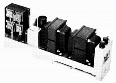
Fig. 4-1. AC power supply.
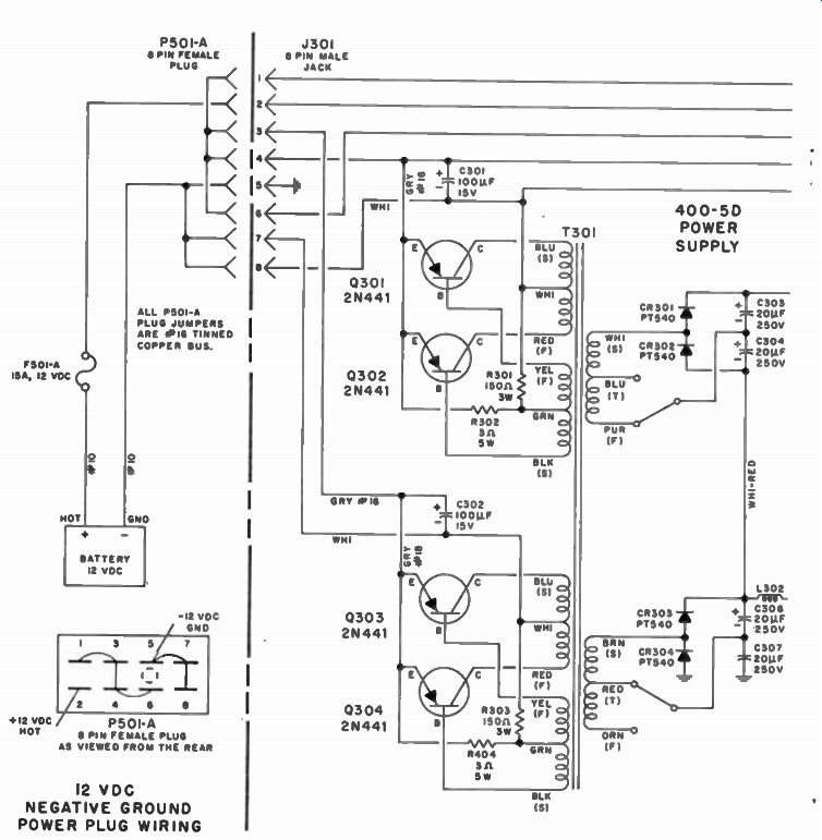
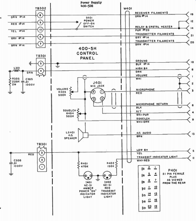
Fig. 4-2. Comco 400-5DH power supply and control head.
The different voltage conditions for "transmit" and "receive" are easily managed through the use of switching relays. When the push-to-talk switch on the microphone is activated, these relays transfer their contacts from the "receive" to the "transmit" mode. In some power supplies the antenna relay is on the chassis and it switches the coaxial antenna input from the receiver to the transmitter when the push-to-talk switch is activated.
THE COMCO 400-5DH POWER SUPPLY
The Comco 400-5DH (Fig. 4-2) is a combination transistor power-supply control box and speaker designed to supply the proper operating voltages and control functions for the Comco AN/VRç-51 series of equipment. The design and choice of components permit operation in the ambient temperature range from -30° to +60° C. Four quality transistors, type 2N441, in an electronic self-excited switching circuit provide AC voltages, which are stepped up by a toroidal transformer. (Important: This is really two 12-volt supplies connected in series or parallel.) After being rectified by silicon rectifiers, the voltages are filtered and then supplied to a receiver-transmitter unit. An automatic safety feature reduces the battery drain if the B+ lead is shorted, effectively protecting the components from damage. The power supply can be readily removed as a unit for servicing or replacement. All power leads are properly filtered to prevent radiation of the switching-frequency harmonics and both voltage regulation and operating efficiency are extremely good.
The power supply is designed to accept a DC input of either +13.6 volts (negative ground return), -13.6 volts (positive ground return), +24.6 volts (negative ground return), or -24.6 volts (positive ground return) from a battery-generator supply, in accordance with ETA standards. (These voltages are more commonly referred to as "12VDC" or "24VDC.") The tube filaments will accept either polarity-but the polarity of the voltage fed to the transistors must be observed. Polarity may be reversed by using jumpers in the primary input plug.
This unit normally is wired at the factory for a 12-volt DC, negatively grounded battery system.
Oscillator (Switching) Circuit
This oscillator (or switching) circuit closely resembles that of a push-pull vacuum-tube oscillator. When power is applied, more current will flow through one of the collector circuits (because of the minor dissymmetry of the two transistors) than the other. This current will induce a proportional current in the base winding, on the same transformer core. The winding connections are phased so that the polarity of the current biases the conducting transistor in the direction that increases its conduction, while biasing the other transistor in a direction which cuts off its collector current.
This process continues, with the collector current of one transistor rising (driving it further into conduction until transformer saturation occurs), and the collector current of the other decreasing. When transformer saturation occurs, the rising collector current can no longer induce a current in the base winding. As a result, the bases of both transistors return to their normal bias. Because its collector is at a high negative bias, the nonconducting transistor will start to conduct and the conducting transistor will be cut off. The oscillator output is essentially a square wave, but appears as a sine wave at the secondary of T301. From here the signal is rectified and filtered in the usual manner.
Automatic Safety Features
The 400-5DH power supply contains an automatic safety feature which prevents excessive current from damaging power supply components in case any B+ leads become shorted. In such an event, the B+ lead will present a low impedance in parallel with the power-transformer output and, by changing the level of feedback, cause the transistors to go out of oscillation. As a result, the current drain will drop to about 0.25 amp.
On the other hand, if a short causes excessive current drain, fuse F501 will blow and thereby protect the transistors.
Transformer Outputs
There are two transformer outputs. One (low B+) of approximately 220 to 245 volts DC supplies both the receiver and transmitter, except for the power-amplifier plate circuit.
It is fed by another output (high B+) of approximately 485 volts DC. The low B+ is developed across one secondary winding of T301 and fed to a half-wave rectifier circuit, the output of which is filtered by C306 and C307 in series. It is then fed through RF choke L302 (which removes the switching-circuit harmonics) and is further filtered by C308. R305 acts as a bleeder resistor for both the high-and low-B+ circuits. Taps are provided for switching the number of turns on the secondaries of the toroidal power transformer and thereby boosting the low B+ if required (such as to compensate for power supply regulation as components age). To make this change, it is necessary to reconnect the wires. This is not recommended unless absolutely necessary.
The higher B+ is also developed by feeding the output of one of the T301 secondary windings to a half-wave rectifier circuit. The positive output is filtered by C303 and C304, and L301 and C305, R305 is the bleeder resistor. The negative leg is connected to the lower B+ circuit so that the two act in series when the transmitter is in operation. The high B+ circuit also has taps for changing the output voltage.
Push-to-Talk Relays
The push-to-talk relays are mounted on the interconnecting chassis, between the two receiver-transmitter chassis. When the push-to-talk switch on the microphone is energized, one relay switches the antenna from the receiver input to the transmitter output and the other has contacts which transfer the low B+ from the receiver to the transmitter circuits.
AEROTRON "600" SERIES POWER SUPPLY
The Aerotron "600" series equipment has a compact, integral three-way power supply. All sets can be operated from either 6 or 12 volts DC or 115 volts, 50 to 400 cycles AC. When operated from a DC source, a series-driven vibrator converts the direct current into square-waves, which can then be stepped up to the high voltage required by the set.
In Fig. 4-3 a special power transformer, T301, has primary windings for three standard input-voltage sources. These in turn are automatically and properly connected by jumpers in an external power-cable plug. A separate fuse is provided for each input voltage. Heavy-duty switch S301, attached to the back of the volume control, turns the set on within the first few degrees of clockwise rotation.
On AC operation, the filaments and crystal-oven heater are supplied with 6.3 volts from a low-voltage winding on the power transformer. AC from the high-voltage winding of T301 is applied to a conventional full-wave bridge consisting of the eight silicon rectifiers CR301 through CR308. The negative side of the bridge rectifier is returned to ground through R305, which is a convenient source of low-voltage DC for operation of transmit-receive relay K301. Capacitor C304 provides a low impedance return from the bridge to ground.
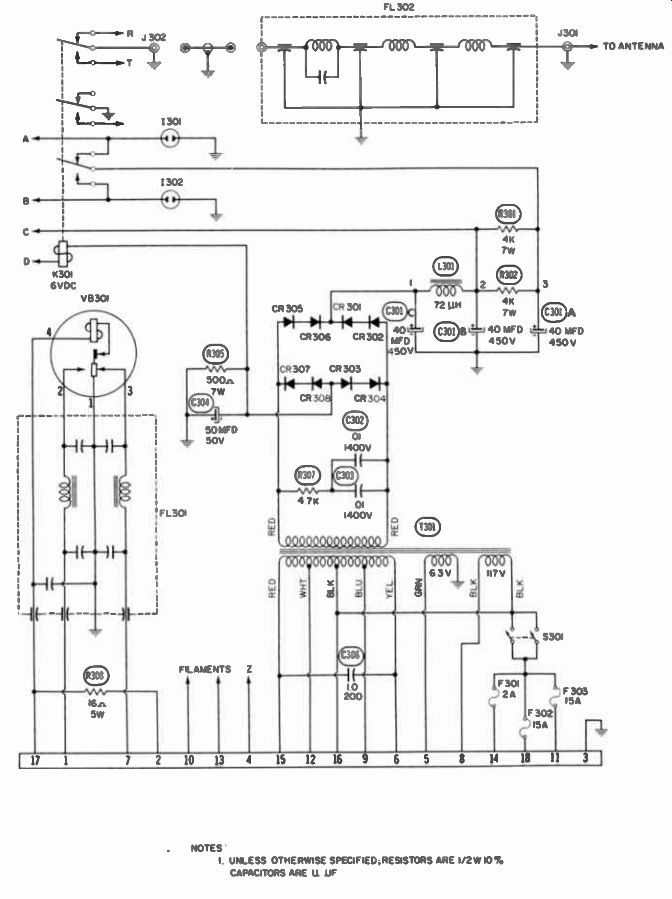
Fig. 4-3. Aerotron "600" series power supply.
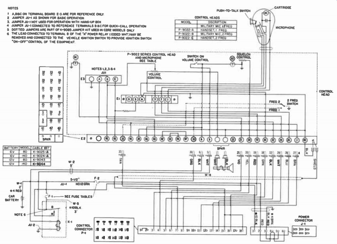
Fig. 4-4
The high-voltage DC output is applied to a filter network consisting of C301A, B, and C, L301, and R301 and 2. Un-keyed high voltage is taken off at point 2 in this filter, and a somewhat lower voltage from point 3. This low B+ output is switched from receiver to transmitter by relay K301A. A small panel mounted neon bulb (1301) glows when the equipment is receiving power, and another lamp (1302) does the same when the transmitter is keyed.
During DC operation the filaments are operated directly from the DC source, while only the crystal oven operates from the 6.3-volt filament winding of the transformer. The filaments are automatically connected for either 6- or 12-volt operation by jumpers in the power-cable plug. The vibrator (VB301) interrupts the DC input at a 115-cycle rate. The alternated DC is then transformed by T301 in the same manner as AC. The power transformer (T301) is designed for 50- to 400 cycle operation so it can be used on almost any commercial power source throughout the world. Where required, a split 115 230-volt primary-winding transformer can be supplied that can be connected for either 115- or 230-volt operation, as de sired. Operation on 6 or 12 volts DC remains identical to that of the standard transformer.
INTERCABLING
Fig. 4-4 shows the intercabling setup of a Motorola dyna motor-type two-way radio. Here only parts of the transmitter, receiver, and power supply are shown, and these only in relation to the control head. Since the power supply (Fig. 4-5) has a high current drain, battery power must be brought into it through a special cable. Another cable connects the trunk mounted radio to the control head mounted on the dashboard, and also to the battery under the hood. Fuses F1 and F2, generally rated at 15 and 30 amps respectively, are connected to the battery. F1 is in the on-off switch line, and F2 is in the dynamotor line.
When the on-off switch in the control head is turned on, relay K1 is energized as battery current flows through it via F1, pin 5 of terminal board E2, the on-off switch, and pin 6 of E2. When this happens, contacts H and B of K1 transfer, thus connecting the battery (through F1) to the radio power supply via pin 1 of power connector J1. The filament line for the entire radio as well as the vibrator takes its power from this source. In this mode, the receiver is now ready to receive and the transmitter to send. Relays K2, K3, and K4 are shown in their normally de-energized (receive) positions.
With an RF signal of the correct frequency on the antenna and with antenna relay K2 in the position shown, the receiver will recognize and reproduce that signal as audio. This signal is fed into the control head and developed across the volume control. From here it goes to terminal board E2 and then to the speaker.
To transmit, the microphone push-to-talk button is de pressed; this connects ground from El, 4 through the push-to talk switch in the microphone, and relay K3 is energized. When the contacts of K3 change positions, the bottom ones complete the circuit from the battery (A+) to dynamotor control relay
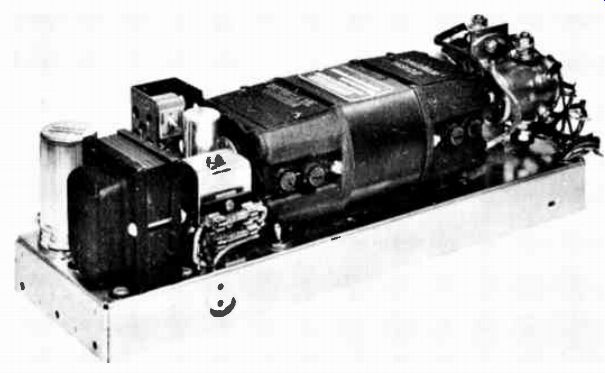
Fig. 4-5. Dynamotor power supply.
K4 and antenna relay K2. Relays K2, K3, and K4 are now energized and will stay that way as long as the microphone button is depressed. The transmitter is now on the air, and when the operator speaks into the microphone, the sound is carried (through the control head) into the speech amplifier in the transmitter.
All other functions are accomplished by use of the control cable. They include control of the receiver squelch; selection of the transmitting channel, by use of the 2 frequency switch in the control head; automatic indication by lamp M1 when the transmitter is on the air; and automatic indication by lamp M2 when the radio is receiving power.