EDITORIAL -- By Edward T. Dell, Jr.
GUEST EDITORIAL -- By Gary Galo
AUDIO AID--Resins for Loads -- By Mark L. Sanfilipo
JUST LOOKING
LETTERS
EDITORIAL
World Markets
From the small-town perspective where your neighbors are few in number, it is rare that we lift our eyes and minds beyond the back fence. Yes, we go to the mall (when absolutely necessary) or to the supermarket or the hardware store (local vs. Home Depot) to do our shop ping. But the world is much more with us these days than ever before.
The daily news is global-whatever the medium. These periodicals are global in both distribution and communication with readers and authors. It is not unusual to feature one or more articles originating from Italy, Brazil, Japan, England, or France.
Telephone rates have plummeted since deregulation, and we find our selves conversing at surprisingly low tariffs with people half the globe away. Our shipping department deals with five companies delivering parcels nearly everywhere. We deal, as a company, with clients, subscribers, customers, and authors in 100 countries.
The most international boundary-less environment is, however, the Internet, with its sites seemingly as numerous as the galaxies, and its e-mail capability speeding communication and information transfer at speeds and with an ease we could scarcely have imagined even ten years ago.
This is not a deep, awestruck bow in the direction of technology; it is rather a call to each of you to begin thinking about your possible connections to the wide world which is open to you.
First of all, I address those of you writing to me surprisingly often looking for parts mentioned in one of our articles.
Those funny transistor numbers with Bs in them are obviously European. American companies have yet to catch on that we live in one world, so they supply only North American or possibly Japanese and Korean ones. Well, the countries of the EU (the European Union, which now has its own currency and looks as though it might become a USE (United States of Europe) very soon, have a very large industrial commerce making lots of interesting electronic parts.
We haven't convinced many of those parts retailers to advertise, but we're trying. If you are worried about currency exchange or import duties, remember that you have a credit card, and an internet connection on your computer.
These days almost all the larger electronics vendors have safe vending practices.
The credit-card business is also so competitive these days that most of the companies protect your purchase so effectively that the caveats really apply to the merchants.
Is there a language barrier in Europe? Not noticeably. Most vendors speak our language much better than we speak theirs.
But this whole-world-commerce question is a two-way opportunity, it seems to me. If you are a company offering your US and Canadian customers a catalog, it is a serious mistake to ignore customers in the UK or in Europe, not to mention the Pacific rim countries. More and more enthusiasts worldwide pay their bills with credit cards, and there are available very efficient and afford able shipping services that can deliver safely and relatively inexpensively.
North American firms have a large ad vantage in terms of a reputation for innovative and quality products, for which customers from other countries are willing to pay.
There are some areas of the world that are still unstable and where transport systems are less than reliable, but it is not difficult to learn which areas those are.
The transport companies are very good at advising vendors about such details.
The reality of our situation as both sellers and buyers in this present time is literally a world market. Until now it has been such a market for the larger merchant bodies of the world. Now it is our turn as individuals and small businesses to buy and sell in the whole world. Of course, there are risks, but those will be managed in time. editor will be considered for publication unless you indicate otherwise. However, submission does not guarantee publication.
Audio Electronics reserves the right to edit your letters or technical queries for length and clarity. Letters should be brief and to the point, you prepare your manuscript submission are available by sending a self-addressed envelope with loose postage. Guidelines are also on our website. We encourage writers to query us before submitting an article. We acknowledge submissions upon receipt, then respond with acceptance or rejection within six weeks. Include a self-addressed envelope and loose stamps for manuscript return.
About this issue
For those of you who are curious, but have yet to take the plunge into the world of tubes, we lead off this issue with an article that may convince you. Generoso Cozza’s hybrid design ("A Hybrid Tube/MOSFET SE Amp," p. 10) retains the benefits of tubes and transistors, while avoiding the pitfalls associated with both worlds.
Designer Eric K. Pritchard re-evaluates his engineering background and experience as he gets in touch with his subjective side in the design of guitar amps ("Is 'Objective' Correct?" p. 12).
Now you can quell the battle in today's living rooms over control of the TV set's volume. Charles Hansen shows you how with the Hearing Assistant (p. 16), an amp that runs off your VCR as a separate audio level control. Establish harmony in the TV room and listening enjoyment for all.
In the fourth part of his series on amp design, Dr. Norman E. Thagard examines the all-important topic of output stage design and the corresponding issues of heat, power, and current ("A Case Study in Audio Amplifier Design: The A40M," p. 20).
If you're in the market for a separate preamp, you are faced with many choices. Marchand's passive preamp is one, which Charles Hansen assembles and tests in one of two kit reviews in this issue (p. 45).
Another kit review (p. 38) tackles a headphone amplifier kit, which provides the headphone user with a quality unit at an affordable price, according to review editor Gary Galo.
We've kept Gary extremely busy for this issue. He takes the wraps off a pro audio CD recorder from British-based HHB Communications ("Product Re view," p. 32). And, finally, Gary shares his impressions of the latest AES convention in New York, where many manufacturers seem to be focused on high-quality sound reproduction ("Guest Editorial," p. 8).
In "Resins for Loads" (Audio Aid, p. 54), Mark L. Sanfilipo illustrates how you can protect your components from breakage by encasing them in a resin mold.
Regular Contributors
Erno Borbely, Charles Hansen, Nelson Pass, Reg Williamson Vice President Karen Hebert Assistant Publisher Dennis Brisson Associate Editor Swain Pratt Managing Editor Judith Griggs
Editorial Assistant
Marianne Conway
Review Editor Gary Galo Graphics Director Tina Hoppock Assistant Graphics Director Diane Luopa Marketing Director Laurel Humphrey Customer Service Kelly Bennett Kim Cloutier Sales Department Jeanne DuVal Director Beverly Poirier Account Manager Laura Tremblay Account Coordinator Nancy Vernazzaro Advertising Coordinator
------
The peculiar evil of silencing the expression of an opinion is, that it is robbing the human race; posterity as well as the existing generation; those who dissent from the opinion, still more than those who hold it.
--JOHN STUART-MILL
--------
Guest Editorial
The High-End at AES By Gary A. Galo The Audio Engineering Society held its 107" convention at the Javits Convention Center in New York City, September 24-27, 1999. Particularly striking was the extremely high quality of the audio demonstrations offered by several manufacturers, which certainly reflected the convention theme "Advancing the Art of Sound." For audiophiles, the AES convention has not traditionally been the event of choice for high-quality sound reproduction. I began attending New York AES conventions over 20 years ago, when they were held at the Waldorf-Astoria Hotel. For many years, I was appalled at the audio demonstrations.
In the late 1970s through the early 1980s, many manufacturers used a particular line of large coaxial "studio monitor" loudspeakers in their demonstration rooms. The colorful horn tweeters in the center of these drivers sounded like bacon frying. I walked out of many sonic sizzlers in those days, unable to bear the screeching treble. Most audiophiles would never tolerate such sound in their living rooms.
I recall Harvey Rosenberg of New York Audio Labs demonstrating in the early 1980s his company's output-transformerless tube amplifiers using 30ips master tapes played on a modified Studer A-80. When I asked Mr. Rosenberg why he was using one of the popular studio monitor loudspeakers to demonstrate high-end amplifiers and source material, he conceded that the AES market was quite different from the audiophile one.
Improved Equipment
In recent years, those grossly inaccurate loudspeakers have become a small minority at AES. Since the early 1980s, the quality of "studio monitor" loudspeakers has improved by several orders of magnitude, with manufacturers such as B&W (whose excellent loudspeakers have gained acceptance in high-end listening rooms and recording studios alike) leading the way. I believe Speaker Builder has also had a significant positive influence on the science of loudspeaker de sign and the desire for higher-accuracy reproduction in professional monitoring applications. Back in the 1980s several SB authors, including Bob Bullock and Joe D'Appolito, regularly presented papers at AES conventions.
The vast improvement in professional studio loudspeakers is only part of the story, at least in my view. What has also been striking at recent AES conventions is the increasing presence of high-end consumer audio equipment, including preamps, amplifiers, and even cables.
The AES made a serious attempt to discredit the high-end in 1991, with the New York convention theme "Audio Fact and Fantasy-Reckoning With the Realities" (see my report in 7AA 1/92, and letters in 3/92).
Yet despite the continued insistence of a large contingent in the AES, many mainstream audio manufacturers aren't buying the view that all amplifiers and cables sound alike. This was most evident in the demonstration rooms of three of the leading manufacturers in the professional audio industry.
Demos
Cirrus Logic demonstrated the Crystal CS4396 D/A converter, capable of up to 192kHz/24-bit performance. A Pioneer DV-525 DVD player was used as a trans port for a 96kHz/24-bit demonstration CD, feeding a CS4396 evaluation proto type board. Bryston's SP-20 preamp and 4B power amplifier fed a pair of PMC LB-1 loudspeakers. Interconnects were Kimber, and the loudspeaker cables were Nordost Blue Heaven. Cirrus Logic's Fred Valenzuela noted that they did not wish to color the superb resolution of the CS$4396 DAC with inferior equipment.
The JVC demonstration room featured their Digital K2 professional clock-jitter suppressor, intended for digital production and mastering applications. All electronics were from Mark Levinson, including the No. 37 CD transport, 36s dig ital processor, 38s preamplifier, and 332 stereo power amp. Madrigal and Harmonics interconnects were used for the low-level connections, along with loudspeaker cables and power cords by MIT.
The loudspeakers were WATT Puppies.
Digital
K2 could also be auditioned with Grado RS-1 headphones powered by a custom-built Holmes-Powell tube amplifier. Only three of these headphone amps exist, selling for around $3,000.
It goes without saying that the improvements rendered by Digital K2 were readily audible on this high-resolution equipment. JVC's representative noted that expensive equipment isn't needed to hear improvements effected by Digital K2, but high-end equipment is necessary to show the maximum performance capabilities of the K2 system.
Sony demonstrated its Super Audio Compact Disc (SACD), a format offering up to six channels of high-definition digital audio, with a sampling rate of 2.8MHz. Their five-channel demonstration was, without a doubt, the finest sound I have ever heard at an AES convention. The loudspeakers were Sony SS MO9ED, designed in the US, manufactured in Park Ridge, NJ, and retailing for around $16,000 per pair. They were powered by Pass X600 Class-A mono amplifiers, and all interconnect and loud speaker cables were manufactured by Straightwire.
The demonstration room was treated with panels made by RRG. Sony's David Kawakami noted that although the superiority of the SACD system will be audible on normal consumer equipment, the high-end equipment used in this demonstration was selected to reveal the full capabilities of the format.
Sony also held a special presentation on the SACD, featuring several distinguished panelists including recording engineer Tom Jung of DMP. Jung's endorsement of SACD was most enthusiastic. He believes that the SACD system yields recordings closer to the direct feed from the mixing console than anything he has previously heard, noting that he has observed greater differences be tween two pieces of cable. No one on the panel blinked, and no one in the large audience attacked Mr. Jung for ex pressing the view that cables sound different from one another.
In writing this editorial, I did not in tend to provoke another heated, and irresolvable, debate on this issue. In deed, these mainstream professional audio manufacturers may have already done so. Despite the concerted efforts of many of its members, the high-end may have found a permanent place in the Audio Engineering Society.
As audio manufacturers develop even more sophisticated digital hard ware, I believe we shall see an even greater proliferation of high-end audio equipment at AES demonstrations, in order to hear these new products in their best light. I find this change most refreshing.
Letters
For Good Measure
You certainly must have heard the European community among your readership rejoicing at the Christmas editorial in AE 6/99 ("Out, Out, Damned Dot," p. 5).
The final acceptance of metrication, late as it is, was just in time to fit into the same millennium as the Declaration of Independence. (But even in the most perfect world, there is always a corner around which the devil lurks. We don't wish to be niggardly and complain that a centi-farad should, in fact, be 10,000uF [and not 100,000, which, in turn, would be a deci-farad]. Europeans are just as lackadaisical when it comes to matters like this and refer to a decimeter as 10 centimeters. And in Eastern Europe people buy 20 decagrams of butter, when 200 grams would have done just as well.) Mr. Dell overlooked one minor point that the Europeans also pride themselves on having introduced to the electronic world: the abolition of the decimal point altogether. Rather than putting 4.7n into a small-print, crammed, circuit diagram, where it is prone to become lost or easily pass unnoticed, we spell it 4n7, with the designation in lieu of the decimal point, and think that is rather neat. Don't you?
Klaus Noll; Koln, Germany
[I fully agree. But I wanted to keep the shock of change to a minimum for this stage. -F Ed.]
Reader Critique
AE 6/99 is a most entertaining and informative issue. I heartily support the move away from unnecessary zeros and decimal points ("Editorial," p. 5). Unfortunately, "nF" is so seldom used that many interpret it as a typo and think it should be "mF," then compounding the error by believing that "microfarad" is intended! Perhaps with increased use of "nF," this will diminish. And at least as a schematic notation, most "mF" occurrences, where milli-farad is truly intended, can be properly read based on context, i.e., when it's a power-supply filter cap. We must convince the cap manufacturers as well, though, as all of the catalogs I've seen persist in the many-digits-of-microfarads approach--as if you're getting more for your money.
Note that there is one error in the middle of the text. Either "...to cF, the centi farad, or 10,000uF" was intended, or "...to dF, the decifarad, or 100,000uF." Ah, the perils of the editor who must edit himself! I found it interesting that JFETSs are so prominent of late, with both Borbely (p. 16) and Thagard (p. 22) among their proponents. I don't really understand why Borbely's series is titled "The New Frontier," however. I read with great excitement hoping to find out about some new and improved parts, but all listed so far are quite old (albeit excellent!). The circuit topologies are not new, save perhaps the author's JFET analog of the White follower. And why not explain the selection criteria for the "cascode" devices in Figs. 14B and 17, and why the input capacitance changes and by how much? But I know space is limited.
Thagard's series reveals a skillful teacher at work and should assist many in understanding its subject. His discussion of the Miller effect is especially good. One quibble: the discussion of the attenuation due to the DC blocking capacitor at the input is wrong and mis leading, implying that we can treat reactive impedance magnitudes as though they were resistances. "If you apply a 1Hz signal to the amplifier input, one half of the signal voltage will drop across the blocking capacitor, so the attenuation is about 50% at 1Hz." It most certainly is not 50%, but is rather only about 3dB down, or about 70.7% of the input, and slightly less by the voltage divider factor of R2/(R1 + R2). Maybe a sidebar with explicit formulas would have been in order.
In the discussion about the input stage current source, I fail to see why the temperature drift is given so much attention (hand-selecting resistors for tempco to match a voltage reference?), as though a small variation were going to significantly affect performance. And then the author turns around and declares the cur rent regulator diode as overkill and suggests a 20k-ohm resistor be used instead- thus limiting the impedance of the composite current source to little more than that resistance! Now variations in the characteristics of the input transistors (both initial and temperature-induced) will change the stage current plenty.
Why not have two independent current sources off each rail? They can be as well-matched as you like and substantially lower-noise as well.
Many modern JFETs, the 2SK170, for example, do not behave in accordance with the square-law equation; the exponent is much larger than two. I once tried to design a quarter-square multiplier using the -170 (selected for its superbly low noise) and found out the hard way! The early Shockley theory, to which many still refer, made certain assumptions about junction doping profiles (uniform) and channel lengths (long).
The anonymous material on capacitor dielectric absorption communicated in "Letters" (p. 48) by Sehring was quite good, if tantalizingly brief. There is substantial literature on the subject from the analog computing days, which it may be time to resurrect. See, for example, Electronic Analog Computers, Korn & Korn, McGraw-Hill, 1956.
Brad Wood Chatsworth, CA
Erno Borbely responds:
I guess Mr. Wood is new to the readership of Audio Electronics (or Audio Amateur, for that matter) if he says, "JFETs are so prominent of late," or else he has not read my articles in the last 15 years. I have been using and promoting JFETs since 1984! And the title "New Frontiers” is coined to indicate that I firmly believe the JFETs allow you to reproduce music in a mo natural way than other active devices.
I am sorry to hear he is disappointed about the contents of the article, because he did no find "new and improved devices" and "ne topologies." As to "new and improved device I am afraid that not much is happening on the JFET market, especially for specific audio use. I fact, many of the "old (albeit excellent)" device are also disappearing from the market. However, if I am mistaken, then I would be happy Mr. Wood would offer his help in this.
Presenting "new topologies" was certain " not the purpose of this basic article. I made a note at the end of Part 2 that I will get down to the more sophisticated topologies in my next installments, but the editor, very wisely, cut this out of my ms.
The lack of explanation of selection criteria for "cascode" devices is partly a matter of limited space, but also a matter of having discussed this in many of my earlier A4/AE articles. But I promise to do it again in my next installment.
Norman Thagard responds:
With regard to the reader's first point, indeed, the impedance of a series RC circuit is the square root of the sum of the squares of the resistance and the capacitive reactance. If the resistance and capacitive reactance are equal, then it follows that the impedance magnitude in this case is (square root of 2) R = 1.414R = 1.414X where X is the capacitive reactance. If Vin is, for example, the maximum value of the sinusoid, then the maximum voltage across the resistor will be [R/(1.414R)] Vin = 0.707Vin.
This is why the attenuation is about 30% when R = X.
The 1Hz output of the high-pass filter formed by the blocking capacitor and R1 + R2 is attenuated by about 30% rather than the 50% that I stated. Since there is some additional loss across R1, attenuation at the amplifier input (gates Q1a and Q2a) is a little more than 30%, but still less than 50%. I state correctly in the last sentence that the response is down 3dB at 1Hz, which is exactly equivalent to saying that there is 30% attenuation at 1Hz. You can, in fact, treat capacitive reactance as though it were a resistance if only an approximate idea of the effect is needed, but I should have elaborated.
To the second point, I actually thought I made it clear that while matching tempcos was possible, it would not have significant effects on performance and was thus unnecessary. The subject was broached only in the context of the tutorial nature of this article. While substituting the 20k resistor for the current diode does lower the impedance of the current source to a little more than 20k, I believed that some readers would have difficulty finding the 1N528 diode, so I provided an alternative solution that did not require me to offer yet another current source design.
As a matter of fact, 20k is a respectable impedance for the current source of the diff amp input stage of a power amplifier with single ended input, since common-mode rejection is not an important consideration. Mr. Borbely simply uses low-valued resistors to bias some of his JFET dual-diff input stages. I tried the 20k resistor for a while and saw no noticeable deterioration in the DC behavior of the amp.
Since noise introduced by the current source is introduced to the diff amp stages in common mode, I suspect that noise is not all that important. The diff amp stage in the A40 is not sym metrical, so I don't wish to overstate the case for rejection of current source noise. In a diff amp using an active load, current source noise is largely rejected even though the output is taken single-ended. In such cases, the current source noise contribution is so small, relatively that it is usually ignored.
In any event, I can hear absolutely no noise at the speakers, so seeking a lower noise alter native, especially if that means doubling the number of current sources, would certainly be overkill.
I do appreciate the comments. There is a lot of material in this multi-part article, and feed back will improve my lectures in the future.
Help Wanted
I am looking for a user's manual (or copy) for a National four-track tape recorder-model RQ194S. Can anybody help? & Suzanne Whyte CCESY Welyondell.com Readers with information about this topic are encouraged to respond directly to the letter writer at the address pro vided.
-Eds.
ASK AE
RIAA Circuit Solution
I have followed your articles in TAA ("A 40W MOSFET Power Amplifier," TAA 2/88, and "A Mostly MOS Preamp," TAA 1/90 and 2/90), drooling over what I read, but realizing that technically it is all are over this retired architect's head. I settled for adapting the phono circuit to my preamp. I have been into audio since t was "high fidelity," but only in recent years have I begun working with solder and parts.
For months I have been trying to build an accurate RIAA stage, only to achieve an accurate curve but not enough gain or enough gain and a very bloated curve. I tried to incorporate your passive/feedback network ("A Mostly MOS Preamp, Part 17) but the results were the same ...a beautiful curve with the stage as shown but not enough gain! When I paralleled another 47 resistor to R16, the curve from 200Hz to 1kHz rises 3 or 4dBs.
Using the formula '2n RC, I arrived at the increase I needed but always at the expense of curve accuracy. My recently finished preamp is passive with Christopher Paul's buffer (TAA 1/88) as a line stage, so I need 38 to 40dB gain.
Obviously, you did not experience this, so it must be something I did or did not do. But what can I do to realize the additional 6 to 8dBs? I have tried resistors down to 1 0-ohm . I am using an op amp for the gain stage and a discrete buffer output. I really wished to go all discrete, but didn't know how to get the necessary gain.
Thanks for your time and trouble.
Larry Campbell; Coral Springs, FL
William Chater responds:
I am gratified that you have found some value in my articles. It is feedback like yours that makes our hobby additionally worthwhile.
If I understood you correctly, you are using an op amp instead of the discrete circuit of Fig.
6 of the article. This would be a circuit like that shown in the article's Fig. 2, with your op amp inserted as the figure's triangular gain block.
Since you don't mention what particulars apply to your circuit, I can only reply in a somewhat general way.
You should see a frequency-flat rise in gain over the whole audio band if you lower the value of R16, as mentioned. But you should not trust lower values of R16 than two paralleled 47 parts. The reason for this is that as in all feedback loops, the overall gain is determined by the relation Net Gain = Loop Gain/[1 + Loop Gain x feedback]
For most uses of such a circuit, be careful to keep the factor [Loop Gain x feedback] well above unity. Thus, the Net Gain is closely equal to the reciprocal of the feedback, as is desired.
I am able to claim that this relationship holds true for the design as in Fig. 6, but per haps it is not true in the case you describe. This would explain why low values of R16 (such as 10 ohm) don't give you what you expect.
The easiest thing for me to suggest, of course, is that you just build the preamp entirely as described in the article, using the passive RIAA parts and the Fig. 7 post-amp version.
(Your op-amp version of Fig. 6 might still be 0K). You would know from the details I have given in the article whether this is compatible with your system.
You can tailor it for gain by the limited gain addition given by setting R16 to its 24 value.
Then, if necessary, you might develop more gain in the Fig. 7 circuit by changing the resistors R188, R191 to provide a final adjustment.
Raising R191 would raise the Fig. 7 gain approximately in proportion to the R191 value, as long as you keep it below about 5k to 10k, so that the Net Gain relation given above is still valid for this circuit too.
Your complete RIAA response will thus be constructed in three parts:
1. Your op-amp version of Fig. 6 using the feed back parts
R14 = 2k, R15 = 19.1k, R16 = 24 or 47 ohm , and C12 = a short circuit
2. the circuit of Fig. 7 with its passive RIAA parts
3. Chris Paul's output buffer.
You may find that there is enough gain with the original parts values in this three-part RIAA circuit. I suggest starting with those values and then tailoring your system as described. -
AUDIO AID
Resins for Loads
Whether you're an equipment building enthusiast or professional, you're likely to have collected bit by piece a mess of components such as caps, resistors, and inductors, that you tend to use over and over again. If so, then you've probably discovered, at the worst possible moment, just how fragile the leads can be. Bend them once too often and away they go! And away you go to the local electronics emporium... if they're open.
I've broken off leads just feeding them into the jaws of alligator clips or, on occasion, just pulling them out of the parts drawer.
The last time that happened to one of my trusty reference resistors, I decided to put an end to this fragile state of affairs and made a quick trip to the local hobbyist store for a supply of casting resin, along with a supply of catalyst.
My plan was to encase the components in what is essentially a small, clear brick (with nothing but the connectors I soldered to the leads prior to potting jut ting out of the brick), effectively protecting the component from further harm.
Once I had the resin and catalyst in hand, all I had to do was find molds into which I could pour the resin. Since the hobby store didn't have anything of suit able size, I used a bunch of old, empty, plastic tack boxes I had on hand. They were the perfect size, and once the casting had cured sufficiently, I simply peeled the boxes away and discarded them. Perfect.
Caveats Before I describe the technique I used, a few caveats are in order. First, unless you're a pro who knows exactly how to use the stuff, thoroughly read and under ...
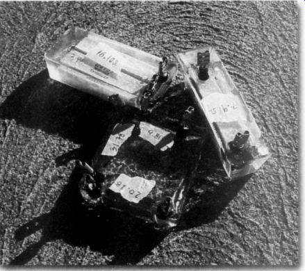
PHOTO 1: Encased components.
...stand the instructions and health warnings you'll no doubt find printed on the resin and catalyst containers.
This stuff gives off a truly ferocious stink until it cures. It smells like airplane glue, but with an intensity akin to that of a skunk smell. So unless you have access to professional casting facilities, perform the casting outdoors. It also wouldn't hurt to stand up-wind of the molds as you pour the resin. When I poured the comparatively small batches required in this case, the resin did such a fine job of stinking up my backyard that even the dumbest mosquitoes had the sense to stay away.
If you've not worked with casting resin before, you might consider making a couple of test pours to get a feel for resin/catalyst mix ratio behavior and curing time. My experience has shown that too much catalyst and the pour will fracture when it hardens; too little and it will take a very long time to cure...if it ever does. Please read the part about ferocious stinks again.
Procedure
To begin the process, calculate the approximate volume of resin you need and pre-mix a fraction of the total in a container separate from the molds.
Then pour a thin layer into each mold and let it cure to the point where it will support the weight of the component.
Once you've poured this thin layer into each mold, mix the remainder of resin you need to com plete the job, place the component in the mold, and complete the pour (Photo 1).
At this point you simply need to wait until the resin cures. If I'm going to label the components, I tend to affix the labels on the exterior of the cured pour:
inks can do strange things-like smudge out, fade, or disappear-when mixed with the resin.
Once your pours have cured, pop your newly armored components out of their molds. They're now ready to use. o + / -
Mark L. Sanfilipo; Ambherst, NY
Just Looking
RICHARDSON OFFERS APT MOSFETS
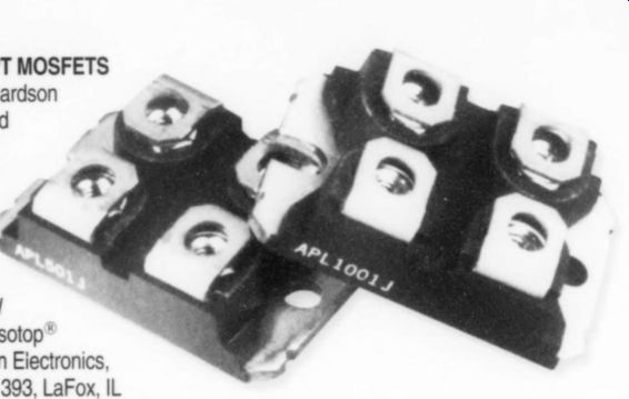
Electric specialty distributor Richardson Electronics now stocks Advanced Power Technology's (APT) new series of high-power MOSFETs, developed specifically for linear applications-the APL501J (the 500V version) and the APL1001J (the 1000V version). Both devices are 570W dissipation parts in the isolated Isotop * (SOT-227) package. Richardson Electronics, 40W267 Keslinger Rd., PO Box 393, LaFox, IL 60147-0393, (630) 208-2200, FAX (630) 208-2550
VIBRATION CONTROL
Bright Star Audio's AirMass DVD decouples sensitive electronic component from external sources of destructive vibration. Performance is improved for bass, dynamics, clarity, smoothness, soundfield, imaging, color saturation black level, skin tones, detail, and more. The multi-layer construction of each model in the Reference Series provides vibration control employing carbon fiber, glass crystal, high-density polymers, MD fiber laminates, and polymer adhesives. Bright Star's new Gemini Isolation Twin combines the Air Mass pneumatic mount with the Big Rock platform into a single vibration control product. It decouples the audio or video component from low frequency floor-borne vibration by virtue of the integral air cell and absorbs chassis resonance in the high-mass sand-filled section. Bright Star Audio, 2363 Teller Rd., Unit 115, Newbury Park, CA 91320, (805) 375-2629, FAX (805) 375-263
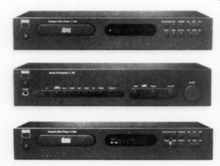
NAD EXPANDS CLASSIC SERIES
Three new products introduced by NAD are the C160 Stereo Preamplifier, the C540, and the C520 CD Players. TheC160 Stereo Preamplifier has gold-plated input/output. connectors, signal switching via gold relays throughout, and an up-rated, gold-element. Alps volume control to maintain optimal signal purity. The C160 also features an improved phono-preamp section with switchable gain for MM or MC cartridges. The C540 CD Player is based on the 24-bit Burr-Brown sigma/delta digital-to-analog converter, the C540 delivers digital accuracy with linearity of -100dB and below. Multiple individual power supplies prevent unwanted interaction between digital and analog circuits. The C520 CD Player duplicates the C540 in basic functions and many technical details, while employing a less costly, 20-bit Burr-Brown converter. The C520 also maintains a separately regulated digital/analog-section power supply, and NAD's jitter-reducing transport and damped-clock technology. NAD Electronics of America, 6 Merchant St., Sharon, MA 02067, (781) 784-8586, FAX (781) 784-8386.
MARSH SOUND DESIGN
After 30 years of designing High-End audio systems (from preamps to speakers) and consulting for other companies, Richard Marsh is starting his own firm, Marsh Sound Design. The company will develop consumer electronics representing the distillation of his years of experience and research in audio.
Author, lecturer, engineer, and inventor, Marsh has written extensively for AE/TAA over the years. He also designed the MIT Z Systems powerline components and a series of power products for Monster Cable. He holds patents in powerline concepts, capacitor design (the well-regarded Multi-Cap, for example), connectors, and other audio-related products. Some of the audio products that are now available include: tube-hybrid line amplifier, MSD P2000t; solid-state line amplifier, P2000 (with remote); 400W stereo power amplifier, A400s; and 200W stereo power amplifier, A200s. Marsh Sound Design, 62 EI Camino Dr., Corte Madera, CA 94925, (415) 927-4672, FAX (415) 924-6846.
CONTEMPORARY HOME THEATER
The award-winning company, European Design in Scottsdale, Arizona, has specialized for more than 10 years in designing and crafting audio/video home-theater cabinetry worthy of today's highest-end electronics. The original design is achieved by working directly with architects, interior designers, audio and visual equipment suppliers, and homeowners, to create one-of-a-kind units that dramatically reflect the personality of the owner and the home. Owner Allan Rosenthal, a third generation woodworker, and his staff personally designs each piece using a mix of exotic veneers and woods, glass, metal, lighting, cables, and unique hardware to create furniture with the look of contemporary sculpture. European Design, 7655 East Redfield Rd., Suite One, Scottsdale, AZ 85260, (480) 951-5234, FAX (480) 951-5233.
ADs
DanisH Audio ConnecT CT1 and CT2 Audio Attenuators
= State of the art audio volume control for hi-fi, AV and pro-audio
= For upgrading existing audio equipment and as passive preamp
* Wide bandwidth, low distortion, high accuracy, long lifetime
= Available in 10, 20, 50, 100, 250 and 500 kOhm
» Matching audio input selector switch (CT3) available
= Various accessories available (knobs etc.)

The secret In DACT attenuators the signal is kept "clean" because we take special care of the signal path.
Our motto is: "The shorter the better". We use non inductive, low noise, metal film Surface Mount resistors. Compared to leaded resistors our SM resistors have a much shorter signal path (typical 5 times shorter) and much lower series inductance.
Rear view of the CT2 PCB containing the SM resistor network (the PCB diameter is 1").
FROM TOP: CT1 mono, CT1 stereo, CT1 balanced stereo (4 decks), CT2 stereo CT2 6 channel AV.
CT100 Stereo Phono Stage / RIAA Preamplifier Module.
US/Canada distribution Aloha Audio P.O. Box 30083, Honolulu, Hawaii 96820, USA
Using the SM resistors allows us to design compact PCB's with a very short signal path. To make sure of the long-term quality of the signal path we gold plate it. All PCB traces, connectors and switch contacts and wipers are plated with hard-gold. The mechanical parts of he switches are precision made in Switzerland.
CT1/CT2 key specifications Number of steps Ea i Bandwidth (10 kOhm)
Attenuation accuracy
Channel matching Mechanical life, min.
CT101
Line Stage Module
FEATURES
= High output drive capability ( + / - 14V / + / - 25mA)
* Drives long cables (output resistance 0.1 ohm)
* Dual-mono design (two power supplies)
= Customer selectable gain 0, 6 or 12dB
= Wide power supply range (+5V to +100V)
CT100
Phono Stage Module
FEATURES http://www.aloha-audio.com Very accurate RIAA equalization Wide selection of gain and input imp. settings For MM and MC without set-up transformer Dual-mono design (two power supplies required) Balanced output option built-in DACT preamplifier modules Our preamplifier modules are based on the latest component technology available. Most of the active and passive components in the signal path are Surface Mount types. By using SM components and by selecting only the best parts in general we obtain larger bandwidth, and very compact designs. All in favor of the sonic performance. PCB traces, contacts and connectors on CT100 and CT101 are gold plated. Sonically CT100 and CT101 are characterized by high accuracy and linearity and lots of details and dynamics.
CT101 Two-channel Linear Preamplifier Module with a stereo CT1 attenuator mounted (the attenuator is not included when purchasing a CT101)
Manufacturer Danish Audio ConnecT Ltd. Rm. 1501/3 Ban Chang Glas Haus Bldg 1 Sukhumvit Road Soi 25, Bangkok 10110, Thailand
MADE IN DENMARK
www. DACT.com
-------------
IS ELECTRONICS AND/OR COMPUTER TECHNO YOUR PROFESSION OR HOBBY?
If so, Elektor Electronics is just the magazine for you! Since 1977, it has been publishing construction projects at professional level as well as informative articles about the developing world of electronics and computers.
The world of electronics is in constant flux.
What is new today may be obsolescent in a very short time. Of course, the basics do not change, but applications do. Elektor Electronics is quick to respond to the changing face of electronics and to adapt itself to the varying needs of its readers.
It contains fairly easy as well as more complex construction projects on a wide variety of electronics subjects, from audio & hi-fi through computers and microprocessors to test and measuring instruments.
Moreover, each issue contains a FREE 16-page supplement dealing with one subject only, such as Microcontrollers, Audio & Hi-fi, Test & Measurement, Computers, and others.
------------------
Origin Live
UPGRADE YOUR TURNTABLE
TURBOCHARGING YOUR REGA ARM
"The single most important upgrade you can ever make to any record deck concerns the motor drive. Nothing can compare you for the shock of going DC, in a word Gobsmacking" COMMON GROUNDMAGAZINE
Whether you own a Linn Lingo or a Rega, the results of upgrading to the Origin Live dc motor and power supply are simply astounding. This high grade motor kit is designed as a drop in replacement for almost all turntable motors. Decks benefiting so far from this ultimate of upgrades include Linn, Roksan, Michell, System deck, Rock etc. With a 6 Volt power supply it is safe and easy to fit. Guidance instructions are provided. At $345 (add $35 for fully soldered and tested regulator board) with money back guarantee this is a bargain out of all proportion to it's value in terms of performance.
"nothing less than total dynamite"
HI Fl WORLD FEB 99 If you are the proud owner of one of these two arms why not utterly trans form it into the league of super arms with the Origin live structural modification:- $120 inc post & packing. This modification will enable your Rega to perform at a level exceeding that of arms costing over $2000. Internal rewiring with high grade litz cable is also offered at an additional $115 and external rewiring is $115.
I have to say the Rega modifications turn this humble arm into a real Giant killer. Gone is the rather grey, sterile sound of the cooking Rega. Instead, tonal colour is fresh, dynamics have great speed and impact, and the sound stage is huge" HI FI WORLD SUPPLEMENT NOV 97 (structural modification only to a RB250) WHAT HI-FI Sept 98 gave this modification a 5 star rating.
For arm modifications we normally return your arm in 2 - 3 days HIGH TENSILE THIN BOLT \
\ COUNTERWEIGHT RIGID ATTACHMENT BY BOLT ADJUSTMENT
For further information contact:
Origin live, 87 Chessel Crescent, Bitterne, Southampton S019 4BT
Tel: +44 (0) 2380 578877 / 442183
Also see: