This author's unusual amp design features only one discrete component without altering the signal.
The Power Follower 99 may seem a common circuit (Figs. 1 and 2), but it is very different from any other similar design, thus making it unique. It is a typical source follower (an emitter follower, but with a MOSFET working purely in Class A with a current generator. Because it works only in Class A, it requires a bias current sufficient for the selected output power. The current generator is coupled with a DC feedback through a BD139 to prevent any thermal effect (avalanche) on quiescent current.
Significant Features
The first feature that makes a difference in the sonic results is the negative power supply and the signal ground tied to the drain of the source follower. This layout achieves:
- the dis-coupling of the signal current from the power supply, because the current generator has a huge impedance (open, in theory);
- the constant-current flow from the power supply during the music peaks prevents stressing the power supply;
- the symmetric distribution of the power dissipated under static and dynamic conditions, both on the current generator and the source follower, so I have used the same type of devices: all are IRFP150s.
The second feature of note is in the power-supply design. In a capacitive input power supply where a diode bridge is connected to a big capacitor, very high current peaks are produced in the diodes, generating residuals all over the amplifier power band. Therefore, this circuit uses a little capacitor after the bridge. I computed the value of this component with a precise analysis and simulation made with SPICE3f4 (electrical simulation software for UNIX).
This stage is followed by a MOSFET voltage regulator featuring a very low-frequency RC filter (220uF/100k-Ohm) based on the Virtual Battery Operation invented by Technics.
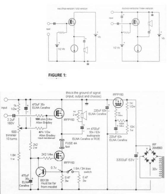
FIGURE 1: The simplified schematic; left: old version; right: new version.
The components used in this stage have also been simulated and optimized for a 3A quiescent current with a capacitor value of 3300uF.
After the regulator there is a capacitor that may seem ridiculously small, but actually it's sufficient because it should not support any current-peak demand. In any situation, the current requested by the amplifier is constant. The component layout is shown in Figs. 3 and 4 and in Photo 1. Figure 5 depicts the circuit board, and Table 1 is the parts list.
Precision Trimming
You should set the 500 ohm precision trimmer to balance the output-fuse voltage to half of the regulator output. You could do this single trim after the switch-on, be cause it just optimizes the output swing to the maximum available. The quiescent current is set by the resistance on the current-generator source pin, but you can change it with the simple formula:
Iq =0.7/R, where 0.7 is the BD139 Vbe.
FIGURE 1: The simplified schematic; left: old version; right: new version.
FIGURE 2: The complete schematic.
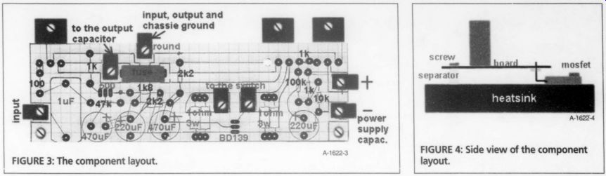
FIGURE 3: The component layout.
FIGURE 4
--------------
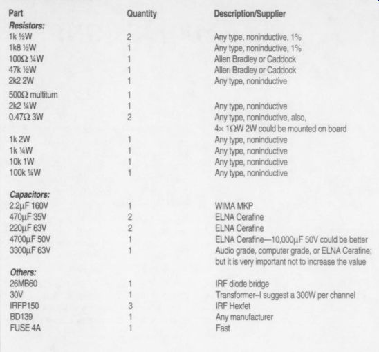
TABLE 1: PARTS LIST
Part Quantity | Description/Supplier
Resistors:
1k 1.W 2
Any type, noninductive, 1% 1k812W 1
Any type, noninductive, 1% poo. de2g : pes ad 4 pa.
240 IW g
Any type, noninductive S000milan ' 242 1uW 1
Any type, non-inducive
047 ohm 3W 2
Any type, noninductive. also.
4x 1 W 2W could be mounted on board 1k2W 1
Any type, noninductive Tk "WwW 1
Any type, noninductive 10k TW 1
Any type, noninductive hogan ' ARPIPS: Bihive
2.2uF 160V 1 WIMA MKP 470uF 35V 2
ELNA Cerafine
220uF 63V 2
ELNA Cerafine 4700uF 50V 1
ELNA Cerafine-10,000uF 50V could be better 3300uF 63V 1
Audio grade, computer grade, or ELNA Cerafine;
al but it is very important not to increase the value
a 300W per channel IRFP150 3 IRF Hexfet BD139 1
Any manufacturer
FUSE 4A 1 Fast
----------------
I have implemented an on-board connection for a switch to modify the bias current (two values) because-since sometimes listen to music with a low SPL- this way I can save power dissipation.
You can use the power-supply transformer with different voltages and currents, from 24V to 33V, but with 250VA minimum per channel; otherwise, you must reduce the bias current. With a bias current of 3A, you can get about 30W RMS at a 6-ohm load.
You can increase the power just by changing the bias and size of the heatsink, because the components are able to manage more power. Since this is a single-ended Class A, the theoretical efficiency is 25% with 100W of dissipated power, so you have only 25W available to the load.
I have implemented this circuit in a standard rack with heatsinks at the side (Fig. 4 and Photo 2) having dimensions of 30 x 42 x 12cm. I would suggest in creasing its dimensions to 30 x 42 x 16cm, or choosing a different mechanical layout, such as a forced-air-flow tunnel.
Note my preference for ELNA Cerafine capacitors, which I like a lot. 1 would say that the MKP/paper-in-oil input cap, the input bypass (470uF), and the output cap are significant for the sound quality. Concerning the others, Roe, Sprague, Mallory, or Siemens computer grade are acceptable.
Concerning the output capacitor, it is important to understand that this component is necessary, and does not worsen the device quality. Note that a dual rail with a push-pull output stage does not solve the problem.
No-Gain Topology
The topology I present has no gain (actually it loses something). It should be pre ceded by a voltage gain stage, with an output swing not lower than 10V RMS and an R less than 1,000-ohm. The input impedance is 47k-ohm/1450pF; you can ad just its resistive value through a fairly wide range just by using a different input resistance. The input capacitance, 1450pF, seems to be very high. Note that a gain stage with a 1,000-ohm output resistance gives a cutoff frequency greater than 100kHz.
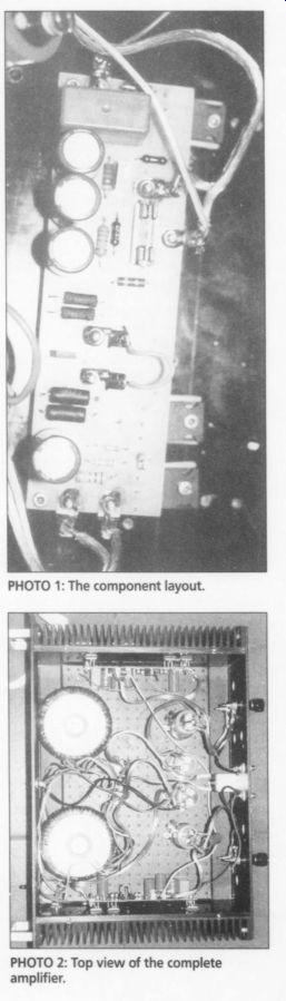
PHOTO 1; PHOTO 2: Top view of the complete amplifier.
My current setup is a vacuum-state preamplifier, made by an SE 5842 resistive load followed by an E182CC connected as a cathode follower able also to drive a Sennheiser 580 headphone. The output device, IRFP1 50, may be replaced by TO3 equivalents with a minimal impact, or by other similar MOSFETs such as IRF250, IRFP250, IRF240, or IRFP240.
It is possible to wire the circuit with out a PCB. In order to reduce the circuit complexity in this kind of implementation, it is possible to leave out the regulator, which obviously increases the filter capacitor from 3,300uF to a minimum of 22mF.
Acknowledgements
Thanks to Nelson Pass and Electronics World mag.
Class A configuration; to Elmar Tielke (Dortmund, Germany), who made me aware that my first version of the amplifier was not taking a constant current from the power supply; and to Francesco Pintavalle, for his sup port on theoretical aspects and for discussing and designing audio circuits with me every day for many years .
Also see: