Just Looking
NEW CATALOGS: For your electronic parts and supplies, "3.4 be sure to check out two recently released electronics catalogs from All Electronics (800-826-5432, FAX 818-781-2653, www.allelectronics.com) and Mouser (800-346-6873, E-mail sales@mouser.com, www.mouser.com).
DC Power Supply: These benchtop units feature a front-panel-mounted precision analog voltmeter and ammeter. Other front-panel indicators and controls include an off/on power switch, a power LED, overload indicator light, and voltage adjustment knob. In addition to constant voltage/current operation and excellent line and load regulation, the system features low ripple and noise characteristics.
B&K Precision, 1031 Segovia Circle, Placentia, CA 92870-7137, (714) 237-9220, FAX (714) 237-9214, website bkprecision.com.
X-CONNECT: Now you can control the input gain of your home-audio or home-theater amplifier level with X-Connect. The latest version has no ground-loop isolator, which makes it suitable for most home-audio applications, especially when you add a subwoofer or center-channel amplifier and you wish to match the gain with the "other" system components. The unit operates from 0 to 50V RMS and has gold RCA inputs and outputs. It is also available with ground loop isolation. Harrison Labs, Inc., 303-841-5360, Harrison_Labs.INC@prodigy.net.
NEWS BRIEFS: The 109 AES convention will take place Sept. 22-25, 2000, at the Los Angeles Convention Center. For more information, contact AES, 60 E. 42" St., Rm. 2520, New York, NY 10165, 212-661 8528, FAX 212-682-0477, E-mail HQ@aes.org, http:/www.aes.org.
DIGITAL FOR CASSETTE PLAYERS: SmartDisk Corporation has developed a prototype of a technology that will extend digital music to users of traditional audio cassette players. Flash Trax resembles a conventional audiocassette, but has a slot that accepts a removable flash memory card on which digital audio files are stored. FlashTrax will enable traditional audio cassette players to play music downloaded from the Internet or copied from an existing CD collection. For more information, go to www.smartdisk.com.
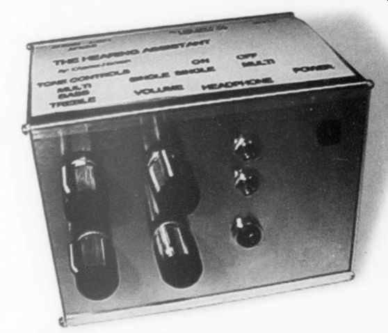
TV HEARING ASSISTANT: The hearing assistant is specifically designed to allow the hearing impaired to enjoy TV. This amp runs off your VCR as a separate audio level control, so volume is totally independent of the TV's setting. The hearing impaired can adjust it to their requirements. This unit is based on an article by Charles Hansen in AE 2/00 (p. 16). The box and PCB (not sold separately) are available for $15 from Sescom, 2100 Ward Drive, Henderson, NV 89015 4249, 800-634-3457, FAX 702-565-4828, E-mail sescom@sescom.com.
IW B2 SPICE A/D 2000: Beige Bag Software has announced B^2 Spice A/D 2000. It includes all the major features required to design and simulate analog, digital, and mixed-mode circuits. B< Spice's simulation engine is based on the industry standard and proven Berkeley Spice and includes many extensions from Xspice. It performs 14 types of analysis, including transient, Fourier, noise. distortion, Monte Carlo, and parameter sweeps. B-Spice provides data-visualization tools for making sense of digital and analog simulations results. It has a schematic editor that allows you to enter and edit circuit designs and set up for simulations. Now you can zoom, scroll, and customize the plots. B Spice AD 2000 runs in Microsoft Windows 95/98/NT. For further information contact Beige Bag Software, 279 E. Liberty, Ann Arbor, MI 48104, (734) 332-0487,website www.beigebag.com.
ABOUT THIS ISSUE
Never one to let a good piece of electronic gear go to waste, Charles Hansen makes use of an abandoned meter to develop a nice piece of test equipment. With a little tweaking, this power meter also doubles as an RMS voltmeter ("Audio Power Meter," p. 6).
Many factors go into good tonearm design. In the first of a two-part series that debunks many of the myths surrounding tonearm behavior, Dick Pierce explores some of the basic physical mechanics of tonearms. Part one examines general principles and static balance (p. 18).
Italian engineer Andrea Ciuffoli presents an unusual amp project with several unique features. See how this Class A MOSFET circuit design, which he calls the Power Follower 99, works (p. 29).
Former astronaut, MD, and college professor, Norman E. Thagard continues his tutorial on designing the A40M 40W/channel MOSFET amp. Part 5 focuses on the power supply ("A Case Study in Audio Amp Design," p. 28).
We have a trio of product reviews featured in this issue. First up is review editor Gary Galo, who tackles the NAD PP-1 Phono Preamplifier. If you need a phono section for your audio setup, you may choose to consider this simple phono preamp that will let you play your collection of LPs (p. 38).
Charles Hansen begins a look at three digital-storage oscilloscopes and critiques the flexibility and convenience of these digital devices (p. 42).
He then introduces us to the family of single in-line PC boards (SIPs) available from Sescom (p. 45).
If you're looking for some interesting electronic designs and applications, be sure to check out Charles Hansen's review of Elektor's book series containing circuits to cover all your audio needs and more ("Book Review," p. 5D).
Finally, veteran broadcast engineer Bill Ruck shares his knowledge of VU meters in this issue's "Audio Aid," p. 54.
IN MEMORIAM
We regret to report Franklin Miller's death early Tuesday, April 25, 2000. He was 56.
Frank was the founder and president of SESCOM electronic products based in Henderson, Nevada, a suburb of Las Vegas. His company produced a wide variety of products for many segments of the audio industry, including broadcast, recording, and ham radio, as well as the do-it-yourself enthusiast. He is survived by his wife Brenda and a son David. The family requests that any memorial donations be sent to The American Diabetes Association.
The peculiar evil of silencing the expression of an opinion is, that it is robbing the human race; posterity as well as the existing generation; those who dissent from the opinion, still more than those who hold it. -- JOHN STUARTMILL
Audio Aids--VU's
Just because the scale reads "VU" does not mean that the meter meets the specific requirements to be a true ANSI standard VU meter.

Also, a true ANSI VU meter must be properly connected with a 3900 ohm source impedance as designed. In the old days, this was a 3600€ resistor in series with a terminated 600 ohm source (300 ohm source impedance). This will give 0 VU = +4dBm. If you desired another "0," you inserted a 3900 ohm pad in series with the meter (i.e. 4dB pad for +8dBm = 0 VU). See my article "More on Mixers and Mike Preamps" in Audio Electronics 3/98 for more details.
Sources
The best true ANSI VU meters are West on and Sifam. You can purchase Weston meters through Allied (800-433-5100, www.allied.avnet.com) or Newark (800 463-9275, newark.com). You can get Sifam meters from Selco Products (800 25-SELCO). (Note: Sifam "Presentor" meters are not ANSI VU meters, including their "retro styled" black-case meter.) Simpson VU meters function pretty well. They are available through any Simpson dealer, Allied, Newark, or just about any good industrial source.
API meters are either bad ANSI meters or not even close...especially the inexpensive back-lit ones. But they look cool in a dark room. Ampex A-440 meters are not ANSI VU meters.
Remember that an ANSI VU meter is an average responding meter that deliberately ignores peaks. I have (some where) the paper from the late '40s that developed the standard. The big net works concluded that you needed only 10dB peak level about "0 UV." That is why all transmission systems today clip at +18dBm (10dB above +8dBm/0VU).
Bill Ruck
San Francisco, CA
Letters
OP AMP IMPROVEMENTS
I have been unable to find the information I need in previous issues of Audio Electronics (or The Audio Amateur). My 24dB/octave Linkwitz/Riley crossover uses TLO74 (quad) and TLO72 (dual) ICs.
I am seeking a pin-for-pin replacement with improved characteristics. Would the AD713 suffice, or is there another IC anyone would recommend? Same question with respect to theMC33078.
Frank S. Thomas iii; Ballwin, MO
Walt Jung Responds:
Mr. Thomas raises a most interesting question regarding the upgrading of older audio circuitry with pin-for-pin improvements, because there are lots of such op amps around. Moreover, if one is willing to expand horizons a bit, lots more can be done beyond basic chip-swapping.
First, to answer the question of whether the AD713 will sub for the TLO74 (or the AD712 for the TLO72), the answer is yes, they certainly will. It is worth noting that the AD711, AD712 and AD713 data sheets all have active filter application examples. All of these parts have FET inputs, and are generally comparable in terms of speed and noise. The MC33079 (quad) and 33078 (dual) family are also pin-for-pin substitutes, but offer lower noise and greater band width, vis-a-vis the FET devices. Offering generally comparable performance to the MC33078 is the OP275 from ADI. Whether or not the lower noise/higher bandwidth of these devices would be a big advantage in your crossover I can't say, since the answer depends upon the impedances around it and the gain of the circuit. Both the MC and OP devices are different from the FET devices mentioned, employing bipolar transistor front ends. While this affords lower noise (which may be seen after their substitution), the higher bias current could be a possible disadvantage with high circuit impedances.
A FET family I have had good audio success with over the last few years is the AD823 dual op amp (a similar topology is also found in the AD824 quad). These are FET input devices, built on a complementary IC process. This means their bipolar NPN and PNP transistors have comparable speeds and gains for greater op amp linearity, a factor not present with the earlier FET parts.
Not to dampen your upgrade parade, but there are some important basic points that should be made about multiple IC audio op amp devices. Because of basic-package power limitations, manufacturers are forced to cut back on the available power from a given op amp in such a multiple package, versus that of a single part. Thus while quads (and duals to a lesser extent) offer great circuit density, they will lag somewhat in all-out performance (particularly with regard to drive) compared to a comparable-circuit single IC. Also, crosstalk between channels simply doesn't exist in single devices, but it is possible with multiples. This depends upon the devices of course, plus the loading. So, while you could replace say your TLO74s with a pair of OP275s, you'd be even better off with 4 OP176s (OP275-type single op amp). I'll leave it to you to decide if you want to kludge up 4 single DIP ICs on a 14-pin header.
If all of that sounds pessimistic, you can hedge your bets on what stages of your filters to go all-out, perhaps using the gutsiest chips for the line-out spots. Worthwhile here is the AD817 single (or AD826 dual) with typical output currents of about 100mA, and ability to drive capacitive loads (such as interconnects) without instability.
You might also investigate on the web audio upgrade companies, some of which offer plug-in DIP IC compatible modules. One such company is LC Audio, offering dual modules adapting the SOIC-only AD825 to standard DIP foot prints (lcaudio.com/ad825.htm). I can't say whether their "Type 1" dual-module will work in your filters, not having seen one first-hand. But, I can heartily do so for the AD825 op amp itself. This single FET input IC is a worthwhile improvement over many op amps for audio. Some of the engineering reasons behind its unique-for-audio virtues are discussed in reference 3 below. If you can over come the physical problems of adapting it into a DIP-style footprint, I suspect you'll find it worth investigating.
Of course, audiophiles will always continue to swap op amps and just listen to their results, and personal favorites will emerge. In spite of that fact, I feel strongly that other environment related factors can sometimes make as much difference to bottom-line performance as the actual IC device. Given that, such things as op-amp output drive/load linearity and system power-supply regulation should be considered whenever possible, if the very best results are sought. While you may not be able to relay out your present circuit board for fully buffered op amp stages, you might consider such, on the next go-round. Right now you might also consider using the best possible power supply regulators on your crossover, since this is more likely to be physically possible.
Given all of the above, my personal choice for an active filter, Sallen-Key suitable op-amp topology actually turns out to be a composite amplifier. This is a circuit functionally equivalent to one op amp, actually employing two physically separate ICs, each optimally selected for its input or output task. By definition, this technique eliminates the thermal distortion effects which plague many single ICs when loaded heavily (even some of those often touted for audio). The design I'm using currently has a fast FET input IC as a linear "front-end," followed by a very high current-output, current: feedback type op amp as an output stage. This stage runs at unity gain, with the ability to drive various loads without impacting distortion. It is an evolution of the AD744/AD811 composite I described in 744 2/92, in "High Performance Audio Stages Using Transimpedance Amplifiers." The whole thing works great for me, but unfortunately, it is likely to be of little help to anyone looking for a simple drop-in dual or quad op-amp replacement.
As further background on this topic, I did a series of Electronic Design articles on audio circuit improvement related to applying op amps effectively, which can be found at the URLs listed below. Various distortions, buffering tricks, and composite amp designs are part of the discussions. Good luck with the crossover up grades, and I trust you'll have better sound in the end!
Walt Jung , Analog Devices
Walt's audio op amp improvement series:
#1 is https://devel.penton.com/ed/Pages magpages/sept0198/tt/0901tt.htm
#2 is https://devel.penton.com/ed/Pages/ magpages/oct0198/tt/1001tt.htm
#3 is https://devel.penton.com/ed/Pages magpages/dec0198/tt/1201tt.htm
#4 is https://devel.penton.com/ed/Pages magpages/dec1498/tt/1214tt. htm
TIMELY
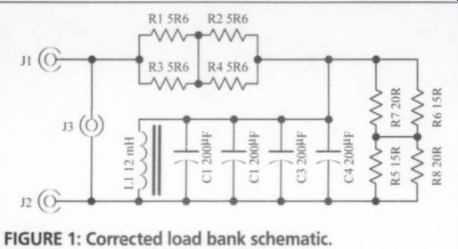
FIGURE 1: Corrected load bank schematic.
I read with interest Erland Unruh's test of the Superclock (AE 6/99, p. 42). I appreciated it for several reasons: his tests used "normal" equipment, not some esoteric gear no body else has. He refrained from making absolute statements, but clearly indicated the limits on the tests. This made it much more trustworthy, in contrast with some re- views that give the impression the reviewer has exclusive access to the truth.
Yes, he was opinionated, but aren't we all, including the manufacturer.
There was no indication that Erland'spersonal opinion influenced his final conclusions. All in all, this was a review that relates very well to the average audiophile and his resources.
In contrast, I was disappointed with the reaction of the manufacturer. If you need to resort to stating that a trimmer cap is not a variable cap, you apparently have nothing of substance to report. If the manufacturer had evidence to the contrary of Erland's findings, why didn't he say so? Yes, the outcome of Erland's experiments were not conclusive, but they were certainly helpful. The review did, at least to this reader, provide a lot of useful information. I hope to see more re views of this type. Well done, Erland! Jan Didden Hoensbroek, Netherlands Erland Unruh responds:
I would like to thank Jan Didden for his positive feedback on the review. I agree 100% with the comments and also hope to see more of these types of investigating reviews. With some luck we can also look forward to more constructive response from manufacturers. Even if the response wasn't constructive this time, it was quite revealing.
CORRECTED LOAD
There is an error in Fig. 5 of Charles Hansen's "Passive Loads for Audio Testing" (AE 1/00, p. 37). The line from R2/R4 should connect to the other side of the capacitor bank as shown in Fig. 1.
Fred Gloeckler Woodbridge, VA LPTOCD I don't know whether what I am trying to do is actually possible. I wish to record an old vinyl LP to CD from the headphone socket on my hi-fi into my PC as a wave file via the line input on my sound card.
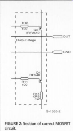
FIGURE 2: Section of correct MOSFET circuit.
So far I have had no joy, as every time I try to record there appears to be too much power (not volume). Is there a modification I can make to the lead to re duce this power output? I realize that the best way would be to use a "line out" from a hi-fi, but unfortunately my hi-fi does not have a line out.
Dave Cass; Ipswich IP1 2H Q UK
Charles Hansen responds:
The headphone output is not a very good place to tap a signal, especially from consumer audio gear. The headphone output of most consumer receivers is simply a power resistor in series with the speaker terminals. Since you are at the end of the amplification chain, the noise level and distortion are at their highest.
As you have noted, the signal level is also very high, with too much voltage that will over load the analog input of your sound card. With only 1W of output power into 8C2, the voltage to the sound card will be 2.83V RMS. The maximum specified output (0dB) from a CD player is 2V RMS.
Your receiver should have a line-level output at its tape monitor loop. Look for TAPE OUT or TAPE REC output jacks, which have a lower signal level of 250-500mV at rated sensitivity, and should prove compatible with your compute sound card's line input. The tape loop signal is fixed and independent of the receiver's volume control setting. If the level is still too high, you can insert a dual 10k audio volume control such as the Mouser 313-2420-10K, between the receiver and sound card.
My other concern is the quality of your phono section. Most consumer receivers use a single op amp for the phono preamp, which is usually a highly compromised design. If you plan to transfer a lot of vinyl to audio CDs, you may choose to consider building a dedicate phono preamp unit. Many excellent designs have been published in Audio Electronics and The Audio Amateur over the years. If you are making transfers to rip to MP3 however, your receiver's phono circuit may be good enough.
UPDATE
In reading my article, "A Hybrid Tube/MOSFET SE Amp," AE 2/00, 1 found a small but important error. In the amplifier schematic, (Fig. 2, p. 10), the collector and emitter of Q1 and Q2 are interchanged. In both Q1 and Q2 transistors, the arrow must go from up to down (see Fig. 2).
Generoso Cozza Banchette, Italy
FEEDBACK
I have very much enjoyed the three articles on audio power amplifier distortion by Douglas Self (AE 2-4/99). Mr. Self obviously has a tremendous depth of knowledge and keen insight on this topic. I was particularly interested in his treatment of the feedback blocking capacitor in Part 3 of the series. Would Mr. Self please comment on the alternative method of dealing with this capacitor published in "On Power Amplifier Feed back Networks" (TAA 1/96, p. 12)?
Richard Guest; Toronto, Canada
Douglas Self responds:
The alternative feedback scheme certainly appears to be workable; at any rate it works in SPICE simulation, though I have not tried it for real. However, I found that to get a suitably low LF rolloff with typical resistor values, the capacitor was 10pF, which still means an electrolytic, though a physically smaller one. I am not sure this gets us much further forward.
MISLEADING
I have a complaint, a pet peeve of mine.
Several of your authors are perpetuating the misinformation that the common mode gain of a differential amplifier is proportional to the ratio of the load resistor to the tail resistor. I have seen this same misinformation stated in text books. If this were correct, then to obtain zero common-mode gain, or, equivalently, infinite common-mode rejection, either the load resistor must be zero or the tail resistor must be infinite. This is, of course, impractical and also incorrect.
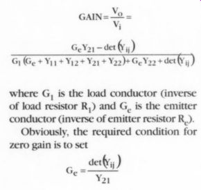
Using Y-parameter notation, the gain of an amplifier is given by the following formula:
V, GAIN=-2= Vi GY) - det \) Gy (Ge + Y11 + Yi2+ Y21 + Y22 + GYap + det {Yi
where G, is the load conductor (inverse of load resistor R)) and G,, is the emitter conductor (inverse of emitter resistor R).
Obviously, the required condition for zero gain is to set Je Y2) in the numerator. Notice that this is a null type of condition and for values of G, larger or smaller than this value, the gain increases from zero. Also note that the value of G, is immaterial.
When converted to common emitter H parameters, the condition for zero gain turns out to be G, = H,,/H,, or equivalently, R.=R xB. R is the transistor output resistance and J is the transistor current gain.
For a small signal transistor at 1mA collector current, R is on the order of 100k ohm, and B is on the order of 100. The emitter resistor R,. is then on the order of 10M, large but definitely not infinite (Fig. 3).
We Want Your Feedback!
Audio Electronics encourages reader feedback in the form of letters, queries, and comments.
Audio Electronics reserves the right to edit letters for length and Re or Ge
Your authors are using the approximation that the gain of an amplifier equals the ratio of the load resistor to the unby passed emitter resistor. According to the approximation, the gain of an amplifier is given by this formula
GAIN="Yo _ RL _ GE Vi Bg GG
which is obviously incorrect when compared to the exact formula above. This approximation fails to account for the fact that the emitter or source resistor alters the Y-parameters of the active device.
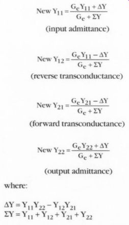
Accounting for the emitter or source resistor (conductor in this case because we are using admittance parameters), the new Y-parameters are given by:
New Y y= GeYy 1+ AY Ge +ZY (input admittance)
New Yj» = GeY11 -AY Ge +XZY (reverse transconductance)
GeYz1 -AY ade da Cc (forward transconductance)
GeYap +AY New Voz ==Peay | (output admittance) where:
--------
It is obvious that the forward transconductance, Y,;, can be reduced to zero by the correct value of emitter or source resistor, and the amplifier will have no gain. The load resistor doesn't even matter.
Raymond A. Futrell Great Falls, VA
+++++++++++++
HELP WANTED
I am trying to find out the input impedance for a Hafler DH 220 amplifier. I need to know so that I can properly set the crossover for a V andy subwoofer.
Any help is most appreciated.
Readers with information about this topic are encouraged to respond directly to the letter writer at the address provided-Eds.
READER-submitted TIPS
Audio Electronics offers readers the opportunity to share their knowledge and experience and show off their handiwork. If you're an audio enthusiast, then you probably have information to pass along to readers.
You may not think it's significant, but let us be the judge of that.
You may have solved a particular system design problem. Or a construction trick.
Or a clever circuit modification. Tell us your latest audio construction adventure.
Your experience could help others.
Chances are, if you've faced the problem then others have too. We're looking for what you've experienced.
Contribute to the wealth of information in this industry. Involved readers like you en sure that this industry will prosper. And we're willing to pay you a modest stipend for your efforts.
At the same time, you'll be putting a few bucks into your pocket, but, most of all, you'll become an active part of the audiophile community. Your work will be read by thousands of others. Remember, it's your magazine, and your contribution can make it even better.
Send your entries to: ___ expired!
Also see: