Sescom, Inc. 2100 Ward Drive, Henderson, NV 89051, (702) 565-3400, www.sescom.com.
Audio SIP-1 $20.
The Sescom Audio SIP-1 is a dual general-purpose noninverting gain amplifier. The single in-line PC board (SIP) measures only 1.06" x 0.875", with nine pins on standard 0.1" in-line spacings (Photo 1). This allows the SIP-1 to plug into a standard SIP socket.
Sescom advertises the SIPs as audio subsystems that you can place together to form a larger system. There are a total of 24 PC boards in the SIP family, along with two power-supply modules (more on this later).
The low-profile surface-mount components result in a board that is only 1/4" high. The single-layer tracks are on the component side of the board. The rear of the board has a stick-on label that defines all the pin connections.
Circuit Description
The schematic diagram for the Audio SIP 1 is shown in Fig. 1. The board uses the Rohm version of the NE5532 dual-audio op amp, the BA15532, in a SOP8 surface mount package. The 5532 has a maximum supply-voltage rating of +-22V DC rather than the +-18V DC limit of many op amps.
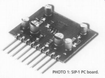
PHOTO 1: SIP-1 PC board.
The power-supply boards that support the SIP-1 (and the other SIPs in the family) are designed to furnish a conservative +18V DC to the SIP-1 at pin 4 (V-) and pin 6 (V+). The board has local 100nF ceramic decoupling capacitors for the op amp supply pins. The quality of the soldering and the symmetrical board layout are excellent.
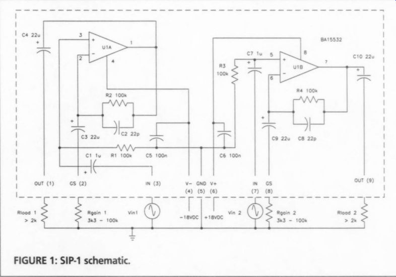
FIGURE 1: SIP-1 schematic.
Since each half of the dual op-amp circuit has the same layout, I will explain only one. The audio input signal at pin 3 (IN) is coupled through C1 to the noninverting input of U1A, with R1 establishing an input impedance of 100k. Feed back is provided by R2 and C2, which sets a feedback zero at 72kHz.
You then add an external resistor from pin 2 (GS) to ground pin 5 to increase the gain to as much as 30dB, at which the combination of the 3k3 gain resistor and C3 will set the LF 3dB response to 2.2Hz. The output is coupled by C4 to output pin 1 (OUT). All the coupling caps are aluminum electrolytics, and the 22pF feedback caps appear to be NPO ceramic chips.
While the 5532 itself can drive a 600 ohm load, this would raise the output LF 3dB response (C4 and the 600 ohm load) to 12Hz. In order to ensure a flat response down to 20Hz, the output load should be 2k or higher.
Measurements
There was a bit of confusion when I began building a test fixture for the SIP-1. The pin connections in the booklet did not agree with the decal on the back of the PC board. I traced the circuit with my ohmmeter before I made any of the connections.
I didn't make any rigorous audio measurements. The 5532 has been available for over 20 years and is a known entity, and the SIP-1 circuit is quite simple. I used a regulated lab-type dual power supply set to +-18V DC in place of the Sescom power-supply modules. I plugged the SIP-1 into a socket and wire wrapped my connections.
First I wired the SIP-1 as a pair of 6dB gain amplifiers (the lowest gain recommended by Sescom) by installing 100k resistors from pin 2 and pin 8 to pin 5 (ground). I used 5% carbon film resistors, since the values in the SIP-1 gain table are standard 5% values. Then I connected the two amplifiers on the SIP-1 in series, for a total of 12dB gain. I used load resistors of 47k, 2k, and 600 ohm.
I adjusted the sine oscillator for a 2V RMS output at 1kHz with a 47k load, and left it at that throughout the tests. I used the distortion test set 80kHz low pass filter during the distortion measurements to remove out of-band distortion products. The frequency response and distortion (THD+N) are shown in Table 1.
Results with the 600 ohm load are a bit better than expected because the 22uF output caps actually measured 25uF.
Square-wave response (2V pk-pk output with a 47k load) at 20Hz showed moderate tilt. The 1kHz square wave was just about perfect. The 20kHz square wave showed some rounding of the leading edges, with no overshoot or ringing.
Output clipping at 1% THD+N was 12.2V RMS from 20Hz-20kHz with the +18V DC power supplies.
Next I connected one of the SIP-1 amplifiers for its maximum gain of 30dB by installing a 3k3 resistor from pin 2 to pin 5 (ground). I did not connect them in series as before, since 60dB of gain would have required an unrealistically low input signal level, and added to the noise portion of THD+N. I again adjusted the
[...] the tests performed at 12dB. |
TABLE 1: FREQUENCY RESPONSE AND THD+N
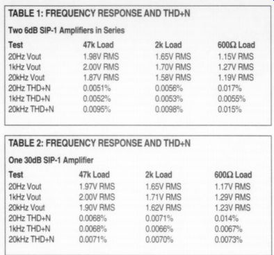
TABLE 2: FREQUENCY RESPONSE AND THD+N
Manufacturer's Specifications
Frequency response: +1dB 20-20kHz
Distortion: >0.01% 20-20kHz
Recommended gain range: 6dB-30dB (RGS 100k-3k3)

TABLE 3:AU Model SIP-1 SIP-2 SIP-3 SIP-4 SIP-5 SIP-6 SIP-7 SIP-8 SIP-9 SIP-10 SIP-11 SIP-12 SIP-13 SIP-14 SIP-15 SIP-16 SIP-17 SIP-18 SIP-19 SIP-20 SIP-21 SIP-22 SIP-23 SIP-24 SIP-PS SIP-18V
----
Other SIPs
As I said earlier, there are 24 SIP modules in the Sescom SIP family, and two power-supply modules. The complete family of products is given in Table 3. The Audio SIP Applications Guide has a number of schematics that show you how to implement a number of professional and consumer audio circuits.
For more information on the SIP family, consult the Sescom web page sescom.com/sips, where you can download schematics and PC board circuits.
------
DIO SIP FAMILY
Description Dual general-purpose gain amps Dual electronic mike input amps Dual electronic line input amps Dual electronic line output amps Line amp with buffer stage Dual summing amps Dual headphone amps Automatic level control-line level Dual voltage-controlled amplifier Four common buffer amps Dual electronic switch Video driver amplifier-three outputs Ducker (one audio signal has control over another) Electronic mike-line pad Auto feedback controller Function generator-sine/square wave Audio oscillator/meter driver Rumble scratch filter
Mike preamp/%sW amp
DC/DC converter
Dual gain amps-single supply Dual summing amps-single supply Limiter-fast attack/slow release Dual unity gain buffers AC power supply +-18V DC output, 25mA AC to +18V DC regulator circuit, 50mA
----------
Also see:
BOOK REVIEW--Elektor 300 Circuits