This article offers some worthwhile, user-installable upgrades to Monarchy Audio's Models 22C, 33, and 18B D/A converters (reviewed in AE 2/99), and their SE-100 Delux and SM-70 power amplifiers (reviewed in this issue, p.28).
Readers who visit the Burr-Brown site (burr-brown.com) may recall a suggestion for improving the performance of the PCM 1702 DAC chip. This technique involved connecting up to four DAC chips in parallel, and is described in the EVM-1702 evaluation-board data, still available for down load. Burr-Brown notes: "Superior performance and sound quality are produced by combining the parallel connection of four DACs per channel. This parallel-connection technique produces very low THD+N performance (up to -100dB) and wide dynamic range (up to 112dB)."
Parallel-Connection Technique
You can apply this technique to other DAC chips as well, including Burr-Brown PCMG63P-K, used in the Monarchy 22C and 33, and Analog Devices' AD1860N used in the Monarchy 18B. When Mr. C. C. Poon of Monarchy Audio first suggested this mod, I raised the question with Robert Adams of Analog Devices.
In an e-mail reply to my inquiry, Adams noted: "Adding a parallel DAC always improves the noise and dynamic range. This is because the noise between the two DACs is uncorrelated, but the signal is correlated. This gives rise to the “3dB-per doubling” rule, where every time you double the number of DACs, you get an extra 3dB of signal-to-noise ratio. You might also expect an improvement in distortion on average, since the accuracy of the major carry steps should average out , but this would reliably apply only to a large number of DACs in parallel.
Monarchy now recommends a parallel DAC mod as an upgrade for owners of the 22C, 33, and 18B. Monarchy calls this the "piggyback upgrade," since the installation involves simply soldering a second DAC chip on top of the existing one, as shown in Fig. 1. (Two chips in parallel is a practical limit if you are retrofitting an existing product.) Because you must modify both the left and right channels, you need to purchase two DAC chips of exactly the same type used in the D/A converter.
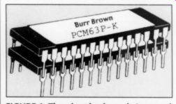
FIGURE 1: The piggyback mod. A second DAC chip is simply placed atop the
existing one. The pins are then carefully soldered together with a low-wattage
iron.
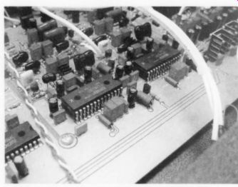
PHOTO 1: The piggyback DAC mod installed in a model 33 D/A converter. This
mod can be performed at the factory or by the user.
Although it's simple in concept, this mod is only for those who are extremely proficient with a soldering iron. Photo 1 shows a set of piggyback PCM 63P-K chips installed in a 22C, and Photo 2 a set of AD-1860N chips installed in an 18B. I recommend a soldering iron with a fine pencil-point tip and a heating element no higher than 30W. Be sure to take the a formed usual precautions regarding static electricity, since these chips are easily dam aged by accidental static discharge.
If you purchase the upgrade chips for the 22C or 33 from Monarchy, they even include a soldering iron. In my opinion, if you don't already own one, you have no business performing this mod. Monarchy will also perform the mod for you, but this nearly doubles the cost. You can also purchase the Burr-Brown chips from Digi-Key, but be sure that you specify the select "K" version.
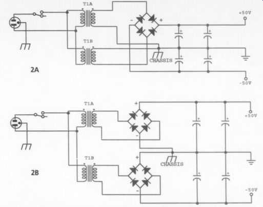
FIGURE 2: 2A is the original SE-100 rectifier circuit. 2B reflects the changes
required to accommodate the new rectifier bridges. A separate bridge is used
for the positive and negative rails.
Pin-Soldering Procedure
It will be easier to install the new chips if you straighten the pins first (as supplied, they are usually at an angle). With the pins straightened, you can fit the new chip atop the existing one, extending the pins of the new chip over the wide portions of those on the existing chip, where you will solder them.
To help hold the new chip in place, tack-solder the pins on opposite corners of the chip.
Once two corners have been se cured, solder the other pins.
Then go back and redo the corner pins to make sure you have clean sol der joints. Be careful not to use excessive heat, and avoid solder bridges! If you bridge two pins, you can remove the bridge with a desoldering tool, such as Radio Shack's #64-2060. Repeat the process for the other channel.
If you upgrade a Model 18B, you may wish to check the linearity of the paralleled AD1860N chips and readjust the trimpots on the PC board if necessary.
You will need a test CD with a 1kHz sine wave recorded at a level of < 60dB. 1 use he Hi-Fi News and Record Review, Test CD II, track 35 (HFN015).
Observe the converter's outputs on a cope, and adjust each trimpot to minimize the notch at the zero crossing. Chances are, if the adjustment was satisfactory before you added the piggyback hips, it will be correct afterward, but if you have the test gear, I recommend checking. If you use a track recorded at a level lower than -60dB, the display will contain so much noise that you will have difficulty seeing the sine wave. Like all current DAC chips, the PCM63PK chips require no trimming.
The piggyback upgrade is sonically worthwhile, increasing low-level detail and ambience retrieval. The 18-bit Model 18B is admittedly dated, but Monarchy has reduced its price to $299, including he piggyback mod. Since paralleled DACs produce twice the output current, he current-to-voltage converter in the D/A unit will now output twice as much voltage as before. I highly recommend changing the output-buffer gain to unity, as I described in the 2/99 review.
Low-Noise Rectifiers
Monarchy's SM-70 and SE-100 Delux power amplifiers are supplied with conventional bridge rectifiers, as are most power amps. Mr. Poon has recently discovered an upgrade for these rectifiers, the low-noise D6SBO0L, made in Japan by Shindengen. These replacement rectifiers are rated at 6A per bridge, so a pair of them is required for the SE-100 Delux, re placing the single bridge originally used.
Figure 2 shows the original and revised power-supply circuits for the SE-100.
The Monarchy power amps use a single toroidal power transformer with dual secondary windings. In the original con figuration, with a single bridge, the secondary windings were connected together to form a grounded center-tap (Fig. 2A). The low-noise rectifier mod re quires separating the two windings so that each feeds its own rectifier bridge (Fig. 2B).
Monarchy uses push-on crimp connectors to make the connections to the existing rectifier bridge. The double red and double blue wires are the positive and negative rectifier outputs, which go to a connector on the main PC board. The single blue and single red wires are the AC inputs to the rectifier. After unplugging the connectors from the old rectifier, cut off the crimp connectors, strip 12" of insulation from each wire and tin each one (twist the bare ends of the double red and double blue pairs together before tinning).
The SE-100 chassis ground point is right in front of the main PC board, easily accessible if you remove the rear panel of the amplifier and slide the board back a bit. Temporarily remove the grounding screw, and cutoff the grounding lug connected to the two transformer windings. Make a twisted pair of each pair of transformer leads from the two windings, blue/orange and yellow/red. Strip 1/2" of insulation from each transformer lead, and tin the bare ends. Since the colors of transformer leads may vary, I strongly suggest checking each pair of windings with an ohm meter to make certain that you have identified them correctly.
Heatsinking
The new, low-noise rectifiers run only moderately warm in the SE-100 Delux amp, and don't require a huge amount of heatsinking. Mr. Poon suggested bolting the rectifiers directly to the transformer washer. I don't like this idea for two reasons: first, toroidal transformer washers are rarely perfectly flat once they've been used, so the washer probably won't make a firm mechanical contact with the rectifier; second, I prefer that the heatsink be made of aluminum rather than permeable metal.
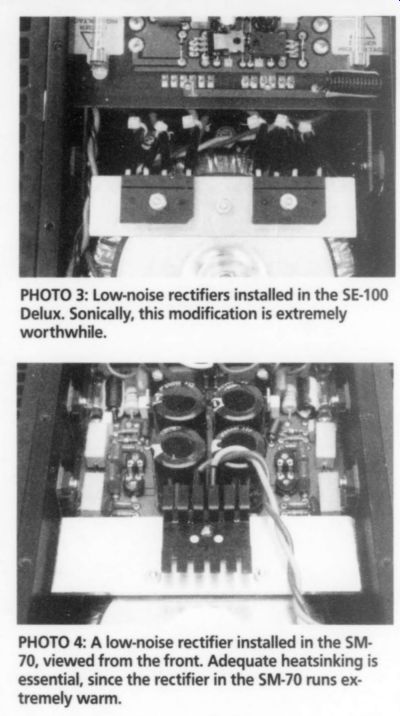
PHOTO 3: Low-noise rectifiers installed in the SE-100 Delux. Sonically, this
modification is extremely worthwhile.
My solution is shown in Photo 3. I made a heatsink out of 1" aluminum stock, 1/8" thick. You can buy this at your local hardware store. For each amplifier, cut a piece 5" long. Bolt the rectifiers to the heatsink, and the heatsink to the transformer washer. Use 4-40 x 12" flat-head machine screws, nuts, and washers.
Whenever you drill holes in metal, you should deburr them with a countersink or a large drill bit. After you've drilled the three holes in the heatsink and the single hole in the transformer washer, be sure you countersink the washer and the heatsink holes for the flat-head screws.
Insert the screws from the bottom of the heatsink/transformer washer assembly with the lock washers and nuts on top.
Use thermal compound between the rectifiers and the heatsink.
The exact position of the rectifiers on the heatsink isn't critical-mine are mounted so 1/2" of heatsink extends be yond each rectifier, as shown in Photo 3. After you've mounted the rectifier/ heatsink assembly to the transformer washer, reinstall the transformer washer with the original hardware.
Soldering the Wires
You will need to make a pair of 14AWG wires to connect the new rectifier bridges to the chassis ground point. I recommend soldering both wires to a common ground lug, making each wire long enough to reach the rectifier terminals (don't make any connections to the rectifiers yet). Strip and tin the other ends. Now, attach this assembly and the other ground wires to the chassis ground point, using the original grounding screw. If any of the other ground wires were crimped to their lugs, solder them at this time.
The rectifier bridges have long, flat leads. I suggest placing the tinned wire ends flat against the rectifier leads, and soldering them in place. I use Radio Shack's "Sturdy Extra Hands," a contraption with a pair of alligator clips and adjustable ball joints mounted on a heavy metal base. The alligator clips hold the wires in place while you solder. If you place the amplifier top plate sideways, across the rear of the amplifier, you can set "Extra Hands" on top of it.
Be sure to slip sleeving over all leads before you solder. Once you've soldered them, slip the sleeving over the bare connections and secure it with some small nylon cable ties. As you face the amplifier as shown in Photo 3, the eight wires attached to the rectifiers are, from left to right: double blue, transformer blue, transformer orange, ground, ground, transformer yellow, transformer red, double red.
I strongly suggest powering up your modified amplifiers slowly with a Variac, carefully monitoring the positive and negative supply rails on the PC board to make sure the voltages are headed in the right direction. In the orientation in Photo 3, the left fuse is the negative rail, and the right fuse is the positive.
The rails should be +/- 50V at full line voltage. This mod is equally applicable to the SE-100 Basic amplifier.
SM-70
In the SM-70, you can still use a single rectifier bridge. The existing bridge is soldered directly to the PC board. Cut each of its four leads, leaving enough lead length in the PC board to allow you to grab the leads with a pair of long-nose pliers. For future reference, note which holes on the PC board were connected to the positive and negative rectifier leads. Heat the solder joints, remove the old leads, and clean the holes with a de soldering tool. Also remove the transformer leads from the PC board, noting the color of the lead removed from each hole (mine were red and blue).
Even though the SM-70 amplifier has much lower-rated power than the SE-100 Delux, the rectifier bridge runs much hot ter. This is due to the heavy Class A biasing of the SM-70 output stage. Robust heatsinking is essential for long rectifier life. Photos 4 and 5 show my solution to the problem, using a 42" length of right angle aluminum stock, 1" x 1 3/8." x 14" thick.
Sources
Monarchy Audio Swift Ave., #21, S. San Francisco, CA 94080, 650-873-3055, FAX 650-588-0335
Self-upgrade for Models 22C and 33-$100. Includes two Burr-Brown PCM63P-K DAC chips, a 30W soldering iron, solder, and an instruction sheet.
Factory upgrade for Models 22C and 33-$180. Send your unit back to Monarchy for a three-day turn-around.
They will install the mod, check the unit for optimum performance, install the Blue-Dot upgrade if it's not already there (see review in 2/99 for details), perform a listening test, ship the unit back via UPS, and renew the warranty for 12 months.
Self upgrade for Model 18B-$20 plus $5 shipping. Includes two Analog Devices AD-1860N DAC chips.
Monarchy does not offer the option of returning your 18B for this mod.
Complete, new Model 18B D/A converter with piggy backmod-$299.
Shindengen D6SB6OL low-noise rectifiers for SE-100 and SM-70 power amps--$10 each.
Digi-Key C " 701 Brooks Ave. South Thief River Falls, MN 56701-0677 800-344-4539, FAX 218-681-3380
digikey.com
Burr-Brown PCM63P-K DAC chips
Aavid heatsink-#HS-114-ND Chemtronics heatsink grease-#CT40-5-ND
Hardware store 1" x 1.25" x 1/8"-thick aluminum angle stock, 5" long (for SM-70 rectifier) 1" x 1/8"-thick flat aluminum stock, 4 1/2" long (for SE 100 rectifiers) 4-40 x 1/2" flat-head machine screws, lockwashers, and nuts
- - - (pit washer.
The rectifier is mounted on the aluminum heatsink, which, in turn, is bolted to the transformer washer with a pair of 4-40 x 12" flathead machine screws.
The wider dimension of the heatsink is parallel to the transformer washer, and the shorter dimension faces downward, as shown in Photo 5. You should position the heatsink so there is ample clearance between it and the fuses on the PC board. The downward-facing surface should not make physical contact with the power transformer.
Countersink holes for the flat-head screws, as previously described. Place 4 40 nuts between the transformer washer and the heatsink to thermally isolate them. Also place an Aavid HS-114-ND heatsink on top of the rectifier to provide some additional heat dissipation. Be sure to use thermal compound between the rectifier and both heatsinks. You'll need to drill a mounting hole in the Aavid heatsink, since the factory holes are for TO-220 devices. Once you've assembled the heatsink/transformer washer assembly, reinstall the transformer washer with the original hardware.
Connecting the Rectifier
All you need do now is connect the bridge rectifier. Use the same procedure for connecting wires to the rectifier bridge pins as already described for the SE-100. Be sure to use sleeving on all four rectifier leads. Connect short leads between the positive and negative outputs of the rectifier and the corresponding holes on the PC board.
Removing the old rectifier left four vacant holes on the PC board-the DC in puts are the outer ones. The middle rectifier holes, and the holes left vacant by removal of the transformer leads, are not used. Solder the power-transformer leads directly to the center leads of the rectifier. Orient the transformer leads so the colors are the same, left and right, as they were before you removed them from the PC board.
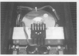
PHOTO 5: Rear view of the SM-70 rectifier mod. Two 4-40 nuts serve as a spacer
between the home-brew aluminum heatsink and the transformer mounting washer.
In Photo 5, the blue lead is on the left and the red on the right.
Slowly power up the amplifier with a Variac, carefully monitoring the positive and negative rail voltages to make sure they are headed in the right direction. The minus designation on the negative-rail filter capacitor is closest to the negative-rail fuse. The positive-rail fuse is on the opposite side. You should have +30V at full line voltage (early samples of these amplifiers had transformers that yielded +/- 26V rails).
I discussed the benefits of using low noise rectifiers in my article "Pooge 5.5: More DAC960 Modifications" (TAA 1/94).
That article also contains an excellent sidebar by Rick Miller on measured differences in rectifier diodes. In that article, Rick and I each mentioned improvements in soundstage depth and width, clarity and definition, smoothness and articulation. The low-noise rectifier modifications have yielded similar improvements in the already excellent Monarchy power amps.
--------
Also see:
Monarchy Audio SM-70 and SE-100 Delux Power Amplifiers