18. CD subcode
Subcode is essentially an auxiliary data stream which is merged with the audio samples, and which has numerous functions. One of these is to assist in locating the beginning of the different musical pieces on a disk, and providing a catalogue of their location on the disk and their durations. A further vital function is to convey the status of pre-emphasis in the recording, so that de-emphasis can be automatically selected in the player. The subcode information in CD is conveyed by including an extra byte, which corresponds to one EFM symbol, in the main frame structure.
As the format of the disk is standardized, the player is designed to route the subcode byte in the frame to a different destination from that of the audio sample bytes. The separation is based upon the physical position of the subcode byte in the frame. The player uses the sync pattern at the beginning of the frame to reset a byte count so that it always knows how far through the frame it is. As a result, subcode bytes will be separated from the data stream at frame frequency.
It has been shown that there are 98 bytes in a subcode block, since this results in a subcode block rate of exactly 75Hz. This frequency can be used to run the playing-time display.
It is necessary for the player to know when a new subcode block is beginning. This is the function of the subcode sync patterns which are placed in the subcode byte position of two successive frames. There are more than 256 legal fourteen-bit patterns in EFM, and two of these additional legal channel-bit patterns are used for subcode-block synchronizing. The EFM decoder will be able to distinguish them from the patterns used to represent subcode-data bytes. For this reason it is impossible to describe the subcode sync patterns by a byte, and they have to be specified as fourteen channel bits.
FIG. 51 shows the subcode sync patterns, and illustrates the contents of the subcode block. After the subcode sync patterns, there are 96 bytes in the block. The block is arranged as eight 96-bit words, labeled P Q R S T U V and W. The choice of labeling is unfortunate because the letters P and Q have already been used to describe the redundancy in the error-correction system. The subcode P and Q data have absolutely nothing to do with that. The eight words are quite independent, and each subcode byte in a disk frame contains one bit from each word. This is a form of interleaving which reduces the damage done to a particular word by an error.
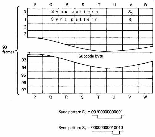
FIG. 51 Each CD frame contains one subcode byte. After 98 frames, the
structure above will repeat. Each subcode byte contains 1 bit from eight 96
bit words following the two synchronizing patterns. These patterns cannot be
expressed as a byte, because they are 14 bit EFM patterns additional to those
which describe the 256 combinations of eight data bits.
The P data word is used to denote the start of specific bands (having the same meaning as the bands on a vinyl disk) in the sound recorded.
The entire word is recorded as data ones during the start-flag period. It can be used even where there is no audible pause in the music, since the start point is defined as where the P data become zeros again. The CD standard calls for a minimum of two seconds of start flag to be recorded.
This seems wasteful, but it allows a very simple player to recognize the beginning of a piece easily by skipping tracks. The fact that every bit is a one means that it is not necessary to wait for subcode block sync to be found before finding pause status on the disk track. The two-second-flag period means that the status will be seen a few tracks in advance of the actual start-point, helping to prevent the pickup from overshooting. If a genuine pause exists in the music, the start flag may be extended to the length of the pause if it exceeds two seconds. Again, for the benefit of simple players, the start flag alternates on and off at 2Hz in the lead-out area at the end of the recording.
At the time of writing the only other defined subcode data word is the Q word. This word has numerous modes and uses which can be taken advantage of by CD players with greater processing and display capability.
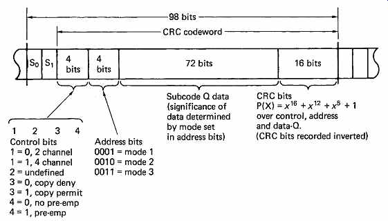
FIG. 52 The structure of the Q data block. The 72-bit data can be interpreted
in three ways determined by the address bits.
FIG. 52 shows the structure of the Q subcode word. In the 96 bits following the sync patterns, there are two four-bit words for control, a 72-bit data block, and a sixteen-bit CRC character which makes all 96 bits a codeword.
The first four-bit control word contains flags specifying the number of audio channels encoded, to permit automatic decoding of four channel disks, the copy-prohibit status and the pre-emphasis status. Since de emphasis is often controlled by a relay or electronic switch in the analog stages of the player, the pre-emphasis status is only allowed to change during a P code start flag.
The second four-bit word determines the meaning of the subsequent 72-bit block. There can be three meanings: mode 1, which tells the player the number and start times of the bands on the disk; mode 2, which carries the disk catalogue number; and mode 3, which carries the ISRC (International Standard Recording Code) of each band. Of all the subcode blocks on a disk, the mode 1 blocks are by far the most common.
Mode 1 has two major functions. During the lead-in track it contains a table of contents (TOC), listing each piece of music and the absolute playing time when it starts. During the music content of the disk, it contains running time.
FIG. 53 shows that the 72-bit block is subdivided into nine bytes, one of which is unused and permanently zero. Each byte represents two hexadecimal digits where not all codes are valid. The first byte in the block is the music number (MNR), which specifies the number of the track on the disk; where in this context 'track' corresponds to the bands on a vinyl disk. The tracks are numbered from one upwards, and the track number of 00 indicates that the pickup is in the lead-in area and that the rest of the block contains an entry in the table of contents.

FIG. 53 General format of Q subcode frame in mode 1. There are eight
unused bits, leaving eight active bytes. First byte is music or track number,
which determines meaning of remaining bytes.
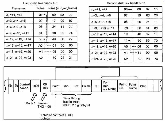
FIG. 54 During lead-in TNO is zero and Q subcode builds up a table of
contents using numbered points with starting times. For multidisk sets, the
band numbering can continue from one disk to the next, and there are point-limit
codes A0 and A1 which specify the range of bands on a given disk. The example
of a two-disk set is given, with five bands on the first disk and six bands
on the second. Point = 00-99, point = music number, and point (min, sec, frame)
denotes absolute starting time of that music number. This forms an entry in
TOC. Point = A0 hex, point min byte = music number of first band on this disk,
denotes beginning MNR of TOC. Point = A1 hex, point min byte = music number
of last band on this disk, denotes end MNR of TOC.
Point = A2 hex, point (min, sec, frame), denotes absolute starting time of lead-out track.
The table of contents is built up by listing points in time where each track starts. One point can be described in one subcode block. FIG. 54 shows that the second byte of the block is the point number. The absolute time at which that point will be reached after the start of the first track is contained in the last three bytes as point minutes, point seconds and point frames. These bytes are two BCD digits, where the maximum value of point frame is 74. As there is only error detection in the Q data, the point is repeated in three successive subcode blocks. The number of points allowed is 99, but the track numbering can continue through a set of disks. For example, in a two-disk set, there could be five tracks, 1 to 5, on the first disk, and six tracks, 6 to 11, on the second disk. Clearly the first point on the second disk is going to be point 6, and to prevent the player fruitlessly looking for points that are absent, the point range is specified.
If the point byte has the value A0 hex, the point-minute byte contains the number of the first track on the disk, which in the example given would be 6. If the point byte has the value A1 hex, the point-minute byte contains the number of the last track on the disk, which would here be 11.
A further point is specified, which is the absolute running time of the start of the lead-out track, which uses the point code of A2 hex. These three points come after the actual music start points. During the lead-in track, the running time is counted by the minute, second and frame bytes in the block.
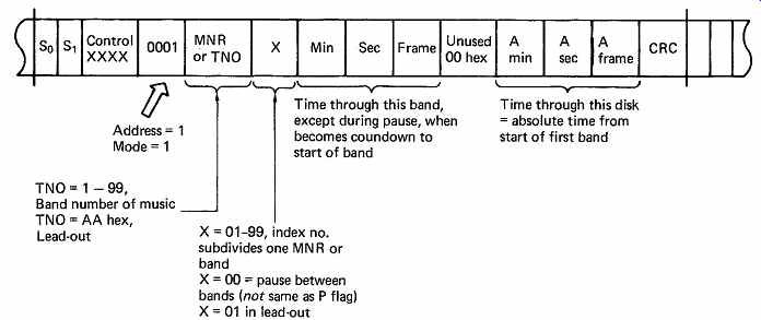
FIG. 55 During music bands TNO. is 01-99, and subcode shows time through
band and time through disk. The former counts down during pause. Each band
can be subdivided by index count X.
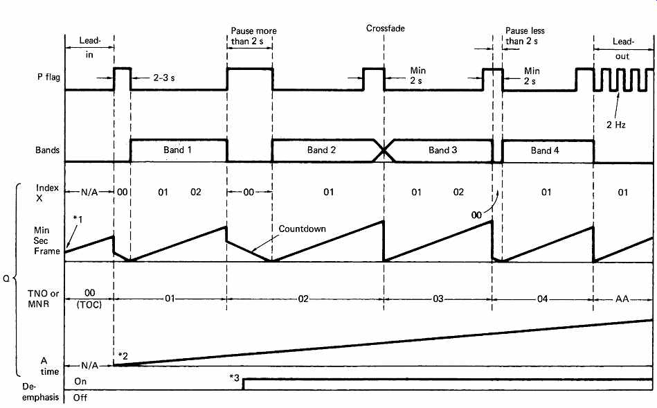
FIG. 56 The relationship of P and Q subcode timing to the music bands.
P flag is never less than 2 s between bands, whereas index reflects actual
pause, and vanishes at a crossfade. Time counts down during index 00.
*1: lead-in time does not have to start from zero;
*2: A time must start from zero;
*3: de-emphasis can only change during pause of 2 s or more.
If the first byte of the block is between 00 and 99, the block is in a music track, and the meaning shown in FIG. 55 applies. The running time is given in three ways. Minute, second and frame are the running time from the start of that track, and A(bsolute)min, Asec and Aframe are the running time from the start of the first track on the disk. The third running-time mode employs the index or X byte. When this is zero, it denotes a pause, which corresponds to the P subcode's being 1. During this pause, which precedes the start of a track, the running time counts down to zero, so that a player can display the time to go before a track starts to play. The absolute time is unaffected by this mode. Non-zero values of X denote a subdivision of the track into shorter sections. This would be useful to locate individual phrases on a language-course disk, or the individual effects on a sound-effects disk. FIG. 56 shows an example of the use of P and Q subcode and the relationship between them and the music bands.
Mode 2 of the Q subcode allows the recording of the barcode number of the disk, and is denoted by the address code of 2 in the block as shown in Figure 12.57. The 52-bit barcode, along with twelve zeros and a continuation of the absolute frame count, are protected by the CRC character. If this mode is used, it should show up at least once in every 100 subcode blocks and the contents of each block should be identical.
The use of the mode is not compulsory.

FIG. 57 In mode 2, the catalogue number can be recorded. This must always
be the same throughout the disk, and must appear in at least one out of a hundred
successive blocks.
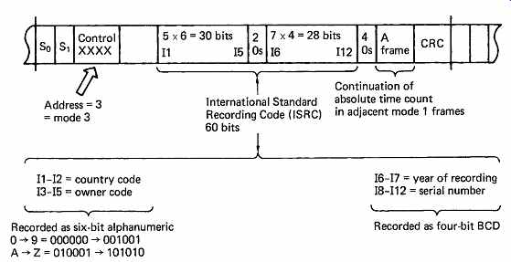
FIG. 58 ISRC format in mode 3 allows each band to have a different code.
All mode 3 frames must be the same within same TNO. Must appear in at least
one out of every hundred successive blocks. Not present in lead-in or lead-out
tracks.
Mode 3 of Q subcode is similar to mode 2, except that a code number can be allocated to each track on the disk. FIG. 58 shows that the ISR code requires five alphanumeric characters of six bits each and seven BCD characters of four bits each. Again the mode is optional but, if used, the mode 3 subcode block must occur at least once in every 100 blocks.
The R to W subcode is currently not standardized, but proposed uses for this data include a text display which would enable the words of a song to appear on a monitor in synchronism with the sound played from the disk. A difficulty in this area is the requirement to support not only the kind of alphanumerics in which this guide is written but also the complex Kanji characters which would be needed for the Japanese market.
19. MD table of contents
The TOC of the pre-recorded MiniDisc is basically similar to the CD TOC as it performs the same function. Recordable MiniDiscs have a different approach. Recordable MD is more like a hard disk than a real-time audio recorder, and the buffer memory allows continuous audio listening from records which are fragmented across the disk surface. Thus the UTOC (user table of contents) of the recordable MD is more like the directory of a data disk (see Section 10). UTOC contains one entry for each numbered recorded item which lists the physical cluster addresses at which the data for that item are recorded. When the user selects the number of an item, the player reads the UTOC in order to locate the data addresses. Item numbers are contiguous, so if an item is deleted or if two items are merged, the numbering scheme beyond will move up by one. It is not necessary to actually erase unwanted recordings. Instead the directory entry is deleted and then as far as the system is concerned the recording no longer exists and the clusters it uses are available for overwriting.
FIG. 59 shows some examples of UTOC operations. Despite the internal complexity, the disk mapping is taken care of by a micro processor and the user simply selects item numbers.
20. CD player structure
The physics of the manufacturing process and the readout mechanism have been described, along with the format on the disk. Here, the details of actual CD and MD players will be explained. One of the design constraints of the CD and MD formats was that the construction of players should be straightforward, since they were to be mass produced.
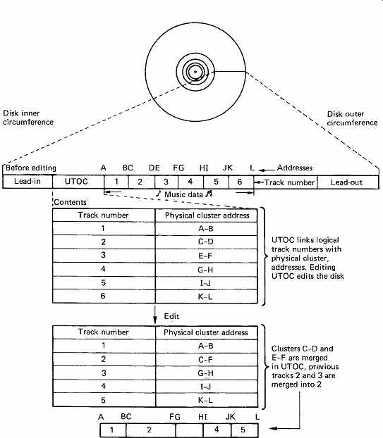
FIG. 59 Recordings on MD are accessed via the UTOC which functions like
a hard disk index. Editing is achieved simply by altering UTOC.
FIG. 60 shows the block diagram of a typical CD player, and illustrates the essential components. The most natural division within the block diagram is into the control/servo system and the data path. The control system provides the interface between the user and the servo mechanisms, and performs the logical interlocking required for safety and the correct sequence of operation.
The servo systems include any power-operated loading drawer and chucking mechanism, the spindle-drive servo, and the focus and tracking servos already described.
Power loading is usually implemented on players where the disk is placed in a drawer. Once the drawer has been pulled into the machine, the disk is lowered onto the drive spindle, and clamped at the center, a process known as chucking. In the simpler top-loading machines, the disk is placed on the spindle by hand, and the clamp is attached to the lid so that it operates as the lid is closed.
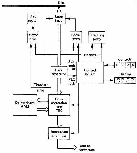
FIG. 60 Block diagram of CD player showing the data path (broad arrow)
and control/servo systems.
The lid or drawer mechanisms have a safety switch which prevents the laser operating if the machine is open. This is to ensure that there can be no conceivable hazard to the user. In actuality there is very little hazard in a CD pickup. This is because the beam is focused a few millimeters away from the objective lens, and beyond the focal point the beam diverges and the intensity falls rapidly. It is almost impossible to position the eye at the focal point when the pickup is mounted in the player, but it would be foolhardy to attempt to disprove this.
The data path consists of the data separator, timebase correction and the de-interleaving and error-correction process followed by the error concealment mechanism. This results in a sample stream which is fed to the convertors.
The data separator which converts the readout waveform into data was detailed in the description of the CD channel code. LSI chips have been developed to perform the data-separation function: for example, the Philips SAA 7010 or the Sony CX 7933. The separated output from both of these consists of subcode bytes, audio samples, redundancy and a clock. The data stream and the clock will contain speed variations due to disk run-out and chucking tolerances, and these have to be removed by a timebase corrector.
The timebase corrector is a memory addressed by counters which are arranged to overflow, giving the memory a ring structure as described in Section 1. Writing into the memory is done by using clocks from the data separator whose frequency rises and falls with run-out, whereas reading is done using a crystal-controlled clock, which removes speed variations from the samples, and makes wow and flutter unmeasurable. The timebase-corrector will only function properly if the two addresses are kept apart. This implies that the long-term data rate from the disk must equal the crystal-clock rate. The disk speed must be controlled to ensure that this is always true, and there are two contrasting ways in which it can be done.
The data-separator clock counts samples from the disk. By phase comparing this clock with the crystal reference, the phase error can be used to drive the spindle motor. This system was used in the Sony CDP 101, where the principle was implemented with a CX-193 chip, originally designed for DC turntable motors. The data-separator signal replaces the feedback signal which would originally have come from a toothed wheel on the turntable.
The alternative approach is to analyze the address relationship of the timebase corrector. If the disk is turning too fast, the write address will move towards the read address; if the disk is turning too slowly, the write address moves away from the read address. Subtraction of the two addresses produces an error signal which can be fed to the motor. The TBC RAM controller produces the motor-control signal. In these systems, and in all CD players, the speed of the motor is unimportant. The important factor is that the sample rate is correct, and the system will drive the spindle at whatever speed is necessary to achieve the correct rate. As the disk cutter produces constant bit density along the track by reducing the rate of rotation as the track radius increases, the player will automatically duplicate that speed reduction. The actual linear velocity of the track will be the same as the velocity of the cutter, and although this will be constant for a given disk, it can vary between 1.2 and 1.4m/s on different disks.
These speed-control systems can only operate when the data separator has phase-locked, and this cannot happen until the disk speed is almost correct. A separate mechanism is necessary to bring the disk up to roughly the right speed. One way of doing this is to make use of the run length limits of the channel code. Since transitions closer than 3T and further apart than 11T are not present, it is possible to estimate the disk speed by analyzing the run lengths. The period between transitions should be from 694 ns to 2.55s. During disk run-up the periods between transitions can be measured, and if the longest period found exceeds 2.55 s, the disk must be turning too slowly, whereas if the shortest period is less than 694 ns, the disk must be turning too fast. Once the data separator locks up, the coarse speed control becomes redundant. The method relies upon the regular occurrence of maximum and minimum run lengths in the channel. Synchronizing patterns have the maximum run length, and occur regularly. The description of the disk format showed that the C1 and C2 redundancy was inverted. This injects some ones into the channel even when the audio is muted. This is the situation during the lead-in track - the very place that lock must be achieved. The presence of the table of contents in subcode during the lead-in also helps to produce a range of run lengths.
Owing to the use of constant linear velocity, the disk speed will be wrong if the pickup is suddenly made to jump to a different radius using manual search controls. This may force the data separator out of lock, and the player will mute briefly until the correct track speed has been restored, allowing the PLO to lock again. This can be demonstrated with most players, since it follows from the format.
Following data separation and timebase correction, the error-correction and de-interleave processes take place. Because of the cross-interleave system, there are two opportunities for correction, first, using the C1 redundancy prior to deinterleaving, and second, using the C2 redundancy after de-interleaving. In Section 6 it was shown that interleaving is designed to spread the effects of burst errors among many different codewords, so that the errors in each are reduced. However, the process can be impaired if a small random error, due perhaps to an imperfection in manufacture, occurs close to a burst error caused by surface contamination. The function of the C1 redundancy is to correct single symbol errors, so that the power of interleaving to handle bursts is undiminished, and to generate error flags for the C2 system when a gross error is encountered.
The EFM coding is a group code which means that a small defect which changes one channel pattern into another will have corrupted up to eight data bits. In the worst case, if the small defect is on the boundary between two channel patterns, two successive bytes could be corrupted. However, the final odd/even interleave on encoding ensures that the two bytes damaged will be in different C1 codewords; thus a random error can never corrupt two bytes in one C1 codeword, and random errors are therefore always correctable by C1. From this it follows that the maximum size of a defect considered random is 17T or 3.9s. This corresponds to about a 5 m length of the track. Errors of greater size are, by definition, burst errors.
The de-interleave process is achieved by writing sequentially into a memory and reading out using a sequencer. The RAM can perform the function of the timebase-corrector as well. The size of memory necessary follows from the format; the amount of interleave used is a compromise between the resistance to burst errors and the cost of the de-interleave memory. The maximum delay is 108 blocks of 28 bytes, and the minimum delay is negligible. It follows that a memory capacity of 54 x 28 = 1512 bytes is necessary. Allowing a little extra for timebase error, odd/even interleave and error flags transmitted from C1 to C2, the convenient capacity of 2048 bytes is reached.
The C2 decoder is designed to locate and correct a single-symbol error, or to correct two symbols whose locations are known. The former case occurs very infrequently, as it implies that the C1 decoder has miscorrected. However, the C1 decoder works before de-interleave, and there is no control over the burst-error size that it sees. There is a small but finite probability that random data in a large burst could produce the same syndrome as a single error in good data. This would cause C1 to miscorrect, and no error flag would accompany the miscorrected symbols. Following de-interleave, the C2 decode could detect and correct the miscorrected symbols as they would now be single-symbol errors in many codewords. The overall miscorrection probability of the system is thus quite minute. Where C1 detects burst errors, error flags will be attached to all symbols in the failing C1 codeword. After de-interleave in the memory, these flags will be used by the C2 decoder to correct up to two corrupt symbols in one C2 codeword. Should more than two flags appear in one C2 codeword, the errors are uncorrectable, and C2 flags the entire codeword bad, and the interpolator will have to be used. The final odd/even sample de-interleave makes interpolation possible because it displaces the odd corrupt samples relative to the even corrupt samples.
If the rate of bad C2 codewords is excessive, the correction system is being overwhelmed, and the output must be muted to prevent unpleasant noise. Unfortunately digital audio cannot be muted by simply switching the sample stream to zero, since this would produce a click. It is necessary to fade down to the mute condition gradually by multiplying sample values by descending coefficients, usually in the form of a half cycle of a cosine wave. This gradual fade-out requires some advance warning, in order to be able to fade out before the errors arrive. This is achieved by feeding the fader through a delay. The mute status bypasses the delay, and allows the fade-out to begin sufficiently in advance of the error. The final output samples of this system will be either correct, interpolated or muted, and these can then be sent to the convertors in the player.
The power of the CD error correction is such that damage to the disk generally results in mistracking before the correction limit is reached.
There is thus no point in making it more powerful. CD players vary tremendously in their ability to track imperfect disks and expensive models are not automatically better. It is generally a good idea when selecting a new player to take along some marginal disks to assess tracking performance.
The control system of a CD player is inevitably microprocessor-based, and as such does not differ greatly in hardware terms from any other microprocessor-controlled device. Operator controls will simply interface to processor input ports and the various servo systems will be enabled or overridden by output ports. Software, or more correctly firmware, connects the two. The necessary controls are Play and Eject, with the addition in most players of at least Pause and some buttons which allow rapid skipping through the program material.
Although machines vary in detail, the flowchart of FIG. 61 shows the logic flow of a simple player, from start being pressed to sound emerging. At the beginning, the emphasis is on bringing the various servos into operation. Towards the end, the disk subcode is read in order to locate the beginning of the first section of the program material.
When track-following, the tracking-error feedback loop is closed, but for track-crossing, in order to locate a piece of music, the loop is opened, and a microprocessor signal forces the laser head to move. The tracking error becomes an approximate sinusoid as tracks are crossed. The cycles of tracking error can be counted as feedback to determine when the correct number of tracks have been crossed. The 'mirror' signal obtained when the read-out spot is half a track away from target is used to brake pickup motion and re-enable the track-following feedback.
The control system of a professional player for broadcast use will be more complex because of the requirement for accurate cueing. Professional machines will make extensive use of subcode for rapid access, and in addition are fitted with a hand-operated rotor which simulates turning a vinyl disk by hand. In this mode the disk constantly repeats the same track by performing a single track-jump once every revolution. Turning the rotor moves the jump point to allow a cue point to be located. The machine will commence normal play from the cue point when the start button is depressed or from a switch on the audio fader. An interlock is usually fitted to prevent the rather staccato cueing sound from being broadcast.
CD changers running from 12 volts are available for remote installation in cars. These can be fitted out of sight in the luggage trunk and controlled from the dashboard. The RAM buffering principle can be employed to overcome skipping as in MD, but a larger memory is required.

FIG. 61 Simple flowchart for control system, focuses, starts disk, and
reads subcode to locate first item of program material.
Personal portable CD players are available, but these have not displaced the personal analog cassette in the youth market. This is possibly due to the cost of player and disks relative to the Compact Cassette. The Compact Cassette is also more immune to rough handling. Personal CD players are more of a niche market, being popular with professionals who are more likely to have a quality audio system and CD collection. The same CDs can then be enjoyed whilst travelling.
21. MD recorder/player structure
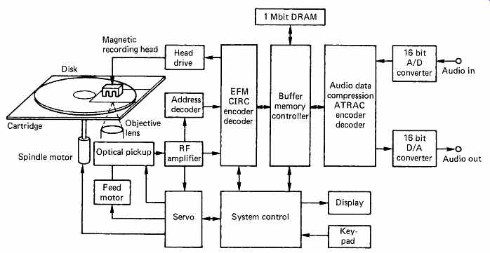
FIG. 62 MiniDisc block diagram. See text for details.
FIG. 62 shows the block diagram of an MD player. There is a great deal of similarity with a conventional CD player in the general arrangement. Focus, tracking and spindle servos are basically the same, as is the EFM and Reed-Solomon replay circuitry. The main difference is the presence of recording circuitry connected to the magnetic head, the large buffer memory and the data reduction codec. The figure also shows the VLSI chips developed by Sony for MD. Whilst MD machines are capable of accepting 44.1 kHz PCM or analog audio in real time, there is no reason why a twin-spindle machine should not be made which can dub at four to five times normal speed.
22. Structure of a DVD player
FIG. 63 shows the block diagram of a typical DVD player, and illustrates the essential components. The most natural division within the block diagram is into the control/servo system and the data path. The control system provides the interface between the user and the servo mechanisms, and performs the logical interlocking required for safety and the correct sequence of operation.
The servo systems include any power-operated loading drawer and chucking mechanism, the spindle-drive servo, and the focus and tracking servos already described for CD.
The data path consists of the data separator, the de-interleaving and error-correction process followed by a RAM buffer which supplies the MPEG decoders.
The data separator converts the EFM+ read-out waveform into data.
Following data separation the error-correction and de-interleave processes take place. Because of the interleave system, there are two opportunities for correction, first, using the inner code prior to de interleaving, and second, using the outer code after de-interleaving. As MPEG data are very sensitive to error the correction performance has to be extremely good.
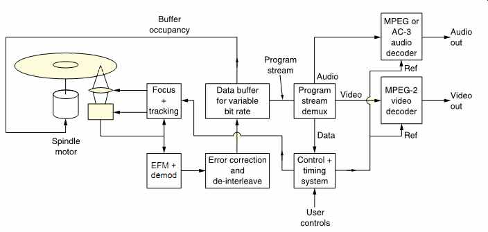
FIG. 63 A DVD player's essential parts. See text for details.
Following the de-interleave and outer error-correction process an MPEG program stream emerges. Some of the program stream data will be video, some will be audio and this will be routed to the appropriate decoder. It is a fundamental concept of DVD that the bit rate of this program stream is not fixed, but can vary with the difficulty of the program material in order to maintain consistent image quality. Although the bit rate allocated to the audio remains constant, the video bit rate doesn't. The bit rate is changed by changing the linear speed of the disk track. However, there is a complication because the disk uses constant linear velocity rather than constant angular velocity. It is not possible to obtain a particular bit rate with a fixed spindle speed.
The solution is to use a RAM buffer between the transport and the MPEG decoders. The amount of data read from the disk over the long term must equal the amount of data used by the MPEG decoders. The speed of the motor is unimportant. The important factor is that the data rate needed by the decoder is correct, and the system will drive the spindle at whatever speed is necessary so that the buffer neither underflows nor overflows.
The MPEG decoder will convert the compressed elementary streams into PCM video and audio and place the pictures and audio blocks into RAM. These will be read out of RAM whenever the time stamps recorded with each picture or audio block match the state of a time stamp counter.
If bidirectional coding is used, the RAM readout sequence will convert the recorded picture sequence back to the real-time sequence. The time stamp counter is derived from a crystal oscillator in the player which is divided down to provide the 90 kHz time stamp clock.
As a result the frame rate at which the disk was mastered will be replicated as the pictures are read from RAM. Once a picture buffer is read out, this will trigger the decoder to decode another picture. It will read data from the buffer until this has been completed and thus indirectly influence the disk speed.
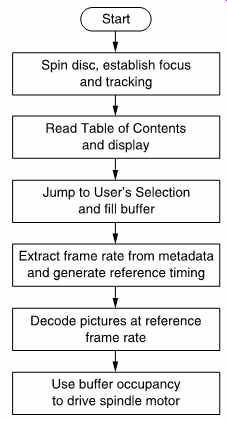
FIG. 64 Simple processes required for a DVD player to operate.
Owing to the use of constant linear velocity, the disk speed will be wrong if the pickup is suddenly made to jump to a different radius using manual search controls. This may force the data separator out of lock, or cause a buffer overflow and the decoder may freeze briefly until this has been remedied.
Although machines vary in detail, the flowchart of FIG. 64 shows the logic flow of a simple player, from start being pressed to pictures and sound emerging. At the beginning, the emphasis is on bringing the various servos into operation. Towards the end, the disk subcode is read in order to locate the beginning of the first section of the program material.
References:
1. Bouwhuis, G. et al., Principles of Optical Disc Systems, Bristol: Adam Hilger (1985)
2. Zernike, F., Beugungstheorie des schneidenverfahrens und seiner verbesserten form, der phasenkontrastmethode. Physica, 1, 689 (1934)
3. Mee, C.D. and Daniel, E.D. (eds) Magnetic Recording, Vol. III, New York: McGraw-Hill.
. ===