
by DANIEL DUFRESNE
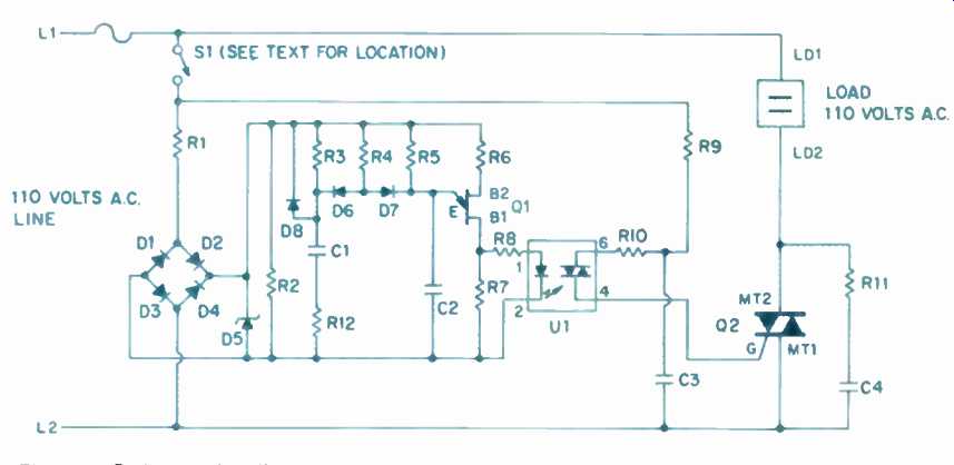
For those of you who have problems with turn-on surges, the circuit in Fig. 1, an a.c. slow-start circuit, can be of some help. When turned on, it slowly raises the voltage at the load terminals, limiting the inrush current. I 'have made one such unit, and it has been working perfectly for the last two years. (And it works fine here too.-E.P.) This is a phase-control circuit in which the turn-on phase delay of a triac is automatically varied, from a maximum to a minimum, at a preset rate. Changing the phase of the triac's turn-on point changes the output voltage. As a result, the power-supply capacitors in equipment connected to the circuit's output will charge slowly, limiting the turn-on current peaks through the component's parts (i.e., transformers, rectifiers, capacitors, switches, and associated wiring) to safer, lower values. This triac circuit has many advantages over circuits using relays or thermistors: It is all solid-state; it has a smooth turn-on of more than 200 steps; when properly designed, it generates less interference than other circuits, and finally, it is universal--that is, it does not need to be readjusted for each application. The circuit's power switch can be inserted in series with both the load and the control circuit or only in the control circuit. If the switch is for the control circuit alone, it can be a low-current type, chosen for esthetics.
The circuit is designed to power inductive loads, such as transformers, because these are the most common type of power-supply impedance and the most difficult triac-triggering situation. The difficulty resides in the fact that the turn-on signal must be applied long enough for the triac's current flow to be greater than the holding current.
In the case of an inductive circuit, this process takes time.

above: Fig. 1: Schematic diagram.
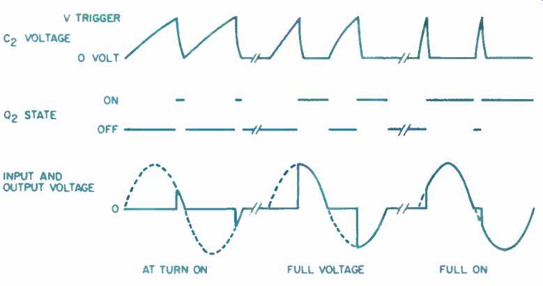
The circuit works as shown by the schematic (Fig. 1) and the timing diagram (Fig. 2). When power is turned on, capacitor C1 is at 0 V, diode D6 is conducting, and diode D7 is not. Capacitor C2 charges, through resistor R5, in a little less time than the duration of one half-cycle of the power-line frequency (i.e., less than 1/120 S). When Q1 triggers, it turns on the light-emitting diode in U1, which triggers the triac in U1. This turns on the main triac, Q2, delivering power to the load.
As C1 charges, current flowing through R4 and D7 charges C2 faster.
Therefore, the triac turns on earlier in the cycle, delivering more voltage. Finally, C1 is removed from the circuit by R3 and D6. As long as the full-on trigger point is less than 90°, there is no loss of power to the controlled devices.
This is because capacitor-input power supplies are peak detectors and thus respond to the peak of the voltage.
Further reduction of the full-on, turn-on phase angle lessens interference. The voltage delivered to the load is shown (in Fig. 2) to be zero after the output voltage's zero crossing. However, if the load is inductive, the triac will conduct until the current drops below the holding level.
The power supply shown here is unfiltered. A transformer can be used in place of R1, the dropping resistor. The circuit's time constant is about 2 S; to slow down the process, the time constant of R3 and C1 must be increased.
The MOC3011 triac opto-coupler (U1) triggers when the current through its built-in LED reaches 10 mA; the maximum permissible current through this diode is 50 mA. Resistor R8 limits the current to the LED; if a less sensitive coupler is used (such as the optional MOC3010, which triggers at 15 mA), the value of R8 should be decreased to 330 ohms.
Resistor R9 limits the trigger current delivered to Q2; again, its value should be adjusted to the device you use.
Note that the maximum permissible current through U1's triac is 100 mA and that the triggering current to Q2 should be less than this value. Network R10 and C3 form a protective snubber for the triac in U1, and R11 and C4 do the same for Q2. Triac Q2 must be mounted on a heat-sink with a thermal impedance of less than 5° C per watt.
Although this circuit limits the turn-on current surges to a reasonable level, some amplifiers will generate extraneous noise at their outputs during turn on. You won't know if yours is among them until you try it out.
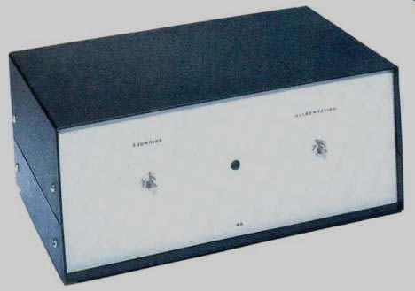
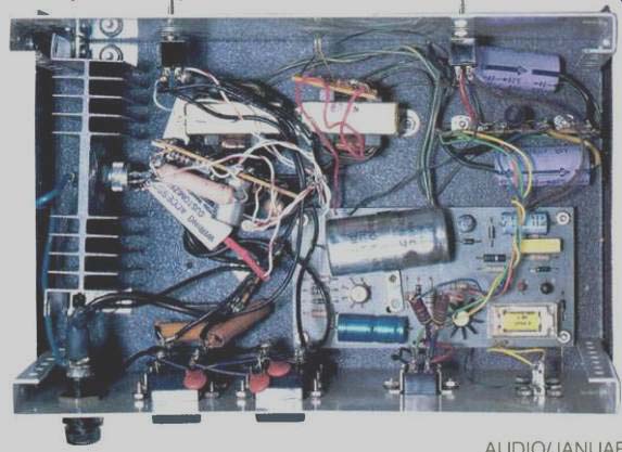
Physically, the circuit is quite small (except for Q2 and its heat-sink), and you may even be able to install it in the equipment that it powers. Care must be taken in wiring this circuit because of the hazardous voltages. Make sure to properly insulate all live parts. More information on triacs and slow-start circuits can be found in the SCR Manual, Including Triacs and Other Thyristors, Fifth Edition by D. R. Grafman (General Electric, 1972).

Fig.
2--Timing diagram. Transistor Q1 (not indicated) turns on when C2's voltage
(upper trace) is higher than Q1's trigger voltage; this discharges C2. Transistor
Q1 also triggers triac Q2 (middle traces), which delivers voltage to the
output (lower trace). The output-voltage buildup is best seen by comparing
the "on" times of Q2 with the output (solid lower
trace) just below it; the dashed lines show input from the a.c. line.
PARTS LIST:
Resistors:
(All 5%, 1/2 watt, unless otherwise noted)
R1-3.3 kilohms, 10%, 7 watts.
R2-10 kilohms.
R3-47 kilohms.
R4-4.7 kilohms.
R5-470 kilohms.
R6-1 kilohm, 1/2 watt.
R7-220 ohms.
R8-470 ohms.
R9-5.1 kilohms, 5 watts.
R10-180 ohms, 1/2 watt.
R11-100 ohms, 10%, 1 watt.
R12-5.1 kilohms.
Capacitors:
C1--470 µF, 25 V.
C2--0.1 µF, 25 V.
C3,-C4--0.033 µF, 600 V.
Miscellaneous:
D1 through D4, D6 through D8 -- 1N4004, 1-A, 400-PIV diodes.
D5--1N4744, 15-y, 10%, 1-watt zener diode.
Q1--2N4871 unijunction transistor.
Q2--2N5574, 15-A, 400-V triac.
U1--MOC3011, triac opto-coupler (the MOC3010 can also be used if R8 is changed; see text).
S1-Switch, single-pole, single throw 250 V a.c., sufficient current rating (see text).
Heat-sink, heat-sink grease, cabinet, solder, circuit board, etc.
Most electronic-parts stores, such as Radio Shack, will carry the above. If Q2 is not available locally, it can be purchased from Solid State Sales, P.O. Box 74, Somerville, Mass. 02143, (617) 547-7053, or at 139 Hampshire St., Cambridge, Mass. 02139. U1 can be obtained from Active Electronic Sales, P.O. Box 9100, Westboro, Mass. 01581, or from any supplier of Motorola semiconductor devices.
(Source: Audio magazine, Jan. 1986)
= = = =