MANUFACTURER'S SPECIFICATIONS
FM Tuner Section
Usable Sensitivity: 1.7 µV (10.0 dBf).
Capture Ratio: 1.5 dB.
Selectivity: 70 dB. S/N Ratio: 72 dB (Mono).
Image Rejection: 90 dB.
I.f. Rejection: 100 dB.
Spurious Rejection: 90 dB.
AM Suppression: 55 dB. THD: Mono at 1 kHz, 0.2 percent; Stereo at 1 kHz, 0.5 percent.
Frequency Response: 20 Hz to 16 kHz, +0.2 dB,-3 dB.
Stereo Separation @ 1 kHz: 45 dB.
AM Tuner Section
Sensitivity: 20 µV (external antenna).
Selectivity: 30 dB. S/N: 50 dB.
Image Rejection: 45 dB.
I.f. Rejection: 45 dB.
Amplifier Section
Power Output: 75 watts per channel continuous, 8-ohm loads, 20 Hz to 20 kHz (95 watts with 4-ohm loads). Rated THD: 0.1 percent.
Rated IM: 0.1 percent.
Damping Factor: Greater than 35.
Residual Noise:1 mV.
Input Sensitivity: Phono 1 & 2, 2.5 mV; AUX & Tape, 120 mV; Mike, 3 mV.
Phono Overload: 130 mV.
Hum and Noise (A Weighted): Phono, 70 dB; Mike, 70 dB; High Level, 90 dB.
Frequency Response: Phono, RIAA ±1 dB, High Level, 10 Hz to 35 kHz, ±0.5 dB.
Tone Control Range: Bass, ±10 dB @ 100 Hz; Midrange, ±5 dB @ 1 kHz, Treble, ±10 dB @ 10 kHz.
Filter Cut-Off Frequency: High, 8 or 12 kHz (12 dB/octave), Low, 15 or 30 Hz (12 dB/octave).
General Specifications
Power Consumption: 350 watts.
Dimensions: 20 7/8 in. (53 cm) W x 6 11/16 in. (17 cm) H x 13 11/16 in. (35 cm) D.
Price: $549.95.
-----------------------
In earlier days, I used to regard stereo receivers as being in two distinct classes: Those manufactured by major, well-known companies and those manufactured by lesser known makers under contract to retail chain stores. These days, it is almost impossible to distinguish between these two receiver categories, as some of the retail chains of audio dealerships have grown to the point where they can hire the engineering and production facilities of highly qualified high-fidelity component manufacturers. In fact, it is rumored that many of the "name brand" manufacturers also produce "private label" sets for such retail outlets. The Project/One brand is one that was developed for the Playback, Inc., retail outlets based in and around the Chicago area.
The front panel of the Project/One Mark IVB stereo AM/FM receiver suggests that Playback, Inc., was not quite ready to tread new design grounds but rather "borrowed" the best features and layout from several of the better known receivers around. The face plate is all gold-anodized in color, while the dial area features the gently rear-sloping configuration for easier visibility and a light-colored background upon which are inscribed the frequency calibrations for AM and FM. Calibration markings for the FM are at 0.5 MHz intervals, with AM markings less well defined. Above the dial scales are four separate meters, two for signal-strength and center-of channel tuning, the other two calibrated in watts for left- and right-channel power-output indications. To the right of the meters are a series of six illuminated strip-lights which indicate stereo FM reception, power-on, and program source selection. The flywheel-coupled tuning knob is just to the right of the dial opening, as are an FM muting switch (for silent interstation tuning) and a microphone input jack. Controls and switches along the lower section of the panel include a power On/Off button, speaker selector (with provisions for choosing any two out of three sets of connected speakers), two position low- and high-cut filter levers, bass, midrange, and treble tone controls, balance, master volume (step-detented) and program selector switch, and five additional lever switches. These last handle loudness, audio muting, mono/stereo switching, tape monitoring (of up to two connected decks), and tape dubbing. Tape-1 input and output circuits are duplicated in the form of stereo phone jacks on the front panel (in parallel with those at the rear), while a stereo headphone jack is located at the extreme lower left of the panel, just below the power switch.
The rear panel is equipped with three sets of spring-loaded speaker terminals (color coded and requiring only simple insertion of stripped ends of wire), a line fuseholder, and switched and unswitched a.c. receptacles at the right. At the upper left are the usual 300and 75-ohm antenna terminals, AM antenna terminals, a pivotable ferrite-bar AM antenna, and a chassis ground terminal. Two sets of phono-input jacks, the aforementioned tape-out and tape-in jack sets (including a DIN connector for the Tape-2 circuits) and preamp out/ main amp-in jacks which are supplied with interconnecting wire jumpers.
Internal Construction
No schematic diagram was supplied with the Project/One Mark IVB receiver, but we did examine its layout and construction, after quick and easy removal of the chassis from its four-sided wood cabinet. In addition to the self-contained front end, which utilizes a four-section tuning capacitor for FM and a two-gang arrangement for AM, there are nine other circuit board modules. Front-panel switches and controls are all directly mounted to a long voltage-amplifier, tone-control circuit board which makes for a minimum amount of inter module direct wiring. What little interconnection wiring exists is carefully harnessed and neatly dressed in as clean a layout as we have seen for any receiver. Identical power output modules are vertically mounted with output transistors mounted separately nearby on a single heavy heat sink structure. The power transformer seemed a bit on the small side for a receiver in this power category but was later proven to be adequate for its task. Short circuit protection is afforded by a relay-type protection circuit which also delays turn-on of the unit for a few seconds after the power switch is depressed to prevent pops and thumps from reaching speakers. Six internal fuses (in addition to the externally accessible line fuse) are associated with the d.c. voltage supplies but are not regarded as customer replaceable. All circuit-board copper foil patterns are reproduced by silk screening on the component side which makes for easy circuit tracing in the event that servicing becomes necessary. All in all, the Project Mark IVB is neatly laid out and appears to be as competently designed as receivers from most any of the "name brand" manufacturers.
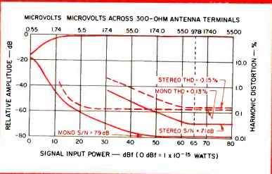
Fig. 1
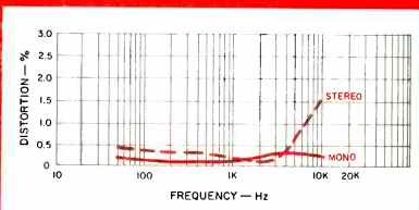
Fig. 2
FM Tuner Section Measurements
Usable sensitivity measured 1.7 µV (10 dBf) in mono, exactly as claimed, but since stereo switching did not take place until an input signal strength of 18 µV (30.3 dBf) was applied to the antenna terminals, we would have to call that the "usable sensitivity" in stereo. The 50-dB quieting point was reached with an input signal strength of as little as 2.1 µV (11.6 dBf) in mono, but required a rather high input level of 47 µV (36.6 dBf) for the same degree of quieting in stereo.
Ultimate S/N in mono was an impressive 79 dB; 71 dB in stereo. Figure 1 shows the mono and stereo quieting characteristics of the FM section as well as the harmonic distortion values for a 1-kHz modulating signal with increasing signal strength. For 65-dBf inputs, THD was a low 0.13 percent in mono; 0.15 percent in stereo. We did note that THD increases rather rapidly as one approaches full modulation and, by backing off on the modulation just a few kHz, both mono and stereo THD dipped below 0.1 percent for mid frequencies.
A plot of distortion versus frequency of modulation is shown in Fig. 2, and the rising distortion characteristic in stereo for higher frequencies was largely due to the presence of visible and audible "beats" at those high frequencies between the pilot-carrier and the test frequency. Muting level was set by the manufacturer at a low 1.5 µV (8.7 dBf). For the three required test frequencies used to check separation, we measured 45 dB at 1 kHz, 42 dB at 100 Hz, and 30 dB at 10 kHz. A complete graphic plot of separation versus frequency was made using our spectrum analyzer's own signal (sweeping from 20 Hz to 20 kHz) to modulate the signal generator and is reproduced in the 'scope photo of Fig. 3. This plot (which includes the 75 microsecond roll-off characteristic) also shows that the 19-kHz notch filter, used to suppress sub carrier products at the output, begins to act too early within the audio band, resulting in a 10-kHz output which is nearly 5 dB more attenuated than it should be. From the appearance of the plot, we suspect that the values chosen for the 75 microsecond network are probably a bit off, since roll-off begins at too low a frequency. Of course, one could easily boost the treble control somewhat in actual listening to compensate for this frequency response discrepancy in FM. Capture ratio measured 1.7 dB, a little bit poorer than the 1.5 dB claimed, but image, i.f., and spurious response rejections were all exactly as claimed, and AM suppression measured 57 dB as opposed to 55 dB claimed. Sub-carrier rejection measured 64 dB, high enough so as to preclude any problems when recording FM programs onto cassette tape decks not equipped with appropriate MPX filtering circuits.
The AM tuner section was found to be typical of its breed, with sensitivity measured as 25 µV (external antenna), signal-to-noise ratio readings of 48 dB (for a 1 mV signal input), and image and i.f. rejection both measuring close to the 45 dB claimed. Selectivity measured 28 dB instead of 30 dB.
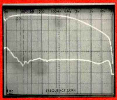
Fig. 3-Stereo FM separation.
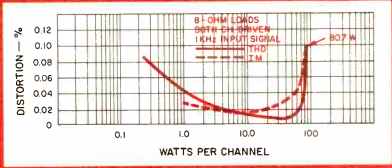
Fig. 4
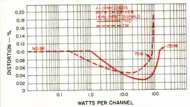
Fig. 5
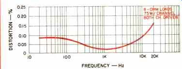
Fig. 6
Amplifier Measurements
Using 8-ohm resistive loads, the amplifier section of the Mark IVB delivered 80.7 watts of continuous power per channel before rated THD of 0.1 percent was reached. At rated output (75 watts per channel), THD was only 0.025 percent for a 1-kHz input signal, while IM measured 0.055 at that output level. Since the Project/One receiver does offer a published specification for 4-ohm load operation, we measured performance under that load condition as well. Power output for rated THD (0.1 percent) measured a gigantic 150 watts, with THD readings for the rated 95 watts per channel level a mere 0.064 percent. Under these load conditions, however, IM distortion reached its rated value of 0.1 percent with only 75 watts of output per channel and increased to 0.19 percent for the rated 95 watts per channel output. Of mild concern to us was the fact that only the left channel met spec at 20 kHz, measuring 0.09 percent THD versus 1.6 percent THD for the right. Power output for a 1-kHz signal and for an IM test signal versus distortion is shown for the 8-ohm load conditions in Fig. 4, and the same results are plotted for 4-ohm operation in Fig. 5. Damping factor measured 55 at mid frequencies, decreasing to 35 at 20 Hz. A graph of distortion versus frequency for full rated output (75 watts into 8 ohm loads) is plotted in Fig. 6.
As for the phono preamplifier section, we measured an input sensitivity of 2.3 mV via either the Phono-1 or Phono-2 inputs and overload capability was 150 mV, better than the 130 mV claimed. RIAA response from 30 Hz to 15 kHz was off by no more than ±0.5 dB as compared with the 1.0 dB tolerance claimed. Beginning with this test report, we are able to show RIAA response graphically on our spectrum analyzer, thanks to an accurately calibrated inverse RIAA network built into the new Sound Technology stereo test panel Model 1200A which now serves as an interface for our other ST test instruments and our viewing oscilloscope. These results are shown in the 'scope photo of Fig. 7.
A-weighted signal-to-noise ratio in phono measured 70 dB (referenced to actual input sensitivity), while for the high level inputs (AUX or tape), SAN referred to the rated output of 75 watts was -89dB. Residual noise was 98 dB below rated output (with master volume control at minimum). Range of control of the bass, midrange, and treble tone controls is plotted in the 'scope photo of Fig. 8, where each vertical box represents an amplitude of 10 dB. The high- and low-cut filters behaved pretty much as claimed, and we do consider the availability of two cut-off points for both of these filters to be a useful feature. In the case of the low-cut circuits, the action of the 15-Hz cut-off setting is barely visible in Fig. 9 since our sweep extends only from 20 Hz upwards to 20 kHz.
We were somewhat puzzled by the response curves obtained using the loudness control feature of the Mark IVB with various settings of the master volume control. As can be seen from the plots of Fig. 10, treble compensation of this loudness circuit actually is greater than the boost afforded in the bass region. This is disturbing since many audio experts maintain that no treble boost at all is required at the treble end or very little at most. We suspect that the designers of this circuit provided such extreme emphasis so that the listener would definitely "detect a big difference" when the loudness switch is activated.
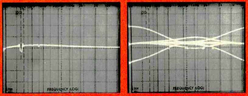
(left) Fig. 7-Overall frequency response. (right) Fig. 8-The bass, midrange,
and treble control range with the Project! One Mark IVB receiver.
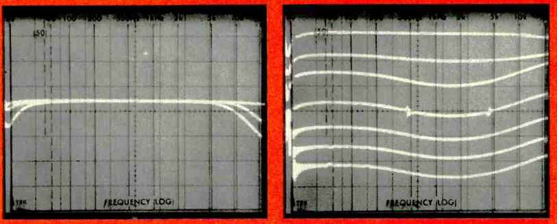
Fig. 9; Fig. 10
Listening and Use Tests
The aforementioned Sound Technology stereo test panel has the unusual capability of permitting a tester to switch directly from load resistors to our lab monitoring speakers at the push of a button. This now gives us the opportunity to audibly evaluate what is going on during static bench testing of audio equipment in addition to listening tests which are conducted at our leisure after bench testing has been completed (often, for several days afterwards). In any event, the FM section exhibited good sensitivity and quieting in both forms of listening tests and pulled in just about all of the stations by which we audibly judge such things as sensitivity and quieting ability. The stereo switching threshold is, in our opinion, set at too high a level which prevented us from receiving some weak-signal stereo transmissions which are normally heard in stereo on other receivers. FM calibration was off by-150 kHz at 98 MHz and by +100 kHz at the high end of the dial and, as we might have guessed, FM lacked a certain amount of high-end brilliance which had to be compensated for by means of the treble control to equalize for the premature roll-off discussed earlier. The limitations imposed by the increased distortion with increasing modulation only became apparent for stations which habitually over-modulate (and served to disclose which stations in our area are at fault in this regard!). Phono performance was quite good, with no evidence of overload distortion, even on heavily recorded passages, and what seemed to be a good interface between the cartridge and input stages. The amplifier section seems to strain a bit as very loud volume levels are approached, but is quickly tamed by backing off a bit on the master volume control. The use of medium- to high-efficiency speakers should enable the owner of this receiver to attain quite satisfactory listening levels even in large listening rooms, however.
Obviously, one of the chief purposes of a retail chain in creating its own line products is to be able to offer such products at highly competitive prices. (After all, one degree of price mark-up is eliminated in such arrangements between a retailer and a prime manufacturer.) On that basis, the people at Playback have met with success. The Mark IVB compares very favorably with receivers costing more than its suggested retail price.
--Leonard Feldman
(Source: Audio magazine, Apr. 1978 )
= = = =