by Dr. Toshi T. Doi
[Dr. Toshi T. Doi is Deputy General Manager of Sony Corporation's Digital Audio Division, Communications Products Group, in Tokyo, Japan.]

This article is excerpted from a paper presented to the 73rd Convention of the Audio Engineering Society, held March 15-18, 1983, in Eindhoven, The Netherlands. Copies of the preprint, No. 1991 (84), may be obtained from the AES, 60 East 42nd St., New York, N.Y. 10165.
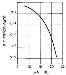
Fig. 1--Bit error rate vs. S/N for peak-to-peak signal and rms noise values.
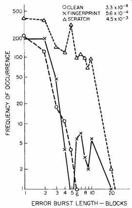
Fig. 2--Typical block-error statistics for an optical disc when clean (3.3
x 10^-4 ), with fingerprints (5.6 x 10^-4, and scratched (4.5 x 10^-3). Figures
shown are for a disc with a linear speed of 1.2 meters per second, bit rate
of 2.352 Mb/S, and block length of 160 bits.
Error correction is one of the key technologies in the field of digital audio, and I believe that the basis for error correction can be plainly explained by use of a "supermarket shopping" model, which I will develop.
There are various criteria for any error-correction code which is to be incorporated in a digital audio system, and I will give some details on the various code systems and pay special attention to the Electronic Industries Association of Japan (EIAJ) format for the Compact Disc. This format is called cross interleaving and it is a unique method of combining two codes by interleaving delay. In practice, it has proven very efficient in performance as well as highly economical in hardware design. Because of these two qualities, the method has been applied to many other systems beyond the Compact Disc system.
One good way to understand the history of digital audio is to look at the progress of error-correction technology. The error-correction codes them selves have been well studied by the coding theorists, but their application to digital audio recording is not so straightforward. So far, great effort has been paid to the study of the criteria necessary for truly reliable systems in studio or home, the investigation of the causes and the statistics of errors on magnetic tapes and discs, the practical and the theoretical approaches to the design of error-correction codes, achieving a better trade-off between performance and hardware cost, and good, easily implemented hardware designs as well.
Basically, error-correction codes can be categorized as linear versus nonlinear, block versus convolutional, and word-oriented versus bit-oriented.
In digital audio recording, a combi nation of linear, block, and word-oriented coding methods has generally been adopted. The cross-interleave method, however, is an exception since it uses a block code in a convolutional structure in its application to the Compact Disc. In this way, the higher performance of a convolutional structure can be enjoyed while still keeping within the simple structure of block coding. There are three basic reasons why a word-oriented code is used. First, it has better correction capabilities for burst errors. Second, memory handling is simpler when RAM is used. Last, the digital audio system handles code words of 16 bits per sample, and it is simpler to design error-correction hardware for 8- or 16-bit words.
Causes of Digital Coding Errors
There is a large variety of ways in which coding errors can occur, but they can be grouped according to where they occur. Code errors occur during digital recording because of:
1. Defects in the tapes or discs which occur during production;
2. Dust, scratches, and finger prints which occur while the media is in use;
3. Fluctuations or irregularities in the recording or reproducing mechanisms;
4. Fluctuation of the level of the reproduced signal;
5. Jitter, wow, and flutter;
6. Noise, and
7. Intersymbol interference.
There are several defects which occur with magnetic tape, and these are:
8. Dust and scratches occurring during production;
9. Defects of scraping of magnetic materials, including traces of dust;
10. Irregularity of tape edge or width, and
11. Trace of a step at the junction between magnetic tape and the tape leader.
Other causes of error are found with the optical disc, and these are:
12. Defects in the photo-resist;
13. Dust and scratches which occur during cutting, developing, plating or pressing;
14. Inappropriate strength of the writing beam or length of the development time, either of which will result in asymmetry of the pits;
15. Error in forming the pits in either plating or pressing of the discs;
16. Bubbles, irregular refraction or other defects in the transparent disc body;
17. Defects in the relative metal coating, and
18. Irregularity of the back surface of the stamper or of the mother.
It should be noted that item 2 also includes damage to the edge of a tape, while item 3 refers to mistracking or mis-focusing (in the case of optical discs), an unlocked servo or to fluctuations in the contact between the tape and the head. Items 4 and 5 are mainly caused by item 3, and it should be noted that a small vibration of tape or head causes a great problem because the recorded wavelength is so short.
The relationship between error rate and noise, item 6, is shown in Fig. 1.
Item 7, the intersymbol interference, is caused by the bandwidth limitation and by the nonlinearity of the recording media.
If a bit error does not have any correlation with other bit errors, it is called a random-bit error. When errors occur in a group of bits, it is called a burst error.
Errors can also occur in words or in blocks, and random (word or block) errors and burst (word or block) errors can be defined in a similar way.
Among the causes of error described, items 1, 2, 3 and 4 correspond to a long burst error, and 5, 6, and 7 to a random or short burst error. In actual digital audio recordings, all kinds of error are mixed together, and the code should be designed to cope with any combination of random, short burst, or long burst errors.
Error Measurement
Measuring the meaningful error characteristics of digital audio recording media is not an easy task. In the early days, word errors were directly measured, and optimization of an error-correcting scheme was carried out based on the obtained statistical data.
The approach was theoretically reasonable, but a real working system may not always represent the proto type system. Moreover, the complete system may not be available during the process of system design.
Here, the most important point is to be able to recover from such accidents as tape damage, fingerprints, scratches and so on. The system should be designed to obtain a block-error rate better than, for instance, 10^-4, so as to guarantee that the error rate is sufficiently low after the correction in the normal condition.
Defining the tolerable level of accidents is the most important point in designing error-correction schemes, and this greatly depends on the structure of the recording media. Cassette tapes, open-reel tapes, and optical discs must be handled completely differently in this sense. Figure 2 shows one of the typical examples of optical discs measured under the following three conditions:
1. A clean disc, in its normal condition, with a block-error rate of 3.3 x 10^-4;
2. A fingerprinted disc, where fingerprints are located all over the disc, with a block-error rate of 5.6 x 10^-4, or
3. A scratched disc, where the disc has been rubbed on a wooden table for approximately one minute, with a block-error rate of 4.5 x 10^-3.
In the case of these accidents, long burst errors are observed, and there fore it is recommended that errors be measured by block, rather than by bit.
Error Detection
Use of a parity check bit is well known as a simple error-detection scheme, and it detects 100% of even-numbered errors. This ability is not sufficient for most digital audio recordings, and therefore Cyclic Redundancy Check Code (CRCC) is commonly used for error correction. The basis on which to decide the length of the block always poses a question, and the larger block seems better because it keeps the same detection capability with less redundancy. But if the system tends to encounter random or short burst errors frequently enough, as with optical discs, then the resulting error rate with longer block length may worsen considerably. Moreover, even one bit error in a long block deteriorates the whole block. There also exists a trade-off between redundancy and the safety margin, where the latter depends on the error-correction strategy after detection. CRCC is often used as an "error pointer" in error-correction codes, and the detectability of errors should be analyzed before designing the whole correcting scheme.
Principles of Error Correction
Figure 3 shows a typical supermarket shopping receipt (Slip A), listing the prices of four items (W1, W2, W3 and W4) and their total (P). The "syndrome" (S) is calculated for checking; when there is no error, S = 0.
In Slip B, the price of W2 is missing (W2* = 0). The missing data word is called an erasure, and the correction is very simple, as shown. Slip C contains a one-word error in W2; the values of all the words (W1, W2, W3, and W4) and the total P are now uncertain, and they are marked with an accent. As the value of the Syndrome S is not zero, it is known that an error occurred, but that error cannot be corrected with just the information available.
In Slip D, we have the same error in W2, but the erroneous word is now pointed out by an error pointer. The correction in this case, which is called pointer-erasure correction, is exactly the same as for erasure.
The code in Fig. 3 is a block code with four data words and one check word. The code is capable of one word-error correction and one erasure correction, but error correction is impossible.
In the actual codes used in digital audio recordings, a parity word of modulo-two (exclusive-or) is normally used for erasure correction, instead of the total value P in Fig. 3, and CRCC is used for the error pointer.
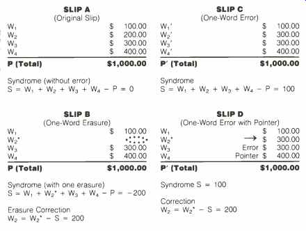
Fig. 3-"Supermarket receipts" as examples of single-erasure correction.
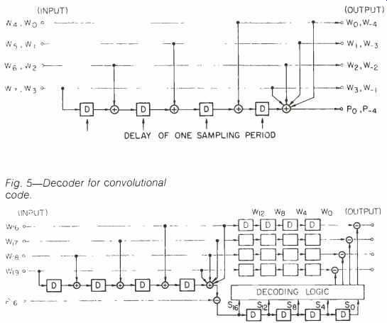
Fig. 4-Encoder for convolutional code.

Fig. 5-Decoder for convolutional code.
Convolutional Code
The examples shown in the previous section are all classified as block codes, where the encoding is completed within the block. Figure 4 shows an example of an encoder of convolutional code, where D means a delay of one word. (Editor's Note: D can also mean the distance between any two words, though this is not discussed here.) The check words are generated once after every four words of data, and each check word is affected by the previous eight input words. The decoder is shown in Fig. 5.
The redundancy for this code is the same as that of the code in Fig. 3, but the error-correction capability is superior. This is because the number of related syndromes for each error is bigger in the case of convolutional code due to the convolutional structure.
On the other hand, once an uncorrectable error occurs, it would affect the syndromes long after the error passes away, and the number of resulting errors in the decoded sequence becomes longer. This is called error propagation.
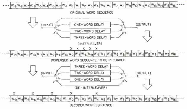
Fig. 6-Interleaving and de-interleaving. Note dispersion of burst error in
decoded word sequence.

Fig. 7-Encoder for cross-interleave method; original data words = k; check
words for C, and C2 = R, and R2; total check words = R, + R2; redundancy =
(R, + R2) / (k + R, + R2).
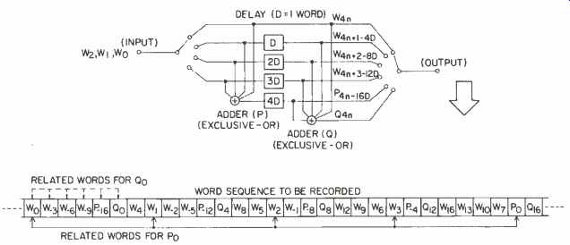
Fig. 8-Encoder for C/C method.
Interleaving
Interleaving is a way to disperse the original sequence of bits or words into a different sequence; the reverse is called de-interleaving. Figure 6 shows a simple delay interleave. A burst error which might occur during playback is converted into random errors by de-interleaving. Such interleaving is often used with a block code to increase burst-error correctability. If all the words related to the original code block are dispersed to every sixth word, a burst error of up to six words can be corrected if an appropriate error pointer is provided. A combination of double-erasure correction code, interleave, and CRCC for an error pointer was adopted for the Electronic Indus tries Association of Japan (EIAJ) for mat for home-use digital tape recorders. (Editor's Note: The EIAJ has also just announced agreement on a video format for use on CD).
Cross-Interleave Method
When two block codes are arranged two-dimensionally so that their rows and columns form a big block, the resulting code is called a "product code." The cross-interleave method falls into the class of product codes, but it is distinguished from the conventional one by its interleaved structure.
The cross-interleave method is a combination of two or more block codes which are separated from each other by delay for interleaving. In this case, the final correctability is sometimes better than that of conventional product codes, owing to the convolutional structure. Figure 7 shows the general form of the cross-interleave method. At the decoder, the syndromes of one code can be used as the error pointer for another code, and CRCC for error detection can be omitted in erasure correction. It is also possible to arrange the third block code after another delay interleave.
In Compact Disc format, the two block codes selected are Reed-Solomon codes and are named CIRC (Cross Interleave Reed-Solomon Code). When both codes selected are single-erasure correction codes, the code is called cross-interleave code (010). (Editor's Note: Reed and Solomon are the inventors of a powerful and widely used class of codes.)
Figure 8 shows a simple example of a CIC encoder where a single-erasure correcting code is added after the delay for interleaving, generating the check words P and O. The correctability of CIC depends on the number of decoding steps, and one-step decoding is as good as single-erasure correction; thus, the correction capability increases as the number of steps in creases. Figure 9 shows the correction capability plotted versus the number of decoding steps.
Error Concealment
When error exceeds the ability of the code to correct, the uncorrected words should be concealed. Figure 10 shows the noise power induced by various interpolation methods when they are applied to a pure tone signal with uncorrectable errors. The methods of concealment shown here are as follows:
1. Muting is where the value of the erroneous word is always set to zero;
2. Zero-order interpolation is where the previous value is held over;
3. First-order interpolation is where the erroneous word is replaced with the mean value of the previous and the next word, and
4. Nth-order interpolation is where a polynomial is used to generate a re placement for the erroneous word, in stead of the first order.
In most systems now in use, a combination of 2 and 3 is used. If all the erroneous words have errorless words as neighbors, then 3 is applied. For consecutive word errors, method 2 would be applied, with the final erroneous word interpolated by method 3. It is also well known that a better interpolation is possible by use of an appropriate digital filter. Subjective tests show that the length of error does not greatly affect the perception as long as all interpolated words are neighbored by words without error.
Evaluation of Error-Correcting Schemes
In the application to actual error-correction systems, the above methods are mixed, and the scheme is optimized to suit the particular system either by computer simulation or by trial and error. The most important point in designing the coding scheme is, there fore, to set the criteria for the performance of the code. Some of the criteria are as follows:
1. Probability of misdetection;
2. Maximum burst error to be corrected;
3. Maximum burst error to be concealed;
4. Correctability of random error;
5. Correctability for the mixture of random, short burst and long burst error;
6. Guard space;
7. Error propagation;
8. Block size or constraint length;
9. Redundancy;
10. Ability for editing;
11. Delay for encoding and decoding, and
12. Cost and complexity of the en coder and decoder.
For most digital audio systems, errors exceeding the correctability of the code are designed to be concealed.
Therefore, the most important item is the probability of misdetection (1). The mis-detected error cannot be concealed and results in an unpleasant click noise from the speakers. This should not occur even in worst-case accidents. Items 2 and 3 taken together represent the strength of the system against burst errors.
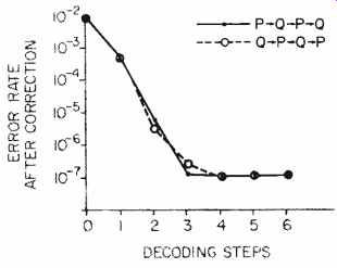
Fig. 9--How the number of decoding steps affects random word-error correctability,
using C/C. (One block = 6 data words + 2 check words; word error rate [PW]
= 10^-2.)
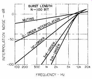
Fig. 10--Noise power for various interpolation methods applied to a pure-tone
signal with uncorrectable errors (see text).
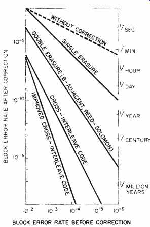
Fig. 11--Random block-error correctability for various codes (1 block = 288
bits).
Table I gives some examples of the burst-error correction and concealment for CD and other formats. In each case, the length of concealment is designed considerably longer than that of the correction. CD is strong against fingerprints because the thick transparent layer (1.2 mm) between signal pits and the surface nullifies their effect.
The burst-error correcting capability is mainly determined by delays if inter leaving is used with the correcting code. The correction or concealment length should be evaluated as a function of the memory size required.
Figure 11 shows the correctability of various codes against random block error, where one block consists of 288 bits. The block length is supposed to be long enough for even a short burst error to be treated as a random block error. Initially, the evaluation shown in Fig. 11 was considered appropriate, but it was found not to coincide with experience in studio environments.
Machines installed in studios showed much more frequent miscorrection than indicated by these values. The reasons were that the tapes were not always new, that dust and fingerprints were more severe in the studio environment, and that the machines were not always tuned properly. Therefore, evaluations made using a mixture of random, short burst and long burst errors proves to be much more realistic.

Table 1--Burst-error correction and concealment.
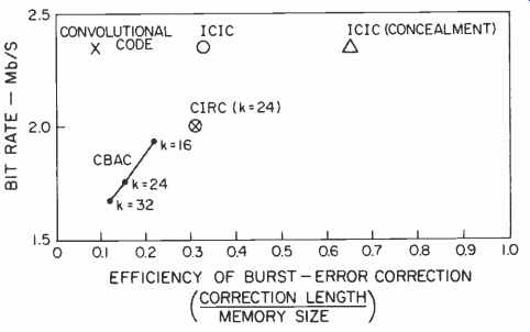
Fig. 13--Burst-error correction vs. bit rate for several codes.
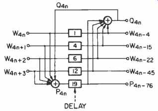
Fig. 12--An ICIC encoder. ("W" codes are data words; "P" and "Q" codes
are error-correction words.)
Error Correction on the CD
Among the causes of error on optical discs, the effects of fingerprints, scratches or dust are not so different from those in magnetic tapes. There fore, it is sufficient if the error-correction scheme enables correction of a long burst error with reasonably small guard space.
On the other hand, causes 12 through 18, described at the beginning of this article, have the tendency to produce random or short burst errors.
In addition, there is a possibility of producing random or short burst errors by mis-focusing and tracking offset, which may deteriorate the frequency characteristics and signal-to-noise ratio.
The study started from the comparison between the ICIC (Fig. 12) and a newly developed convolutional code.
The ICIC has the ability to correct an arbitrary five-word error, while the convolutional code can correct up to two symbols (words). Both codes are de signed with the same redundancy to obtain a bit rate of 2.35 Mb/S. Both performed very well for normal discs with average fingerprints and scratches. It was found that the burst-error correction was better with the ICIC because the correctable length is three times longer than with the convolutional code, and if concealment is considered the goal, it becomes more than seven times (see Fig. 13).
Conclusion
The fundamentals of error correction and its application to digital audio re cording systems have been de scribed, with the stress of the explanation laid on the practical side, omitting overly detailed theoretical considerations. The cross-interleaving method discussed here is now widely used in the field of digital audio because of its simplicity and efficiency.
Looking back to the short history of error-correction code applied to digital audio recording, remarkable progress has been made with high enough performance and relatively low redundancy. Further progress will be necessary when the packing density increases and high error-rate recording systems are introduced.
One of these applications will be the domestic digital cassette recorder, which is expected to become competitive to the conventional analog cassette in size and playing time, while attaining high performance equivalent to that of the Compact Disc.
Also see: Philips Oversampling System for Compact Disc Decoding (April 1984)
(adapted from Audio magazine, Apr 1984)
= = = =