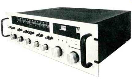
MANUFACTURER'S SPECIFICATIONS:
FM Tuner Section:
IHF Sensitivity: 1.8 uV.
Quieting Slope: 6 uV for 60 dB quieting.
Selectivity: 70 dB.
Frequency Response: 30 Hz to 15 kHz, + 1 dB.
THD: mono, 0.3%; stereo, 0.5%.
S/N Ratio: 70 dB.
Image Rejection: 100 dB.
I.F. Rejection: 100 dB.
Capture Ratio: 1.5 dB.
AM Tuner Section:
IHF Sensitivity: 15 µV (external antenna).
Selectivity: 40 dB.
S/N Ratio: 50 dB.
Image Rejection: 75 dB. I.F.
Rejection: 75 dB.
Amplifier Section:
Power output: 54 watts per channel from 20 to 20,000 Hz into either 4- or 8-ohm loads, at maximum harmonic distortion of 0.3%.
IM Distortion: 0.2%.
Input Sensitivity: Phono 1, 2.2 mV; Phono 2, 4.0 mV; AUX 1,2, and Tape, 115 mV.
Frequency Response:
Phono, RIAA ± 0.5 dB.
Phono Overload: 125 mV.
S/N Ratio: Phono, 65 dB; AUX and Tape, 75 dB. Residual Noise: 1.5 mV.
Low Filter:-10 dB at 20 Hz.
High Filter:-10 dB at 10 kHz.
General Specifications:
Dimensions: 19 in. W. x 5 1/4 in. H. x 17 in. D. (including rack handles, AM antenna extended). Weight: 38 lbs.
Price: $600.00.

Fig. 1 Rear view of receiver.
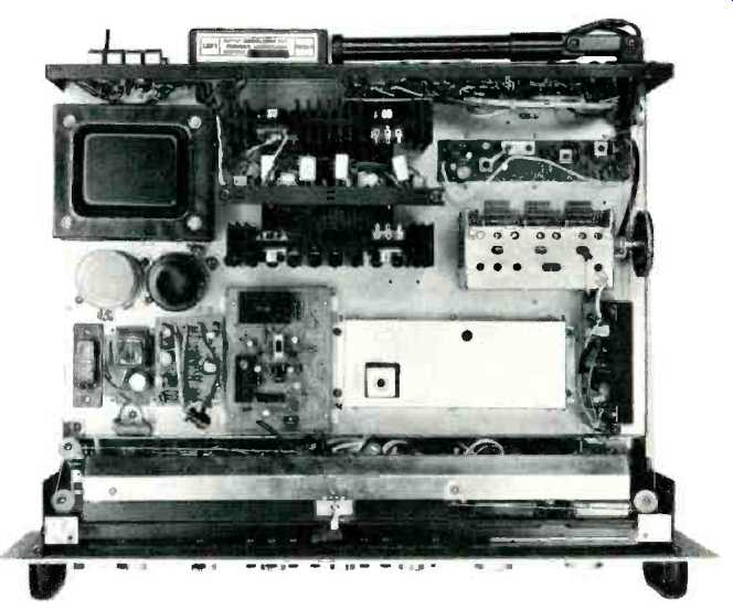
Fig. 2 Internal view.
C/M Laboratories of Norwalk, Connecticut, first entered the component high fidelity field some years ago with what were then state-of-the art, basic amplifiers and preamplifiers whose performance and quality was universally acclaimed by the audio fraternity. Many of those early pre amps and amps found their way into professional applications, and the name CM Labs has been associated with the superior equipment often found between consumer components and studio-grade equipment. More recently, the company has decided to strengthen its spot in the consumer market by importing consumer products from abroad, and by serving as the sole distributor of recognized high-end products manufactured by others but designed to C/M's exacting standards. Included in the C/M group are Cambridge Audio electronic and speaker system components, LWE speaker systems, and now a line of receivers which includes the Model RR805, a relatively high-powered unit suitable for rack mounting or for installation in an optional wooden cabinet.
The front-panel layout clearly demonstrates that a "professional" look need not be esthetically unappealing in home situations. Major controls are located along the bottom of the panel and include dual-concentric Bass and Treble tone controls, a Mode switch (for Left-only, Right only, Stereo, Reverse, and L+R), a six-position Program selector, Balance control, Master Level control, and flywheel-coupled Tuning knob. These last two controls use larger-sized knobs for easier grip. A row of 12 push buttons along the center section of the panel takes care of the control functions, Power on/off, panel-light dimming, Speaker selection ( Main or Remote), Loudness compensation on/off, high- and low-cut filters, a pair of Tape Monitor circuits, tone-control defeat, and Audio and FM Muting. To the right of these buttons are six tiny lights which indicate the program source selected.
Two normally blacked-out areas of the panel become illuminated only when AM or FM is selected. A linear FM dial scale, a 0-100 logging scale, and an AM frequency scale are then visible, illuminated in soft green, in the larger of the two areas, while the smaller cut-out area to the right discloses signal-strength and center-of-channel tuning meters on either side of the usual stereo indicator light, an LED in this case.
The rear of the unit, pictured in Fig. 1, contains twin pairs of Phono and AUX input terminals, jacks for Tape Monitoring (paralleled by DIN sockets), screw terminals for 300 ohm, 75-ohm, and AM antenna connections, and jumpered Main Amp In/Preamp Out jacks for, each channel. Speaker connections are made via spring-loaded terminals, which require only that stripped ends of speaker wires be inserted in appropriate small holes which appear when each "key" is depressed. There are individual speaker-line fuses as well as a power-line fuse and a pair of switched a.c. convenience receptacles.
An interesting "first" (for us) is the inclusion of a pair of six-terminal sockets which are identified in the owner's manual as "output connections for feedback loudspeaker systems." LWE speakers systems (now handled by C/M Labs) employ motional feedback and require internal connection to circuit points inside the amplifier with which they are to be used. C/M apparently felt that this requirement discouraged prospective users of these speakers in the past, since few audio buffs have both the technical skill and inclination to get at the innards of their components. By providing these sockets externally, CM will no doubt en courage sales of these companion products. A fully-pivot able AM ferrite antenna completes the rear panel layout.
Figure 2 shows the internal layout of the receiver. Uncluttered in appearance, the receiver's most prominent components are the heat sinks on which the four output transistors are affixed. Two of these output devices have thermal sensing elements, and there is an additional circuit protecting relay which delays turn-on for a second or two after the power button is depressed. Current limiting is not employed, since the designers of the RR805 maintain that it audibly affects performance at high listening levels. One executive of the firm told us, "Our current-limiting circuit consists of two, good, old, reliable speaker-line fuses!" While no schematic diagram was supplied with our sample, the rather brief preliminary operating instruction booklet spelled out the use of differential amplifier circuitry, and it was obvious from the power-supply configuration and dual filter capacitors that the output circuitry is the direct-coupled type. The driver boards plug in, and may be easily removed for servicing. A four-gang variable capacitor is used in the FM front-end, which is a fully-sealed, separate unit. The i.f. section is also fully shielded, and the stereo multiplex section employs a modified form of phase lock-loop circuit which requires adjustment of two tuned circuits, as compared with the more usual type which needs adjustment of only a single potentiometer. While the IC equipped FM i.f. section uses fixed-tuned, solid-state filters, the AM i.f. section employs the conventional interstage transformers and a three-gang variable capacitor.
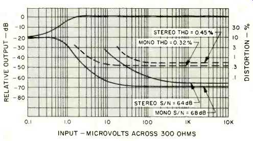
Fig. 3--FM quieting and distortion characteristics.
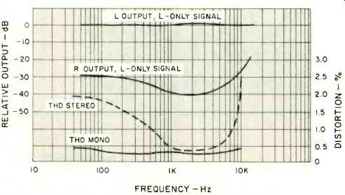
Fig. 4--FM separation and distortion versus frequency.
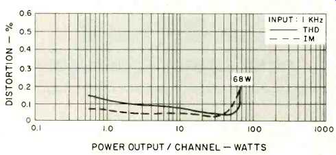
Fig. 5--Harmonic and intermodulation distortion versus power output.
Tuner Section Measurements
The FM quieting slope of the RR805 is so steep that 50 dB of quieting is reached with a mere 2.5 µV of signal input in mono. Between 6 and 7µV produces 60 dB of quieting, though ultimate S/N ratio reached only 68 dB instead of the 70 dB claimed (see Fig. 3). Residual noise measured is not strictly speaking noise at all, but rather a bit of residual hum which at the-68 dB level from 100% modulation has far less audible effect than might be indicated by the -68 dB number alone. If C/M can eliminate this bit of 60 and 120 Hertz hum, our 'scope observations indicate that actual noise might well measure closer to -75 dB. IHF sensitivity in mono measured exactly 1.8 µV as claimed. In stereo, however, automatic switching did not take place until an input signal strength of 18 µV was reached, and there was a transitional region between 10 µV and 20 µV during which reception was "half way" between mono and stereo. The same appeared true of the muting circuit. Muting threshold defeat took place at about 18 µV, and from 10 to 18 µV the muting circuit was half-activated, producing a fair amount of distortion. We suggest that anyone receiving marginally weak signals with this receiver would be better off disabling the muting with the pushbutton provided.
Harmonic distortion in mono measured 0.3% at mid band frequencies, as claimed, while in stereo, THD was 0.45%, a bit better than the 0.5% claimed. THD at other frequencies is plotted in Fig. 4. Distortion remained well under 0.5% for all significant frequencies in mono but tended to rise at the low- and high-frequency extremes in the stereo mode. Separation in stereo FM was 40 dB at mid frequencies, as claimed, decreasing to 30 dB at the low end and to about 28 dB at 10kHz.
Capture ratio measured 1.5 dB, as specified, while i.f. and image rejection were 90 dB and over 100 dB respectively.
Selectivity measured just over the 70 dB claimed, but we are at a loss to understand the adjacent-channel specification listed in the C/M booklet. It states that adjacent channel rejection is 100 dB either a misprint or a copywriter's goof.
Obviously, if alternate channel selectivity is 70 dB, adjacent channel selectivity (which is the same as adjacent channel rejection and not presently a specification which needs to be published) cannot be any greater! Better print some new literature, C/M! AM specifications were generally met, though we suspect that C/M engineers may be measuring i.f. rejection at some frequency other than 600 kHz, since at that frequency it came nowhere near the 75 dB claimed. Distortion at 30% modulation was 1.3% on AM.
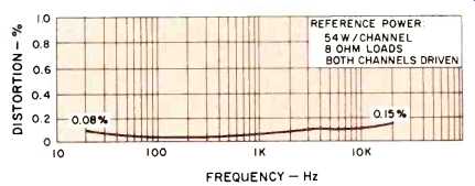
Fig. 6--Distortion versus frequency.
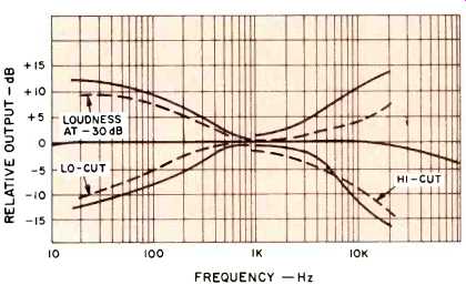
Fig. 7--Tone-control range, and filter and compensation characteristics.
Amplifier Measurements
If the RR805's tuner section may be regarded as good (and it is), then the amplifier section should be described as superb. It is conservatively rated, even in terms of FTC requirements. It delivered nearly 70 watts of power at mid-frequencies for the rated THD of 0.2%, as plotted in Fig. 5. IM distortion at normal listening levels was even lower than THD, reaching the rated 0.2% level at precisely the same power output as was the case for THD, 70 watts. At nominal 10-watt levels, THD was a low 0.082%, while at wideband rated power (54 watts per channel), THD was 0.041% at 1 kHz.
Figure 6 discloses that C/M might well have rated the amplifier at more than 54 watts per channel over the spectrum from 20 Hz to 20,000 Hz, since at that power level, THD measured only 0.08% at 20 Hz (the usual limiting frequency for all such measurements) and 0.15% at the high frequency extreme of the audio band.
The measured preamplifier and control characteristics were excellent too. Optional signal input sensitivity (2.2 mV for the Phono 1 inputs and 4.0 mV for Phono 2) is a welcome feature in view of the rather wide range of outputs available from currently-popular phono cartridges. Of course, this approach rules out the use of two turntable systems equipped with identical cartridges if equal gain is desired from each. Overload distortion occurred at 145 mV for both phono inputs, somewhat better than the 125 mV claimed by the manufacturer, and RIAA equalization was within 0.25 dB from 50 Hz to 20 kHz and was within the stated 0.5 dB down to 30 Hz. Frequency response from high-level inputs to amplifier output, with tone controls set either flat or defeated was within 1 dB from 5 Hz to 20 kHz and within 3 dB from 3 Hz to 90 kHz, indicating that C/M engineers subscribe to the "extra wideband response" philosophy of audio amplifier design. Hum and noise was down 62 dB with respect to input sensitivity for Phono 1 (referred to full power output); 66 dB with respect to the Phono 2 inputs. AUX- and Tape-input hum and noise was 73 dB below full output, referred to nominal 115 mV input sensitivity for these high-level input positions. Residual noise was 83 dB below full output, which corresponds almost exactly to the 1.5 mV of residual noise claimed by the manufacturer.
Figure 7 shows the range of bass and treble tone-control action as well as filter and loudness compensation characteristics. Both low- and high-cut filters have a 6 db-per octave slope which, in itself, is not objectionable. However the cut-off points for the filters are set too close to the mid band and thus they are not much more effective than the already-available tone controls. Loudness compensation at the -30 dB setting of the master Level control is also plotted in Fig. 7 and affects high-end as well as low-end response.
Listening Tests
The RR805 was hooked up to a pair of acoustic-suspension speaker systems of medium efficiency and produced highly satisfactory performance in phono and generally creditable results when tuned to our favorite FM stations.
Frequency calibration was accurate in both AM and FM, and the zero-center tuning meter was correctly calibrated to indicate proper tuning at the point of lowest distortion. Played at fairly loud listening levels with peaks just below clipping levels for more than two hours, the unit showed no sign of overheating. The same was true for the FTC one hour preconditioning test at one-third rated power with a fixed frequency input. Clearly, distortion levels as measured for the RR805 are not audible in listening tests, so that most of our subjective evaluation of this receiver's performance had to do with its ruggedness of construction, ease of control function and use, control flexibility and features, adequacy of input and switching facilities and overall reliability. From our encounter with the C/M RR805, we rate the unit high in all these qualities.
--Leonard Feldman
(Source: Audio magazine, Jun. 1975)
Also see: C/M Laboratories Model CM912 power amplifier (June 1975)
= = = =