Author: Edward J. Foster
As I write this article, the new IHF amplifier standard, designated "Standard Methods of Measurement for Audio Amplifiers, IHF-A-202, 1978," is being distributed to the Institute's membership for ratification. As you read this story, the standard will (I hope) have been approved and will be official.
A technical standard can easily be in committee for three years-longer is not unknown-and it has a truly useful life of perhaps three to five years-less is not unknown. Not that a standard will be replaced every few years-producing one is too formidable for such luxury-but technology changes so quickly that, within a short period, new "distortions" are "discovered" and new methods and specifications begin to appear. The uniformity of measurement and specification method, the raison d'etre of a standard, fades, and the clarity of comparison is obscured.
The IHF's previous amplifier standard was promulgated in 1966; the new one will be dated 1978. In that 12-year period, the audio industry grew from adolescence to relative maturity. The engineering fraternity drifted from the 1966 standard, and many incomparable specifications appeared. The IHF's Standards Committee set up a sub-committee to develop a more modern document, and once the FTC's 1974 "power ruling" became law, it was legally impossible to follow the letter of the 1966 document.
The amplifier standards committee first met in February, 1975, called together by Len Feldman, the IHF's Technical Director and head of all the standards committees. Almost three years later, a draft was approved by the IHF Executive Board and distributed to the membership for ratification.
Over most of the period, I was associated with the subcommittee work--for half the time as Chairman.
Our initial hopes that the 1966 document could be revised and edited to bring it into step with the present soon were dashed, and, after struggling for a while with the extant standard, we decided that it would be better to strike out anew.
That is what we did, using the 1966 document as a guideline to help to avoid missing something.
Definitions--Total Harmonic Distortion
To assure that everyone will be "talking the same lingo," an extensive section of definitions was first drafted to serve as the bedrock on which the standard rests. I'll take this opportunity to encourage anyone using the standard to study the definitions carefully as some are surprising. For example, total harmonic distortion is now defined in terms of the square root of the sum of the squares of the individual harmonic components, not as the reading of a conventional distortion analyzer, which also includes residual noise as part of "distortion." Now this is defined separately as THD + N, i.e. total harmonic distortion plus noise.
This is an example of the subtle differences in specifications that a redefinition can make. It is not necessary that every branch of electronics subscribe to our definitions; it is necessary that common definitions be used within the audio industry.
Why change the definition of THD? Mainly because the old definition was a misnomer including, as it did, the contribution of noise as part of distortion. You have seen curves taken on many amplifiers that indicate a greater "distortion" at reduced power levels than at more advanced power levels. In the past, no one could tell whether this increase in "distortion" was due to a notch at the crossover (important) or to residual noise (not important insofar as the noise level is specified separately). By eliminating noise from the THD spec, the ambiguity is removed. And now that spectrum analyzers are available that can distinguish between individual distortion components, the new definition is practical as well as correct.
The widespread use of the spectrum analyzer has made it possible to determine other useful distortion parameters. The new standard provides for the specification of individual harmonic percentages, i.e. the percentage of second harmonic distortion, etc. It is generally agreed that harmonics of higher order are more disturbing than are those of lower order. The standard also provides for the possibility of a "weighted" total harmonic distortion measurement ( W THD) to take this audibility factor into account. However, we don't yet know enough about the audibility of the various harmonics to standardize a weighting algorithm. Thus, the standard allows any algorithm to be used provided that it be made part of the spec.
Providing for the Future
Provisions for future measurements, even if they cannot be standardized now, permeate the 1978 document, as the committee attempted to anticipate future needs and provide sections within the standard that will form the basis of future measurements. It is our hope that IHF-A-202 will be a living document that will allow easier revision. In this way, we hope to keep it current with new technology and to increase its useful life.
In this vein, a definition of transient intermodulation distortion (TIM) is included, although no one method of measurement is specified. Several quasi-standard techniques for determining TIM have been proposed. Each puts a handle on the same physical behavior (or misbehavior) but yields results that are numerically different. Which of the methods yields the most useful results? How does one interpret the figures produced? At present, these questions are not easily answered. At one point, the standard included a specific method for determining TIM. It was, I believe wisely, decided not to incarcerate it in cement. We'd merely cut off future research into this interesting subject.
Intermodulation Distortion
Still on the subject of distortion, two methods are specified for the determination of intermodulation: the old "low-frequency/high-frequency" method that the previous standard endorsed and a new "two-tone" method as well. To distinguish between them, the former is called SMPTE-IM after the Society of Motion Picture and Television Engineers which first standardized it; the second is called IHF-IM. The SMPTE-IM method determines the degree to which a high-frequency tone is amplitude modulated by a low-frequency signal. The IHF standard specifies that the two frequencies shall be 60 Hz and 7000 Hz, the most commonly used (but not universal) pair for this type of measurement.
SMPTE-IM is easily measured with conventional IM analyzers. It provides a convenient means of determining intermodulation as a function of output level. Its Achilles' Heel is that it does not investigate behavior as a function of frequency, hence the desirability of an alternate intermodulation measurement that will do so.
The IHF-IM method also uses two frequencies, but they are to be swept across the audio band at a constant difference in frequency, that is f,-f, will remain the same as f, and f, both move up the spectrum. The standard specifies a difference frequency of 1 kHz and that the mean frequency shall be swept from 2500 Hz (the practical lower limit) to the upper rated band edge of the amplifier. All intermodulation products (up to the fifth order) that lie within the audio band (20 Hz to 20 kHz) will be measured and combined to determine the percentage of IHF-IM. Such a measurement establishes intermodulation as a function of frequency, and the measurement can be repeated at various power levels to yield a series of curves of IM vs. frequency with output level as a parameter.
The IHF-IM method is similar to the CCIR-IM method but takes into account more of the higher order products. The IHF-IM method can be extended into the supersonic region and yield information related to transient intermodulation distortion. Either a spectrum analyzer or swept filter can be used to measure IHF-IM.
Whichever way that the intermodulation distortion is measured, the power level to which it refers is defined in terms of the average power level of a sinusoid of equivalent peak-to-peak amplitude. Although this is not the true power level of the two-tone signal, the power scale so defined is compatible with that used in a THD vs. power measurement.
Rated and Reference Characteristics
One source of confusion that the definitions section of the new standard seeks to relieve is the difference between a rated characteristic and a reference characteristic. The easiest way to keep them straight is to associate a rated characteristic with a specification. Ratings are derived from measurements. They are the numbers that the manufacturer claims are representative of the product's performance. A rating is a single value of a characteristic such as power output, distortion, etc. The ratings may be based upon curves (which may also be shown), but they themselves are the single values that represent the "worst-case" conditions.
A reference characteristic specifies the operating conditions under which the rated characteristic is specified. For example, the input-signal level, the output-signal level, the gain setting, etc. are reference characteristics that specify the conditions under which, say, distortion is rated.
The committee had to make two exceptions to this general rule. The "rated bandwidth" means the frequency range over which the performance of an amplifier is rated in other respects, e.g. power output. And the "rated load" of a power amplifier denotes the load impedance into which the amplifier is designed to operate in order to achieve its other ratings. "Reference bandwidth" and "reference load" would have been better terminology, however, the FTC power-output ruling uses the terminology "rated" and, to comply with the letter of the law, we decided to conform to this unfortunate choice of words.
IHF References
In the past, manufacturers have used a variety of reference points. For example, the signal-to-noise ratio (S/N) of some amplifiers is referenced to the amplifier's rated output level, that is, a S/N of 80 dB meant that the output-noise power is 80 decibels below the maximum output level. Other amplifiers carried a rating referenced to a specific input voltage level. A S/N of 80 dB in this case means that the equivalent input noise voltage is 80 decibels below the input reference level, say 10 mV for a phono input. Although both signal-to-noise ratios have the same numerical value, they are not comparable, and there is no convenient means of translating one into the other.
The usefulness of signal-to-noise ratio referenced to the amplifier's rated-output capability is further jeopardized by the fact that the actual noise power a given figure indicates depends upon the power-output rating. For example, consider two power amps, one rated at 10 watts, the other at 100 watts.
Assume that each has an 80-dB S/N referred to its rated output. The 10-watt amplifier is actually 10 dB quieter than the more powerful amplifier because an output-noise power that is 80 dB below 10 watts is actually 90 dB below 100 watts, the difference between 10 watts and 100 watts being 10 d B. It would appear that amplifiers whose noise level is referenced to a common input level can have their signal-to-noise ratios compared directly provided that the input reference level for the two measurements is the same. Unfortunately, even this isn't necessarily true. The noise level of some amplifiers is measured with the volume control fully advanced, others are measured with the volume control at a different setting. The resulting figures are incomparable, and there is no way to bring them into line.
Interdependent ratings that result from referencing one specification to another and ratings based upon non-standard test conditions result in specifications that cannot be compared. The consumer is faced with having to juggle numbers and with trying to translate each figure to a common reference point. Sometimes this can be achieved; sometimes it cannot.
One of the most important aspects of IHF-A-202 is its specification of standardized reference levels and standardized control settings. The underlying philosophy of the new standard is to rate an amplifier under conditions that simulate typical use.
Standard Test Conditions
The second section of the standard specifies the test conditions under which the amplifier is to be operated. Standardized input and output reference levels have been established.
So have control settings. The input reference levels are 0.5 volt for a line input (AUX, Tape, Tuner, etc.), 5 millivolts (at 1 kHz) for moving-magnet or similar type phono cartridges, and 500 microvolts (also at 1 kHz) for moving-coil-cartridge inputs. These levels are typical of normal listening conditions.
In practice, and on a dynamic basis, the input-signal level may be higher or lower depending upon the instantaneous level of the music.
The output reference levels are 1 watt for a power amplifier and 0.5 volt for a preamplifier-again, roughly the average operating conditions in the home. For the majority of the tests, all tone controls, filters, etc. are defeated (if possible) or they are set to their nominally flat positions. Gain controls are set so that an input of reference level produces an output of reference level.
These reference levels assure that each amplifier is tested under identical operating conditions, regardless of its maximum available gain or its power-output capability. An exception is made for an independent power amplifier. Many do not have a gain control, and it was thought best to test them all under conditions of maximum gain. Most power amplifiers have pretty much the same gain in any event.
Section 2 also standardizes a preamplifier output-load impedance-10,000 ohms in parallel with 1000 pF. The new pre amp output-load impedance represents the approximate worst-case conditions when in use and is much lower in value than that specified in the 1966 standard. A power amplifier is tested with the manufacturer's "rated" load, but an IHF reference-load impedance is specified as 8 ohms nonetheless.
For the first time, standardized input termination impedances are specified-a resistor of 1000 ohms for each line and moving-magnet phono input and 100 ohms for moving coil phono inputs. No longer will amplifiers be rated under zero source impedance (ideal) conditions. Finally, section 2 specifies the characteristics and the accuracy of the test equipment to be used.
Section 3--The Meat of the Standard
The third section details the tests that are to be performed on a single-channel amplifier. It also specifies how a rating is to be derived from the test results. Each subsection of 3.0 outlines the deviations from standard test conditions that are required for the test to be performed properly. By FTC dictate, the first and foremost spec for a power amplifier is the continuous average power output rating (sometimes mislabeled "RMS Power.") Section 3.1 relates to this rating and is in compliance with the FTC ruling as currently interpreted. Enough has been written about this ruling to eliminate the need for repeating it here. The only deviation from the standard test conditions is in the setting of the gain control. For practical reasons, it is adjusted for an extra 12 dB of gain.
Two other points should be noted. For the purposes of the standard, power is defined in terms of a voltage measurement-as the square of the voltage divided by the load impedance. As long as the signal is sinusoidal, and the output and load impedance purely resistive, the figure so calculated is indeed the power in watts. When the impedances are partially or totally reactive, or when the signal being measured is not sinusoidal (for example, residual noise), the calculation from a voltage measurement (with the type of voltmeter specified in the standard) does not yield "true" power.
Nonetheless, we have defined it as such-the reason being that this is, in fact, the way measurements are made. By acknowledging this point in the definitions, we assure that everyone is talking the same language even if it is questionable theoretically. Some committee members (myself included) would have preferred to rate a power amplifier in terms of its voltage and current capabilities into a given load and to avoid the "power" nomenclature entirely. However, the consumer is so used to the concept of power that such a radical change was felt to be unwise. Besides, the FTC ruling is based upon a power measurement.
In the definitions section, provision is made for an alternate logarithmic power scale based upon the decibel; 0 dBW is defined as the equivalent of 1 watt, and, from that reference point, all other power levels can be calculated in the customary manner. A 10-watt power level is equivalent to 10 dBW, a 20-watt level to 13 dBW, a 100-watt level to 20 dBW, etc. Since our sensation of relative loudness is approximately logarithmic, dBW-based ratings correspond more closely to how "loud" the sound is.
Dynamic Headroom
The 1966 standard provided for a "music power" rating that indicated the power level that an amplifier was capable of supplying for a short period of time. Two methods of measurement were specified. One required that the amplifier's power supply be disconnected and replaced by a regulated laboratory supply. Then the continuous power capability (at rated distortion) would be measured. The second method used a modified tone burst and required that the distortion be measured "on the fly" so to speak. The burst power capability (without exceeding rated distortion) would then be measured. The lower of the two power figures would be the "music power rating."
The measurement fell into disuse for a variety of reasons.
Measurement of small percentages of distortion on a dynamic basis is problematic at best, and replacing the amplifier's power supply with a laboratory supply is often not feasible. Furthermore, a few quasi-high-fidelity manufacturers took advantage of the technique to advertise a hyped "II-IF" power in watts and ignored the continuous power altogether.
Nonetheless, the concept of measuring the power capability of an amplifier under pulsed conditions is a good one.
Music is composed of series of transients. The average power content of a program is usually quite small, but, on occasion, large bursts of power are required. An amplifier that has the reserve capacity to provide this power will be capable of the same level of reproduction (on a given speaker) as an amplifier of greater continuous power capability but no greater reserve.
Thus, the committee felt it important to indicate the reserve capacity of an amplifier. We did not want to specify it in watts and risk the same two-power-rating confusion of the past. The solution that we came up with is called the dynamic headroom rating. This rating expresses the number of decibels by which the short-term power capability exceeds the continuous power rating. A dynamic headroom rating of 3 dB means that the amplifier can supply twice the power on a burst basis than it can provide continuously. A dynamic headroom of 0 dB indicates that the power supply is well regulated but that, as far as music is concerned, no greater power is available for peaks than for continuous sine waves.
The signal chosen to simulate music consists of a 1-kHz sinusoid that increases in level by 20 dB for a period of 20 milliseconds. The burst is repeated twice a second. Recent research indicates that few musical peaks exceed 20 milliseconds in duration and that they occur much less frequently than twice a second. The repetition rate was chosen for convenience of measurement and represents a somewhat more stringent requirement than music demands. Rather than attempt to measure distortion on a dynamic basis, the standard calls for the determination of the burst-power capability at the clipping point of the amplifier (by means of visual observation of the signal on an oscilloscope). Today's amplifiers enter the clipping region very abruptly, and the difference in power capability as measured at some arbitrary percentage of distortion and that at clipping is negligible. A similar measurement is specified for the clipping power headroom rating. The difference between the two is that clipping power headroom is measured with a continuous sinusoidal input rather than with the burst.
The maximum voltage output of a preamplifier, or, for that matter, any set of line-output terminals, is defined as the output voltage at which the THD reaches 1 percent. Standard loading is used, of course, but, for practical considerations, the gain is increased by 12 dB over that specified by the standard test conditions. The 1 percent-THD point probably corresponds to the onset of clipping, and the THD under normal operating conditions will be much less. For that reason, THD is specified separately at 2.0-volt output level, i.e. with a standard input level and 12-dB additional gain. There is no reason to measure preamps with a tone burst since it is most unusual for their maximum output capability to be any greater on a dynamic basis than on a continuous basis.
The maximum input signal level indicates the point at which the input circuitry overloads. The new standard specifies that the rating shall be the minimum input overload level anywhere within the rated bandwidth. The input level at which a phono preamp overloads varies with frequency because of the equalization curve employed. The new standard takes this into account by requiring that the maximum input signal rating be given on the basis of the equivalent 1 kHz overload point, after adjusting the measurements for the effect of the equalization.
Sensitivity and Signal-to-Noise Ratio
The sensitivity and SIN of an amplifier rated in accordance with the new standard are likely to be quite different from those published in the past. As indicated previously, the thrust of the new standard is to eliminate interdependency between ratings by referencing to standard output levels (0.5 volts and 1 watt). The new sensitivity rating is the input voltage level required to achieve the reference output level with the gain control set at its position of maximum gain. The new sensitivity figures will appear to be much lower, i.e. the amplifier will appear to be more sensitive, than in the past since heretofore "sensitivity" denoted the input voltage required to reach rated, rather than reference, output. To determine the input voltage necessary to reach full or rated output, the consumer will have to multiply the new sensitivity figure by the factor with which the amplifier's rated output exceeds the reference output. In essence, the "new" sensitivity figures reveal the maximum gain of the amplifier, unconfused by its rated-output level. For that reason, we felt that the new approach will be beneficial in the long run.
Signal-to-noise ratios will also be numerically different for they too will be referred to a standard level rather than to the rated-output level. The importance of this was explained under the section "IHF References." Suffice it to say that the IHF signal-to-noise rating will be based upon an A-weighted noise measurement rather than an unweighted measurement.
And, be it noted that weighting is not a subterfuge to make the numbers "look better." It is an honest attempt at making the numbers reflect the audibility of noise so that the amplifier with the better S/N ratio will indeed sound quieter in practice. After considering many different weighting curves, the "A" was chosen as being reasonably accurate and well established in the mind of the consumer. Provision is also made for weighting in accordance with the so-called CCIR/ARM method.
Furthermore, the S/N rating called for in the new standard is based upon a terminated rather than upon a shorted input.
The terminations are as specified before except that moving magnet phono inputs will be terminated with an R-L-C circuit that simulates the source impedance of fixed-coil cartridges.
Frequency Response and Filters
There are two major changes in frequency-response rating.
The new ratings will indicate the response with the gain control set in accordance with the standard test conditions, not with it set for maximum gain as was customary. Thus, the rating will reflect the response under typical conditions of use rather than under artificial ones. For many amplifiers, there may be no difference at all. However, some amplifiers do not exhibit quite so good a high-frequency response with the volume turned down as they do with it at maximum. This is reflected in the new rating.
The second change is one of clarification. The frequency response will be given as the plus and minus decibel error in gain referenced to a 1-kHz signal. Thus, an amplifier that is flat through the midband and down 3 dB at 10 Hz and 100 kHz will be specified as +0 dB,-3 dB, 10 Hz to 100 kHz rather than as ±1 Y: dB over that range. Many manufacturers do this now; some do not. Clarification was in order. The frequency response rating of an equalized phono preamp will be the plus and minus decibel error in equalization referenced to 1 kHz.
The cutoff frequency rating of a filter is now clearly specified as that frequency at which the gain is reduced by 3 dB. The slope rating is the asymptotic limit of the response vs. frequency curve in dB octave.
Input and Output Impedance and Damping Factor
Most high-fidelity amplifiers are not designed to operate under "matched-impedance" conditions. As long as the input impedance of a subsequent device is much greater than the output impedance of the preceding equipment, the two will normally be compatible in this regard. The major exception to this generalization regards phono-input circuitry--especially that designed to work with fixed-coil cartridges.
The majority of these phono cartridges are designed for optimum performance into a specific load. The typical load is that presented by a 47-kilohm resistor in parallel with a specific value of capacitance, typically between 200 pF and 450 pF. The new standard acknowledges the importance of proper phono-cartridge matching by requiring that the input impedance be measured at a variety of frequencies. If the input impedance can be accurately modeled by a parallel combination of resistance and capacitance, then the R and C values will be given as the input impedance rating.
If, as sometimes happens, the input impedance is too complex to be modeled with a parallel R-C combination, then the magnitude of the impedance at 1 kHz (in ohms) will be given as the rating. The astute consumer should look for a resistor capacitor-type rating of phono-input impedance, for this indicates a "classic" input circuit that will provide the proper termination for a cartridge (assuming, of course, that the resistor and capacitor values are appropriate or can be made to be appropriate for the cartridge in use). The output impedance of an amplifier will now be measured with a standardized signal-current flow through the load. The current specified approximates that in typical operation. The damping factor of a power amplifier is, of course, related to its output impedance and, by definition in the new standard, is 8 ohms divided by the output impedance.
Provision is made for two damping factor ratings. The wideband damping factor rating is the minimum damping factor over the rated bandwidth of the amplifier. The low-frequency damping factor is that measured at a frequency of 50 Hz-the typical resonant point of dynamic loudspeakers.
(Past practice called for the damping factor to be measured at 1 kHz.)
Transient Specifications
The majority of an amplifier's ratings are based upon measurements taken under steady-state, sinusoidal-signal conditions. (The one exception that was already mentioned is the dynamic headroom rating.) In real life, a high-fidelity amplifier seldom operates that way, music being basically transient in nature. Several new measurement methods have been incorporated into the standard to determine the transient performance of an amplifier.
On occasion, an amplifier may be driven into clipping by a high-level transient. How quickly it recovers can be important in establishing the sound quality. If the amplifier recovers instantaneously after a brief overload, its misbehavior is less apparent than if it introduces a low-frequency perturbation after the overload or if it "blocks" for some period of time.
The transient-overload recovery time rating is a measure of such behavior. The test signal simulates music and is the same as that used to determine dynamic headroom, i.e. a 1 kHz signal that, for 20 milliseconds out of every 1/2 second, increases in level by 20 dB. For the overload test, the input level is adjusted so that the amplifier is driven 10 dB into overload by the burst. The time taken by the amplifier to recover is measured and constitutes the rating.
--------
TABLE I PRIMARY SPECIFICATIONS.
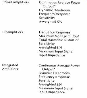
*-The continuous average power output rating includes the rated bandwidth, the rated load impedance, and the total harmonic distortion.
----------
Some manufacturers have been specifying the slew rate and rise time of their products. There are a variety of ways to make such measurements, and there is usually no assurance that the amplifier is behaving in a linear fashion as the measurement is being made. Furthermore, the data presented is interdependent with the amplifier's output rating in that a more powerful amplifier needs to slew faster than a less powerful amplifier in order to provide its full rated-output capability under dynamic conditions. After considering several possible methods of measurement, some of which appeared in intermediate drafts, the committee decided upon a new slew factor measurement which would yield the requisite information, under linear operating conditions, and be independent of the output rating of the device.
The slew factor is actually a measure of the highest frequency that can be applied at the input terminals of an amplifier and be reproduced at the output with no greater than 1 percent THD. That frequency, divided by 20 kHz, is defined as the slew factor. The input level is first adjusted to yield the rated output at a frequency of 1 kHz and is maintained at that level throughout the test.
An amplifier that incorporates an input low-pass filter to prevent TIM will have a very high slew factor, since the high frequency THD may never exceed 1 percent. The effect of such a filter would have been indicated in the frequency response rating, and, properly, it should not appear in the slew factor rating as well. If the slew rate or rise time had been measured directly, the effect of such a filter would be to degrade the rating even though the filter was designed into the amplifier specifically to avoid TIM problems. Many observers correlate a low slew rate, or a slow rise time, with high TIM. But, this is not necessarily the case. It depends upon what is causing the lower slew rate or the slower rise time-a low-pass filter designed to avoid TIM or a basic limitation in high-frequency power capability. The difficulty of interpreting a slew-rate or rise-time spec was precisely what the committee intended to avoid in establishing the slew factor rating.
TABLE II--SECONDARY DISCLOSURES.
Clipping Headroom
Output Impedance
Wideband Damping Factor
Low-Frequency Damping Factor
CCIR/ARM Signal-to-Noise Ratio
Tone-Control Response
Filter Cutoff Frequency
Filter Slope
Crosstalk
A-weighted Crosstalk
CCIR/ARM Crosstalk
SMPTE Intermodulation Distortion
IHF Intermodulation Distortion
Transient-Overload Recovery Time
Slew Factor
Reactive Load
Capacitive Load
Separation
Difference of Frequency Response
Gain -Tracking Error
Tone-Control Tracking Error
Real-Life Loads
Power amplifiers are customarily measured with a purely resistive load, and the FTC ruling is based upon such measurements. Yet, typical loudspeakers present a partially reactive load to the amplifier. Since the current through a reactive load is not in phase with the voltage across it, the operating conditions experienced by the amplifier's output circuitry are quite different in real life from what they are on the test bench. With a real loudspeaker, the amplifier's output-protective circuitry may be triggered at a substantially lower power level than it would be with a resistive load. In such a case, the "practical" power-output capability is less than that given by the standard ratings.
The reactive-load rating indicates the relative power capability of the amplifier when driving a dynamic loudspeaker compared to the amp's capability when driving a resistive load. Most protective-circuitry problems crop up only in the low-frequency region about the speaker's primary resonance. The standard specifies a load that simulates the impedance of a loudspeaker in that region. This reactive load was synthesized to represent the average impedance characteristics of some 20 commercial loudspeakers. It has a resonant frequency of about 50 Hz, an impedance at resonance of approximately 24 ohms and worst-case phase angles of ±39 degrees at 40 Hz and 63 Hz.
The maximum output-voltage capability of the amplifier (determined by the 1 percent THD point) is measured at 40 Hz and 63 Hz. The maximum output "power" is computed from the lesser of the two voltages, and the ratio of that "power" to the rated power, in decibels, is the reactive-load rating.
A reactive-load rating of 0 dB means that the amplifier is capable of supplying its advertised "power" into a typical loudspeaker. A negative reactive-load rating indicates that the level available to a typical dynamic loudspeaker is less than the advertised figure by that number of decibels.
The capacitive-load rating is given in terms of the range of values of capacitance that can be connected to the output terminals, in parallel with the rated output-load impedance, without evidence of instability or any change of ratings in excess of 10 percent.
Multi-Channel Amplifiers
Section 4 of the standard deals with multi-channel, i.e. stereo or quadraphonic, amplifiers. Essentially, it states that a multi-channel amplifier is rated in the same manner as is a single-channel amplifier, except that all channels are to be driven simultaneously when the measurements are made.
It also specifies a separation rating as the minimum value of channel separation, i.e. left-to-right signal leakage (in dB) at any frequency between 100 Hz and 10 kHz. Crosstalk between various inputs of the same channel, e.g. between the phono and tape inputs, etc., is measured and specified in a similar manner on a single-channel basis as outlined in section 3. A weighted-crosstalk measurement is also provided. It uses band-limited pink noise as the signal source, and the same weighting curve as is used for noise measurement. Note the difference between channel separation and crosstalk between inputs of the same channel.
Also included in the multi-channel-amplifier section are measurements of the difference in the frequency response of the various channels, the gain-tracking error, i.e. unbalance in the relative gain of the various channels as the volume control is changed, and a tone-control tracking error rating that accomplishes the same purpose for these controls.
Primary and Secondary Ratings
IHF-A-202 details the method of measurement for many different ratings. All are not equally important nor do all apply to a specific type of amplifier. Some of them are preamplifier measurements. Some are power amplifier measurements.
Some pertain to both. A list of the primary ratings, those that must be specified in order to claim an "IHF Specification," are listed in Table I for the three main categories of amplifiers.
(The standard, by the way, applies equally to the amplifier section of a receiver, tuner/preamp, or self-powered loudspeaker.) All of the other ratings are part of the secondary disclosures listed in Table II. Many of these, we hope, will also be used by the industry.
Acknowledgments
The effort to produce the new standard was a long and arduous one. The task could not have been accomplished without the active efforts of the many committee members and without the support of the IHF. I'd like to take this opportunity to thank them on my own behalf for their diligence and unswerving dedication to the task. And I suspect that they would like to join me in the hope that the document that was produced will faithfully serve its purpose now and will serve to encourage future research and advancement in this industry.
IHF-A-202 is available from the Institute of High Fidelity, 489 Fifth Avenue, New York, NY 10017 for $7.50.
(Source: Audio magazine, June 1978)
= = = =