
Manufacturer's Specifications:
Power Output: 36 watts per channel into 8 ohms.
Load Impedance: 4 or 8 ohms.
THD at 1 kHz: Less than 0.1% at 1 watt out; less than 1% at full rated power.
Frequency Response: 20 Hz to 20 kHz, ± 1 dB or less at full rated power.
S/N Ratio: 100 dB, IHF A-weighted, with inputs shorted.
Input Sensitivity: 1 V. Input Impedance: 100 kilohms.
Power Consumption: Approximately 250 watts.
Supply Voltage: U.S. version, 117 V; European version, 220 to 240 V. Output Tubes: Two 6CA7/EL34 tubes per channel.
Dimensions: 14 1/2 in. W x 11 1/2 in. H x 9 1/16 in. D (368 mm x 293 mm x 231 mm).
Weight: 481/2 lbs. (22 kg).
Price: $3,450.
Company Address: Edge Marketing, 611 B Santa Clara Ave., Venice, Cal. 90291.
----- --------
Would you believe this? A tube power amplifier imported from Japan! While not unprecedented, it is rare. I am surprised that more Japanese tube amplifiers are not imported, as many Japanese audiophiles are really into tube gear and quite a lot of it is available in Japan. I remember with fondness the mono tube amps that Luxman imported a number of years ago. I ran into the Air Tight products (including the larger ATM-2 stereo tube amplifier and the ATC-1 tube preamp) at the 1990 Winter Consumer Electronics Show and was intrigued. They had superb construction quality with very generously sized output transformers, and the sound in the demo room was rather good.
The company that makes the Air Tight products was formed by Mr. A. Miura, who worked with Lux for 30 years and served as president of Lux Audio of America between 1976 and 1979. In 1985, he resigned from Lux and, with two other partners, formed A & M Ltd. to pursue his dream of making premium vacuum-tube audio electronics.
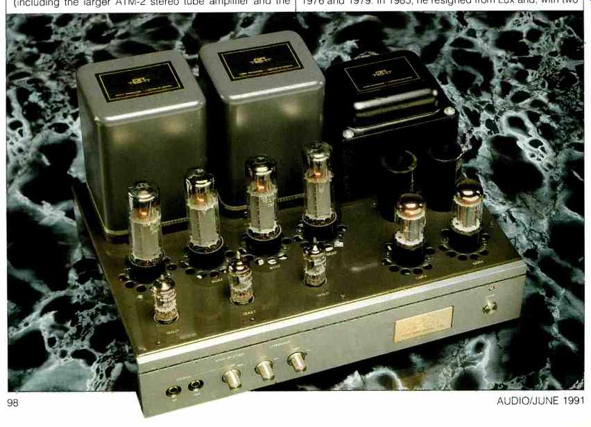
The ATM-1 is a stereo tube power amplifier built on one chassis, and it is rated at 36 watts per channel. Some of its features include the use of oxygen-free copper wire in its hand-wired construction, two rectifier tubes instead of solid state diodes, generous-sized Tamura output transformers, a copper-plated chassis, select tubes from name-brand manufacturers, and two sets of switchable signal inputs.
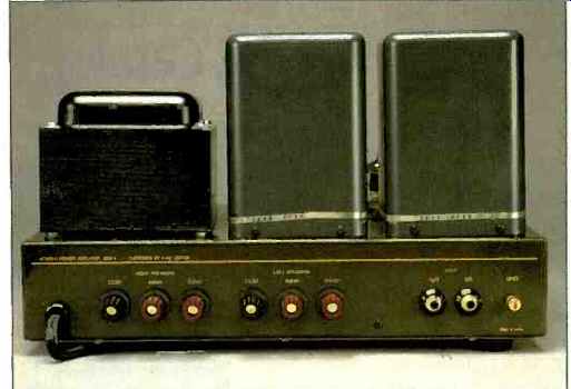
Front-panel attributes, from left to right, include two signal input phono jacks, a rotary selector switch, two rotary input level controls, the gold-colored brand and model plate, and a pushbutton power switch with a pilot light above it. On the rear panel are the a.c. power cord, three speaker output binding posts per channel, two additional signal input pho no jacks, and a ground post. An a.c. line fuse is inside the chassis. Being built in the old, traditional tube-amp way, the ATM-1 has all its tube sockets and transformers fastened to the top surface of the chassis. A series of large holes around the output- and rectifier-tube sockets insures a generous flow of cooling air for these tubes. The main filter capacitors appear to be mounted to the top of the chassis too, but are actually mounted with capacitor clamps underneath the top surface. Looking underneath the chassis reveals a beauty of construction rarely seen in a modern tube amplifier. The input and phase-inverter tube sockets are mounted on a copper plate held below the main chassis by 1/8-inch standoffs. A series of insulated terminals on stand offs, and the tube socket pins, serve as tie points for the circuit wiring. A number of ancillary components, such as bias-adjusting pots and the main high-voltage filter choke, are mounted underneath in the wiring area. About the only concession to modern practice here is the use of plastic tie wraps instead of the old lacing cord! Parts and construction quality appear to be first-rate in this unit.
The amplifier's construction couldn't be much simpler. A piece of steel is bent up to form the top, sides, front sub panel, and rear panel, with the bottom being open. A separate copper-plated bottom piece and a handsome front panel complete the picture. The bottom piece is slotted to allow air flow up through the interior space and out the holes around the output and rectifier tubes.
Circuit Description
Circuitry of the ATM-1 is quite conventional and topologically similar to a Marantz 8B, a classic old amp long out of production. From the switch that selects the front or rear input jack, the signal passes into a 100-kilohm input level control. Variable output from this control passes through an input coupling capacitor and a series resistor to the input tube's control grid. A 12AX7 dual triode is used for the left and right input stages, which are configured as ordinary common-cathode amplifier stages. The plate outputs of this first tube are direct-coupled into the grid of one of two tubes acting as long-tailed-pair phase inverters. A separate 12AU7 dual triode is used for this phase-inverter function in each channel. This kind of a phase inverter is, in reality, a differential amplifier with one input dynamically grounded through a capacitor and the other input driven with the signal from the first stage. The plate outputs of the phase-inverter stage are capacitor-coupled to the output tubes' control grids. Operation of the output stage is ultralinear, with fixed bias. A potentiometer in each output-stage grid circuit balances the plate current between the two output tubes. A bias level potentiometer in the power supply sets the overall bias voltage for both channels. Overall negative feedback, taken from the 16-ohm tap, is applied to the cathode of the first stage; this results in an overall noninverting input/output phase relationship.
High voltage from the power transformer secondary winding is full-wave rectified with the two 5AR4/GZ34 rectifier tubes, whose elements are wired in parallel, effectively forming two higher current diodes. Filtering is of the capacitor input type, with an input capacitance of 47 µF. A series filter choke of some 1.25-H inductance feeds into a final filter capacitance of about 150 µF to form the B+ supply to the output stages. This supply is resistor-capacitor decoupled to the driver or phase-inverter stage, and that supply point is, in turn, further decoupled as the supply to the first stage. A tap on the high-voltage secondary is half-wave rectified with a solid-state rectifier and RC-filtered to form the output-stage bias supply. All tubes in this design are run on a.c. from suitable secondary windings on the power transformer, which is typical practice in tube power amplifiers.
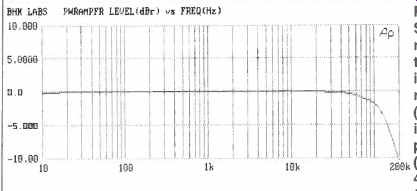
Fig. 1-Frequency response for 8-ohm loads on the 8-ohm taps.
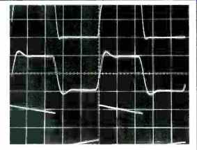
Fig. 2-Square-wave response at 8-ohm tap for 10 kHz into 8-ohm resistive
load (top), 10 kHz into 8 ohms paralleled by 2µF 0k(middle), and 40 Hz into
8 ohms (bottom). Scales: Vertical, 5 V/div.; horizontal, 20 µS/div. for 10-kHz
traces, 5 mS/div. for 40-Hz trace.
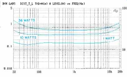
Fig. 3-THD + N (solid curves) and power output (dashed curves) vs. frequency,
with 8-ohm loads on the 8-ohm taps.
Read distortion from left-hand scale, power output from scales at right.

Fig. 4--SMPTE IM and 1-kHz THD + N vs. power output for 8-ohm load on 8-ohm
tap.
Measurements
Voltage gain and IHF sensitivity were measured first. With 8-ohm loading on the 8-ohm taps, voltage gain for the two channels measured 30.1 and 30.3 dB for left and right channels, respectively. Corresponding IHF input sensitivities were 88.9 and 87.0 mV.
Frequency response at 1 watt output was very similar for both channels. Figure 1 shows the 1-watt frequency response for 8-ohm loading on the 8-ohm tap for one of the channels. Notable here is the wide bandwidth and the lack of any peaking in the response up to the upper frequency limit of my Audio Precision measurement set. Related to the frequency response is the response to square waves. My usual set of these is shown in Fig. 2. The top trace is for 10 kHz with 8-ohm resistive loading. Damping, or amount of overshoot, is quite good for a tube amplifier. The waveforms for open-circuit loading and for 4-ohm loading on the 8-ohm tap look substantially like the top trace in the figure. This uniformity of response shape with loading speaks well for the high-frequency stability margin of this design. The middle trace shows the effect of adding a 2-µF capacitor across the 8-ohm load resistor. The amount of ringing with this load is well controlled. Finally, in the bottom trace, response to a 40-Hz square wave is shown; there is somewhat more tilt than I've seen in some of the other tube amplifiers that I have reviewed. Judging from the high-frequency and square-wave response, it appears that the output transformers used in the ATM-1 power amp are of high quality.
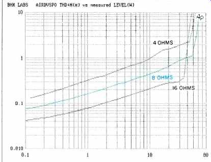
Fig. 5-THD + N vs. power for various loads on 8-ohm tap.
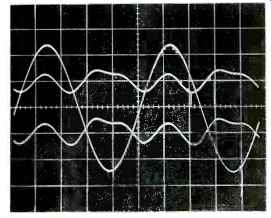
Fig. 6-Output and distortion residue for 1 kHz at 10 watts out into 8 ohms.
Right channel (upper residue trace) had 0.38% THD, left channel (bottom residue
trace) had 0.41%.
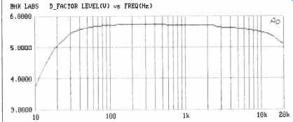
Fig. 7-Damping factor vs. frequency at 1 watt into 8 ohms.

Table I. Output noise, with inputs terminated by 1 kilohm. The IHF S/N ratios
were 87.7 dB for the left channel and 86.7 dB for the right.
Total harmonic distortion plus noise is shown in Fig. 3 for the left channel (which has slightly higher distortion than the right) as a function of frequency for three power levels.
Distortion doesn't rise much with increasing frequency; I consider this a desirable amplifier characteristic. Both 1kHz THD + N and SMPTE-IM distortion as functions of output power appear in Fig. 4. The load is constant at 8 ohms on the 8-ohm tap for this figure and for Fig. 3. What is interesting about this data is that the ratio of IM to THD is just about the "classic" 4:1 ratio for simple distortion character over most of the power range shown in the figure. I measured 1-kHz THD + N versus power output for 4-ohm loading on the 4-ohm tap as well; the 4-ohm and 8-ohm curves virtually overlaid, so performance into their respective loads is substantially the same for both taps. I cannot say this for some other tube amplifiers I have measured in the past. Figure 5 shows THD + N for different loads on the 8-ohm tap. As might be expected, distortion is the highest for the lowest load impedance. Even with a 16-ohm load, the amp puts out a good 30 watts or more per channel. This is a very well-behaved amplifier in all the measurements so far and, from the foregoing, should be very tolerant of tough speaker loads.
Figure 6 shows harmonic distortion residue for a 1-kHz signal at 10 watts out, as an oscilloscope trace of amplitude versus time. To a trained eye, these pictures give a good indication of the dominant harmonic content. In this case, the waveforms look like a mixture of second, third, and fourth harmonics, and not much else. To check further, I ran a spectrum analysis on the Audio Precision (not shown), which revealed harmonics of higher order at lower amplitude. The presence of a whole series of higher order harmonics, even in small amounts, may be significant in terms of how sweet or irritating an amplifier may sound. In future reports, I'll be able to include spectrum analyses showing these harmonics in detail.
I came up with a way, using the Audio Precision measurement system, to assess output impedance as a function of frequency and get the machine to compute, scale, and plot the damping factor itself. Such a plot for the ATM-1 is shown in Fig. 7. Results are fairly typical for tube power amplifiers.
Damping factor is quite uniform over most of the audio range and falls off at the frequency extremes. Output noise and IHF S/N are presented in Table I; the noise level is satisfactorily low.
Regarding clipping and dynamic headroom, the ATM-1 put out a steady-state 59 watts per channel at the visual onset of clipping, for a clipping headroom of 1.3 dB. With the IHF tone-burst signal, a power level of 58 watts per channel was observed. This translates to a dynamic headroom of 2.1 dB. The conservative power rating of this amp means that will play louder than one might expect.
Some miscellaneous measurements: The a.c. line draw at idle was 1.62 amperes and was 3.1 amps at rated power.
Plate supply voltage at idle was 480 V, dropping to 450 V at rated power. This is pretty good supply regulation.
Use and Listening Tests
Signal sources used to evaluate the ATM-1 included an Oracle turntable fitted with a Well Tempered Arm and Spectral MCR-1 Select cartridge, a Magnavox CDB-560 CD player feeding into a Wadia 2000 decoding computer, a Nakamichi 250 cassette recorder, and a Technics 1500 open-reel recorder. A Vendetta Research SCP-2B pre-preamp was used for playing records. The outputs from the Vendetta and the other high-level sources were selected and volume controlled with my reference selector switch and switched attenuator unit. Other power amps on hand were a Berning EA-2101, my own EAR 519s, a set of Cary Audio monoblock CAD-50SLs, and a pair of Carver Silver Sevens.
Speakers used were the Siefert Research Magnum III, Martin-Logan Monolith III, and Spica Angelus.
I was using the Siefert Research speakers when I first received the ATM-1. With these speakers, I found the sound of the ATM-1 to have amazing resolution and space but at the expense of some brightness and irritation on some program material. After doing some testing of the Cary Audio CAD-5OSLs, found myself continuing to use the Cary amps with the Martin-Logans for some weeks because I really like the sound from that combination. After measuring the ATM-1, I put it in this setup, driving the midrange panels of the Monoliths, and continued to use the Cary as a bass amp. With the ATM-1, the sound became a bit brighter, with increased resolution and detail. Again, as with the Sieferts earlier, the increased resolution was accompanied by some irritation on some material. Other material sounded very, very good.
I then took down the Monoliths and set up the Spica Angelus speakers to get a better idea of the sound of the ATM-1 used full range to drive these very good speakers.
This pair of Angelus speakers is not fully broken in yet and has a tendency to be a bit bright with most amplifiers. The ATM-1 drove these speakers nicely. The low end was slightly lean compared to my reference EAR 519s, although bass definition was excellent. Space, dimension, and resolution were very good. As with the other speakers used, there was some edginess and irritation on some program material.
This effect was more noticeable with CD sources than with records. One person that I loaned the ATM-1 to had nothing but good things to say about its sound.
I think the ATM-1 is a beautifully made little amp that delivers a high degree of resolution, space, and detail. Its sound should appeal to those with these sonic priorities.
--Bascom H. King
(Source: Audio magazine, June 1991)
= = = =