
By: Kenneth L. Kantor [Kenneth L. Kantor is the president of Product Design and Evaluation Services, a consumer electronics consulting company located in San Francisco, Calif.]
Loudspeakers, like other sex symbols, have at certain times been considered most desirable when fleshy and substantial, and, at other times, when lithe and ethereal. Macho woofers had their days of glory, but flat panel speakers have remained the cat's meow since before most of us were born. I confess to getting a little bit lightheaded when listening to really good panel speakers. They look so in capable of filling a room the way they do, it's easy to forget they're around.
However, there is much more to the sound of the best flat speakers than the power of suggestion. Although a technologically diverse bunch, flat speakers share some important general characteristics that set them apart from more conventional box types.
Properly applied, these characteristics can lend themselves to some of the best sound many of us have had the pleasure of hearing.
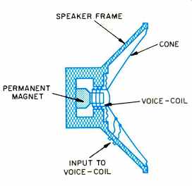
Fig. 1-Cross-section of a typical electrodynamic cone driver. (After Edgar
Villchur.)

Fig. 2-Polar radiation patterns, at three frequencies, for a piston speaker
in a small cabinet. (After Leo Beranek.)
--- Flat-fronted electrodynamic driver from Phase Technology.
The Scoop on the Cone
The epitome of conventional loud speaker design is the ubiquitous electrodynamic cone driver, a cross-section of which is shown in Fig. 1. Alternating electric current from a power amplifier flows through the driver's voice -coil, generating a magnetic field that interacts with the field of the permanent magnet, causing the coil to vibrate forward and back. The coil, in turn, is attached to a diaphragm in order to more efficiently couple its motion to the air. This diaphragm is formed in the shape of a cone to in crease its ability to move as a rigid unit in response to voice-coil forces. This kind of uniform in -and -out cone movement is referred to as "pistonic motion," for obvious reasons. Electrodynamic cone speakers made their first strong appearance in radios of the 1930s, and rapidly came to outnumber competitive electrostatic units due to their reliability and relative ease of manufacture.
While widely accepted, the cone driver has several drawbacks. First is the matter of mass. A conical diaphragm is simply heavier than a flat radiator of similar composition and area. Any excess driver mass tends to impair efficiency, high -frequency response, and transient behavior. If other factors can be kept equal, the lower the mass of a radiator compared to the air it moves, the better. At the same time, response irregularities and distortion are introduced because, cone or not, it is impossible to achieve perfectly rigid motion when all driving forces are applied over a small portion of the diaphragm. Some flexing is inevitable, and this leads to deviation from ideal driver behavior; most notable are harmonic distortion and radiation-pattern irregularities. The concave shape of the radiator also has a negative effect on frequency response and radiation pattern, since different points on the surface create wavefronts with varying phase. However, this is a minor problem unless unusually deep cones are used to radiate a range of frequencies that is much wider than normal.
Pistonic motion produces very even wavefronts at frequencies where the wavelength is long compared to the cone diameter, but at higher frequencies cones begin to radiate with increasingly uneven polar patterns. Figure 2 shows approximate radiation pat terns for a piston vibrating at three different frequencies in a small cabinet.
The pattern gets more directional as the ratio of the wavelength to the diaphragm diameter decreases. At the highest frequency, the effects often called "beaming" and "lobing" can be seen.
Beaming, lobing, flexing, and mass are the undoing of the cone. Combined, they make it impossible to de sign a single -cone unit to cover the entire audible spectrum. Hence the need for multiple drivers and crossover networks, with their attendant response problems.
It's certainly true that cones can make good speakers, especially when given some help at the high end--by an electrodynamic dome radiator, for example. Cones really excel at low frequencies, where their mass and shape are not serious drawbacks. Electrodynamic loudspeakers also have significant advantages in power handling and can therefore provide very high sound levels at a reasonable cost. Numerous advances in materials and de sign technology have aided in the creation of really extraordinary electrodynamic cone loudspeakers, so I don't want to sell them short. Still, the fact remains that constant battles with crossover networks, response irregularities, and distortion have led many designers to consider various "flat" speaker technologies as advantageous alternatives. Or maybe it's just the sex appeal.
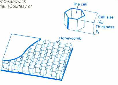
Fig. 3-Honeycomb-sandwich diaphragm material. (Courtesy of Mitsubishi.)
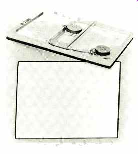
---- The B.E.S. speaker. The voice-coil-and-magnet assembly on the bridge
drives the large, flat polymer woofer diaphragm; the voice -coil and magnet
in the near corner drive a smaller diaphragm section for reproducing mid
-frequencies.
Electrodynamic Variations
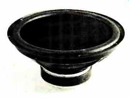
One thing loudspeaker engineers tried doing to improve the electrodynamic cone driver was to fill it with material to form a solid unit with a flat, front-radiating surface. KEF originally introduced its venerable B139 woofer in 1962, and it's still in use today. This oval -shaped unit is constructed out of polystyrene and thin metal foil. In addition to providing a flat radiating surface, the solid -cone approach allows very little diaphragm flexure and is effective at preventing internal cabinet reflections from exiting through the driver and coloring the sound. When compared to a conventional unit of similar dimensions, the B139 exhibits somewhat higher moving mass. This means that the driver is best suited to systems which have three (or more) drivers and to subwoofers, since in both cases a lower cutoff frequency is acceptable. An American company, Phase Technology, has more recently introduced new approaches to manufacturing and materials technology.
The result is a line of loudspeakers based on solid-cone drivers with diameters of 5 1/4, 6, 8, and 10 inches.
Another interesting variation on the electrodynamic driver uses a cone that is simply flattened back into a plane, with the required stiffness achieved through some other means, such as high-tech diaphragm materials, in stead of the cone shape. The ultimate goal is to provide a nice, rigid radiating surface for low -distortion operation while also eliminating the cavity for smooth frequency response and a predictable radiation pattern. This "planar electrodynamic" approach is currently popular with several Japanese designers. Notable are the Mitsubishi, Technics, and Pioneer honeycomb drivers, among others. Usually the materials employed are laminates, with complex geometric structures composed of several layers. Mitsubishi's material is illustrated in Fig. 3. Sony has even gone so far as to combine the use of laminates with multiple voice-coils distributed around the diaphragm in an attempt to reduce flexing.
Losing weight, however. is not so easy, as everyone knows. By the time a practical planar electrodynamic driver is produced, what with the layers and the glues and this and that, it can be discouraging to put it on the scale.
True, the cavity is gone; looks nice, can't hurt. Mass? Still a lot left. Flexing? Still hard to conquer, and the fundamental mode of operation remains pistonic. The best of the planar electrodynamics do show improved frequency response and lower distortion, but too often, the technology is used principally for marketing or cosmetic reasons.
An interesting relative of the flat diaphragm is sometimes called the electrodynamic panel speaker. These appeared as the first "picture frame" loudspeakers, predating Japanese honeycomb models by 10 years or so.
Many seasoned audio hobbyists may remember the Poly-Planar series of products, made from Styrofoam by ERA Acoustics. According to Donald Grieg, who was heavily involved in the development of the Poly-Planars, the idea originated from a violin-playing engineer's desire to duplicate that instrument's mode of sound radiation.
While successful in a wide range of applications, such as outdoor use, the Poly-Planar approach never really conquered audiophile territory.
The electrodynamic panel speaker puts less emphasis on eliminating diaphragm flexing, instead attempting to control and utilize it. In this approach, advanced in the line of panel speakers from B.E.S., vibrational modes are tailored to create a kind of diaphragm pulsation wherein the two sides of the radiator move in opposite directions, resulting in monopolar wavefronts. This helps to allow a relatively omnidirectional radiation pattern to be obtained without the use of an acoustical enclosure or baffle.
About Dipoles
Before we get any flatter, there is something important to discuss: Dipoles. The drivers discussed so far are most often used as monopoles. With pistons, this means that sound waves are radiated into the listening room from only one surface of the moving diaphragm. The waves that leave the opposite side of the diaphragm are either absorbed inside the speaker or are substantially altered in their amplitude and phase to supplement the front radiation, as in the bass reflex enclosure. With the B.E.S. speaker, front and rear surfaces pulse outward in unison. In either case, at any given instant the monopole loudspeaker is either "pushing" or "pulling"; it is either pressurizing or rarefying the air that surrounds it.
Fig. 4 Polar radiation patterns, at three frequencies, for a dipole speaker. (After Beranek.)
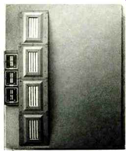
--- A portion of Infinity's Reference Standard 4.5 system, showing the
planar magnetic EMIT tweeters and EMIM midrange drivers. The EMITs are monopoles,
the EMIMs dipoles.
The speaker technologies we will examine next are best suited to dipolar (also correctly called "bipolar" or "doublet") operation, especially when used full -range. In a dipole, sound waves are allowed to leave both sides of the moving diaphragm simultaneously. At every instant, the loud speaker is pressurizing the air on one side of the diaphragm while rarefying it on the other side. The speaker radiates front and rear waves exactly out of phase. Directly to the sides of the diaphragm, these waves cancel and no energy remains. This results in the type of radiation patterns depicted in Fig. 4.
Dipole behavior is very much affected by operating environment. At the very lowest frequencies, the dipole can arguably be said to reduce the effect of room resonances. Unfortunately, small changes in room characteristics and speaker placement have a large effect on both frequency response and polar pattern. In an anechoic, free-field environment, the rear wave of the speaker disappears into the sunset; it does not in any way bother the on-axis response. In a real room, however, the rear wave will eventually catch up to the front wave, and cancellation will result. This is usually manifested as a weak bass response, especially on sustained notes such as cello or pipe organ. Sounds of a more transient nature-that of a kettledrum, for example--are reproduced more fully, due to the finite delay that occurs before the rear wave returns. This results in many panel speakers having a schizophrenic bass response, at times seeming deep and full, at other times rather thin.
At midrange and treble frequencies, the reflected rear wave can be more of an advantage. Cancellation is still present, but at shorter wavelengths the rear and front waves tend to add in randomized phase, resulting in less average spectral error. The delayed rear wave can contribute a very appealing sense of depth and spaciousness to the sound, like a built-in ambience processor. This effect is, naturally, adjustable only through speaker placement, but it usually does work well.
By comparing the various polar pat terns typical of the dipole (Fig. 4) with those of the monopole piston (Fig. 2), another important dipole characteristic can be seen: While the directivity of a dipole also increases with frequency, its polar pattern always remains sym metrical, front to rear. Unlike the mono-pole, the dipole never radiates energy directly to its sides, at any frequency.
This helps to reduce unwanted early room reflections, to the advantage of both imaging and tonal accuracy. Although monopoles are naturally directional at high frequencies, they can never be so at low frequencies.
All in all, it is not possible to categorically state that either the monopole or the dipole makes a universally superior reproducer. Opinions vary, but theoretically the monopole can be said to al low a more accurate re-creation of an electrical input signal, owing to the absence. of the antiphase rear wave. At its best it provides a more predictable low-frequency response and is less subject to room and placement variations. Nevertheless, dipoles sometimes sound subjectively superior. Divorced from the particular technology used, be it planar or box, electrostatic or electromagnetic, the dipole's real ad vantages are its ability to provide a very convincing illusion of depth and space and its reduction of side -wall reflections.
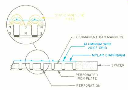
Fig. 5 Cross-section of a Magnepan planar magnetic loudspeaker.
Planar Magnetics
The drivers we have looked at thus far are not the only ways to put electro magnetic energy to work making sound. Rather than concentrating a long electrical conductor in a small voice -coil, the planar magnetic speaker distributes its long conductor over a large, lightweight diaphragm. (Strictly speaking, the planar magnetic is still an electrodynamic speaker, but it is dissimilar enough from the typical one to warrant a name of its own.) The reason a very lightweight diaphragm can be used is that, by spreading out the conductor path, the generated force is distributed uniformly over the entire radiating surface. There is very little tendency for the diaphragm to flex, even if it is very large. This kind of force distribution is a key element in all wide-range planar loudspeakers.
An important consequence of distributed-force operation is that it gives the designer a great deal of flexibility in choosing the shape of the diaphragm.
Some kind of retaining force is required to keep the diaphragm properly located when at rest, but there is no need for the kind of critical mechanism used to keep a voice-coil correctly positioned. This freedom to choose a shape helps the designer tailor the radiation pattern to some extent, including independent adjustment of horizontal and vertical directivity. For ex ample, a tall, narrow radiator produces wavefronts that can reduce floor and ceiling reflections while maintaining good horizontal dispersion. It still re mains extremely difficult to control directivity well enough to allow a planar magnetic loudspeaker to use one single, full-range driver, so multiple drivers are generally used.
Of course, new distortion mechanisms enter the picture in place of diaphragm flexing. One tricky problem encountered when designing a planar magnetic is how to make the magnetic field. This field must be strong and uniform over the surface of the speaker, it must be even enough so that no changes in force occur as the diaphragm moves in and out, and the actual magnet structure must not un duly disturb the radiation of the front and rear waves. This usually requires many small magnets on some kind of perforated structure, as shown in Fig. 5. The electrical conductor is often implemented by binding wires to a thin plastic sheet; this method works well for lower range units. To reduce moving mass for higher frequency operation, a conductor pattern can be etched directly on a piece of metalized plastic. In this case, care must be taken to provide adequate current-handling capacity in the conductor.
How well the magnetic system works largely determines the dynamic range of the loudspeaker. Peak output is rarely limited by gradual heat buildup, as with a voice-coil driver, but rather by the diaphragm either leaving the linear magnetic field or actually hitting the magnet structure. Since this type of overload is essentially instantaneous and does not depend on the length of the input pulse, planar magnetics are not well suited to the very high transient sound levels which can be produced by regular dynamic speakers.
On the other hand, overload is not usually destructive to the speaker, and acceptably high average levels can readily be generated.
An extra benefit of the planar magnetic approach is that the input impedance of the driver looks more like a pure resistance than does that of a conventional dynamic driver. This results mostly from the absence of a highly inductive voice-coil and from the smaller quantity of stored kinetic energy that the large-area, low-mass surface provides. A resistive input impedance is easier for amplifiers and speaker cables to drive, and simplifies crossover design.
In total, planar magnetics provide low -mass operation for good frequency and transient performance without incurring excessive diaphragm distortion. They allow a good degree of pat tern control, eliminate the response effects associated with cone cavities, and can provide dipole radiation across the audio spectrum. Over the past decade or so, planar magnetics have been refined by a few dedicated companies and individuals. The technology has been applied with excellent results both in wide -range dipoles (such as Magnepan's Magneplanar loudspeakers) and in upper frequency drivers (such as Infinity's EMIT and EMIM drivers, which are monopolar and dipolar, respectively).
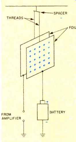
Fig. 6-Construction of an ultra-simple electrostatic driver. (See text.)
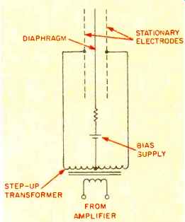
Fig. 7-Circuit of a modern electrostatic speaker. (After Arthur Janszen.)
Going for the Ribbon
The logical extension of the planar magnetic concept is the complete metamorphosis of the electrical conductor into the actual radiating surface. A normal round wire couldn't possibly move enough air to be useful, so the conductor is shaped into thin, ribbon-like strips. Ribbon technology was used in some of the first high-quality broadcast and recording microphones, but at the time was not efficient enough for successful loud speaker use. As magnetic-material technology improved over the years, it became possible to build ribbon tweeters with low, but passable, efficiency.
Only recently have engineers, helped out by stronger magnets and bigger amps, been able to create really good wide -range ribbon loudspeakers.
A traditional problem with ribbons has been that their impedance, while highly resistive, is quite low. The luxury of using as much conductor as is required to achieve a satisfactory input impedance is not available to the ribbon designer. Some low-cost ribbons use impedance-matching transformers, but high -current transformers are difficult to make and can add response errors and distortion. Therefore, they are avoided in more critical designs.
The very low impedance of ribbons used to mean instant amplifier trouble.
It still can, but the best of the new amps with high current capability handle ribbon speakers quite well.
Impedance and efficiency aside, ribbons share most of the technical ad vantages and limitations of planar magnetics, including the benefits of distributed-force drive. Again, the magnet design is critical to success, and radiator shape is flexible. Ribbons have a still lower moving mass and are well suited to tweeters-this despite units of seriously questionable value adorning some moderately priced loudspeakers. For those willing to pay the price, top-quality ribbons are often the tweeter of choice. A few multi-driver, full-range ribbon dipoles remain secluded at the high end of audio. They tend to be hard to drive, hard to place, and hard to afford, but the best models are worth the trouble.
Repulsion and Attraction
At last, we come to the beginning.
Electrostatic loudspeakers have been around for well over six decades, and it would be easy to fill several books detailing the theories, design variations, and patents related to them. The diverse electrodynamic transducers described above share a common principle of operation: They rely on the interaction of an electric current with a magnetic field to produce force. In contrast, electrostatic transducers, by definition, utilize the repulsion and at traction of like and unlike electrical charges as their fundamental basis of operation.
To best understand the workings of an electrostatic loudspeaker, we can build one from scratch-on paper, at least. The simplest electrostatic driver one could possibly construct is shown in Fig. 6. The electrodes might be made from very thin metal foil; they would, indeed, vibrate in response to an applied a.c. voltage. Varying positive and negative charges on the electrode connected to the power amp would repel or attract the positive charges on the electrode connected to the battery's positive terminal. In fact, the motional force would be well distributed over the radiating surface, so we could expect little flexing and good transient response. Unfortunately, both practical and theoretical limitations intrude. In examining these difficulties, many of the key approaches taken by successful modern designs become understandable.
The two main problems we would find immediately upon listening, or at least trying to listen, to the driver of Fig. 6 would concern sensitivity and distortion. Several thousand volts of signal would be required from our amplifier in order to hear any sound at alt. Very little current flows in the system, so the actual power consumption (voltage times current) would be low. But even without current, the kind of voltage required is orders of magnitude beyond the output capabilities of even the most powerful audio amps. The distortion problem comes from the uneven way that force is generated in the system. A rapid increase in force occurs as the electrodes get closer together; like wise, the force quickly decreases as the separation becomes greater. This is an unavoidable result of the proper ties of charged particles, and it leads to a very nonlinear relationship be tween input voltage and the motion of the electrodes.
Assuming we didn't care about distortion and went ahead and built a special high-voltage power amp for our rudimentary system, we would soon discover a third problem, destructive electrical sparks. As high input levels caused the electrodes to get too close to one another, or perhaps even touch, high-voltage discharges would occur.
These sparks might damage the electrodes or the power amp and would certainly be annoying to hear. So we must next find some insulating material that can stand very high voltages when used in thin layers. Since no current is supposed to flow across our electrodes, an insulator between them should not present any theoretical problem.
Rather than build a new type of power amp, a more convenient solution to the problem of drive voltage is to use a step-up transformer to feed the electrodes. The design of such a transformer is very difficult, but because the electrode current is very low, it is not impossible. So we can move on to tackle the distortion problem. The force error we encounter is the result of the physical laws governing the behavior of our system. Therefore, we must explore an alternative system to solve our problem. Cleverly borrowing from other people's work, we realize that if we could use some sort of push-pull arrangement, constant force could be achieved and distortion would be eliminated.
Figure 7 shows a method of combining the use of a transformer with a push-pull approach. The stepped-up audio is applied to acoustically transparent electrodes which attract and repel a central membrane biased to a high voltage with a separate power supply. The use of a high-value resistor to isolate the center electrode results in a form of operation known as "constant charge," referring to the fact that the number of electrons on the electrode remains essentially fixed as it moves.
Constant-charge operation became popular in the '50s. pioneered in En gland by Peter Walker, the inventor of the landmark Quad ESL, and in the U.S. by Arthur Janszen. Constant charge operation provides very low distortion and is now universally accepted by designers.
Another of Janszen's important contributions to the development of the modern electrostatic loudspeaker was the introduction of what he called "sheathed conductor" technology.
This was invented to address the issue of sparking, mentioned earlier. In Janszen's approach, now used by Acoustat, a grid of insulated wires comprises the fixed electrodes. This sounds like a trivial advance, but it is, in fact, very difficult to find insulation techniques that can withstand the voltages required and yet allow the complex system of fields and charges to operate correctly. There are many other ways to construct the fixed electrodes and prevent electrical arcing. Various conductor and insulator combinations have been or are now in use, including inert insulating gases filling the region between the various electrodes. In Walker's recent Quad ESL-63, an internal antenna rapidly detects electrical discharges, shutting off the drive voltage in response. This technique, combined with an input-limiting circuit, eliminates the need for insulated electrodes altogether.
Even with all the advances realized over the last few years, today's electrostatics are not the first choice for pro viding high -volume sound. It's true that they have finally shed their predecessors' propensity for catastrophic failure every time a stylus was dropped or a bass drum was hit too hard; in fact, modern units can be very reliable and are capable of high output. However, partly due to the transformers used, they are not efficient nor are they easy loads to drive. For a while, it seemed that manufacturers were making an effort to integrate high-voltage, transformerless amplifiers into electrostatic designs, but this trend seems to have waned, probably for a combination of technical and marketing reasons.
More than any of the designs discussed so far, electrostatic drivers are adaptable to full-range use (within the inherent low-frequency limitations of dipoles). By three-dimensional shaping of the diaphragm; by tall, narrow geometry, or by using a phased array of radiators, polar patterns can be optimized over a very wide range of frequencies. This is an important advantage over those planar approaches which are not so easily suited to these alterations. In the Quad ESL-63, an array of vertically oriented independent radiators are fed from a series of delay lines to maintain a very constant horizontal dipole figure-eight pattern over the audible spectrum. In this way, an essentially flat radiator can be made to combine many of the benefits of a point source with those of a dipole. In the ESL-63, multiple full-range drivers are used, so none of the usual cross over troubles appear.
Martin-Logan has refined a different approach to controlling directivity. By using a large, curved electrode-and-diaphragm assembly, their loudspeakers can produce a semi-cylindrical wavefront similar to that of a vertical line source. Although the shape is not inexpensive to manufacture, floor, ceiling, and wall reflections are reduced without sacrificing coverage. The curved shape is used in a single-driver, full-range speaker as well as one using an electrodynamic subwoofer.
Acoustat too produces full-range speakers that have a vertical line-source characteristic, using instead a tall and narrow flat electrode.
Electrostatic loudspeakers have long held captive a core of fanatical devotees. Even at a time when listening to electrostatics invariably meant clamping your head in the right position to hear the highs, settling for background-music sound levels and thin bass, and making frequent trips to the repair shop, there were those who would have nothing else. Electrostatics do have a sound of their own, even if only due to their dipolar operation and lack of crossover effects. And some thing about transparent, high-voltage speakers seems to hint at communication beyond the sensory norm.
Contrary to common belief, though, electrostatics--especially full-range ones--do not have extraordinarily extended top ends nor fast rise-times.
There are many high -quality dynamic tweeters that can easily outperform them in these areas. Transient response can be excellent from the point of view of damping and phase, but the truth is that the air-load mass on a large diaphragm requires a very large force to accelerate quickly. Since there is virtually no scientific evidence to support the audible need for response much above 20 kHz, this should not be considered a problem, just an interesting fact.
All things considered, there are many things that make sense about flat loudspeakers. As a group, they have really come into their own over the last decade or so, and I have every reason to believe they will continue to improve.
We might expect to eventually see a resurgence of interest in direct-drive, high-voltage amplification for electrostatics, and new magnetic materials applicable to ribbons and planar magnetics are appearing regularly.
At some point in the future, the use of cones as we know them will probably be confined to the bottom three or four octaves of the audible spectrum, where I think they do what they do best. And, of course, we'll still use them for ice cream.
(adapted from Audio magazine, Aug 1987)
= = = =