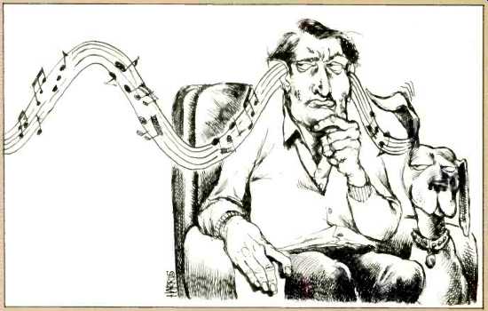
Polarity Convention
In keeping with the spirit of the audio Rosetta Stone [1], I propose that from this point forward the entire audio industry take a basic step which is capable of improving the quality of the listening experience from the present and future product without adding any cost to that product. I propose that the polarity convention of every part of the audio chain be identified and this information made available to establish the net polarity of the reproduced sound relative to the original performance. In those cases where the original performance does not arise as an acoustic sound field, such as computer or synthesized signals, and in which the performer or composer considers polarity to be artistically important, I suggest that the score or software include this information.
In natural sounds there is a definite physical relationship between sound pressure and the mechanical displacement of air molecules which gave rise to that pressure. There is also a definite physical relationship between the pressure wave impinging on a boundary and the resultant sound pressure wave reflected from that boundary, as well as the seismic or acoustic wave which continues past the boundary.
For several decades there has been evidence that the human perception of sound includes this relationship as a subtle cue. The subtlety of this effect has, until quite recently, been more than masked by other aberrations in the recording and reproduction of sound. But, with the constant improvement in audio systems, we have now reached the state where many persons can readily perceive the coloration caused by improper polarity in the reproduced sound. We must now recognize this and set our house in order.
Accountability of polarity should include, but not be limited to:
- Groove wall direction of displacement for positive sound pressure in crease at the microphone for all phonograph records, including those of the direct-to-disc type.
- FM transmitter direction of carrier deviation and of stereo multiplexing for positive sound pressure increase at the microphone for all live broadcasts, and for groove wall direction of displacement and magnetic tape flux change for reproduced program material.
- FM receiver demodulated polarity of output voltage for upward carrier deviation of the received signal and for de-multiplexed signals.
- Phonograph cartridge voltage polarity as related to direction of groove wall displacement.
- All electronic equipment polarity convention, whether inverting or non inverting between input and output, for all combinations of terminals and control switching which a user may utilize in normal operation.
- Polarity convention for individual microphones relating increase of sound pressure (or increase of particle velocity) to direction of voltage or cur rent for which the microphone is designed.
- Sound reproducer polarity of sound pressure at the listener's location relative to voltage or current applied at the reproducer terminals.
- In the great majority of cases, a record producer, particularly those producing direct-to-disc records, has maintained a de facto convention for their own product. Measuring this convention and supplying the information on the record jacket of new re leases can allow us to adjust the polarity of speaker leads for increased accuracy from those re cords which we now own from those companies, as well as the record so marked.
There is truly no aspect of the audio industry that lies apart from this first step into providing information relating to better sound. Sound reinforcement in the performing arts should be included, as well as in motion pictures and television. At this time I am asking for a book keeping tally which we can use to gain a small but important increase in the enjoyment of sound from the existing product. If portions of the audio industry enter into the spirit of this self analysis, I suspect that we will begin an inexorable move to improve the end product. I see no way in which this can hurt the industry, and there are many obvious benefits that can come from cleaning up our act. Eventually it must lead to industry standardization.
In those circumstances where it is not easy to quantify polarity or phase as a function of frequency, I suggest that recourse be made to a simple audio Rosetta Stone. A handclap can establish gross polarity through quite complicated networks. It can also re veal those all-too-frequent cases where a magnetic tape playback is out of phase with the line feed into the recorder. If such a signal, either electronically generated or produced by physical means, is included on a leader, tapes shared by various broadcast agencies, possibly subjected to indeterminate re-recordings, can be readily verified for polarity. While not normally intended for broadcast, such signals could be transmitted for listener verification and setup, much as Dolby tones are now transmitted prior to playback of encoded programs.
Aware of the distinct audibility of polarity, and, in my own experiments, the limited audibility of phase shifts other than zero or 180°, I have, since 1974, measured and provided a standard for the phase reference of loudspeaker reproduction, the so called absolute phase. Every loudspeaker which reviews in these pages has its absolute phase identified in the continuum of angles from in-phase through phase reversal as a function of frequency. I suggest that this voltage-to-listener position sound-pressure convention be adopted for polarity determination of loudspeaker reproduction, taking into account phase shift as a function of frequency, as we do in our Audio reviews.
Leaders in the audio field, such as Hansen and Madsen [2], have pointed out the audible difference caused by improper polarity, and recently Moncrieff [3] has taken the important step of alerting a segment of the listening public to this effect and has identified a number of amplifiers which invert signal polarity. I now publicly call upon the entire audio industry, from computer composer through loudspeaker and headphone manufacturer, to acknowledge polarity as a psychoacoustic parameter and identify either the polarity or phase convention of their product.
--Richard C. Heyser; Senior Editor, Audio Magazine
References
1. R.C. Heyser, "Acoustic Rosetta Stone," Audio, Jan., 1979, p. 66.
2. V. Hansen and E.R. Madsen, "On Aural Phase Detection," J. Audio En& Soc., Vol. 22, p. 10 (Part I) and p. 783 (Part II), Jan. & Dec., Nos. 1 & 10.
3. J.P. Moncrieff, "Phase Inversion," Int. Audio Review, No. 4 (1978).
Omitted Factors in Audio Design
I want to share with you some thoughts on and data affecting the current state of audio design, some of which appeared in the IEEE TIM Conference Proceedings, Tulsa, 1978.
Given the resources and talent in vested in audio design today, it seems to me that products should have emerged that would be entirely sonically acceptable until a radically new technology offers advantages currently impossible with present design techniques. The reason this has not happened is, I think, because designers have not yet considered all of the factors necessary to a successful design. I would like to discuss some of these factors and attempt to show what must be done in the future to more completely define the audio design process.
I have divided audio design factors into three major areas:
1. Standard specifications;
2. New distortion measurement methods, and
3. "X" factors, ones relating to the incompletely understood hearing pro cess or psychoacoustics.
Standard specifications have been with us for many years. They are found listed in typical sales brochures and are often the major criteria the con sumer uses to select the product. Some examples are frequency response, harmonic and IM distortion, maximum output power or voltage, damping factor, wow and flutter, .... Each of these is important, but often other factors are disregarded to make them as impressive as possible. Usually these specifications are so excellent that it is difficult to understand how further improvement could possibly be audible under any circumstance.
New distortion measurement methods have been developed in recent years to help the designer further optimize a design. Some of these measurements are:
1. TIM or SID (transient intermodulation distortion, slew induced distortion),
2. IIM (interface intermodulation distortion),
3. ED (envelope distortion),
4. Distortion related to the input impedance of the phono preamplifier, and
5. Resonance problems related to phono turntable, tonearm, and cartridge.
TIM or SID distortion is related to the slew rate of a particular amplifier circuit. It has been brought to the attention of audio designers through the research of Dr. Matti Otala of Finland, and the recent series in Audio by Jung, Stephens, and Todd focused on this type of distortion. It is essentially the measure of the ability of an amplifier to respond to a rapid change in amplitude of the input signal. A good many designers currently feel that a slew rate of 50 V/ p S in a 100-watt power amplifier and 5 V/uS in a phono preamp is necessary to pass all possible inputs without TIM or SID [1].
IIM, discussed for the first time only a year ago [2], is essentially related to the interaction between the amplifier and the loudspeaker. The theory states that under some circumstances, negative feedback can reduce the performance of an amplifier when driving a real loudspeaker as a load. This discussion also covers some of the virtues of the triode vacuum tube as opposed to the pentode in power amplifiers, as well as some of the problems with bass performance in some vacuum-tube circuits.
ED, recently discussed by two engineers from Sansui (3), is related to the interaction of the various stages of an amplifier (or sometimes between channels), which can be very significant with changing amplitude levels.
They developed a test signal which more closely simulates actual musical signals than do continuous tones for the testing of power amplifiers. The results confirm the knowledge of many designers that power supply regulation is quite important in a quality design.
Input-Impedance Distortion related to the phono input stage has been discussed recently by Yamaha (4), who say that this is essentially undetected by conventional test measurements.
Essentially, they say that we must test a circuit with realistic input impedances, which can be greater than 10,000 ohms, to give a realistic assessment of the distortion contribution of the input stage.
Phono System Resonances and related problems are now receiving more attention in various circles. While not directly related to electronic design, this is nonetheless an important area where work can be done to improve high-fidelity reproduction. Much thought is going into the new cartridge designs, particularly in the cantilevers, into tonearms and their mountings, into bases and suspensions, and into platter mats. This last was the subject of articles by Stockton in the June, 1979, issue of Audio and by Jean Hiraga in the April, 1978, issue of the British publication Hi-Fi News and Record Review. An understanding of these distortions, even though measurement techniques have not yet been standardized, gives designers significantly greater insight into the de sign of circuitry which will be successful. However, one further area remains, one which is important to a successful design and involves factors yet to be measured in any comprehensive manner or understood fully. This area is the subjective response of an experienced individual to a design, and I call this "X" factor. Efforts to bring these "X" factors into a coherent scheme are being made by Richard Heyser [6] and by Michael Gerzon [7] of Oxford University, as well as several others, who are attempting to more accurately characterize the listening process in mathematical terms. Just how these things relate to major measurement areas 1 and 2 is not clear, but it is important that a designer take all three areas into consideration, as a lack of attention to any one of them can make an otherwise good design less than successful in the final analysis.
------------------

Fig. 1--TIM (30,30) spectrum superimposed on the spectrum of a cymbal crash from the GAS moving-coil cartridge playing The Perfect Song, Sheffield Vol. 3, Lab 1.

Fig. 2--The spectrum of a Shure M91ED moving-magnet cartridge playing
a cymbal crash; same source as in Fig. 1.
Fig. 3--The rise time of the Shure M91ED playing a 1kHz square wave from the CBS STR-112 test record.
Fig. 4--The spectrum of the Denon 1035 moving-coil cartridge playing the same cymbal crash as in Fig. 1.
Fig. 5--The GAS cartridge with conical stylus, playing the same cymbal crash as in Fig. 1.
Fig. 6--Rise time of the Ortofon MC20 moving-coil cartridge playing the 1-kHz square wave on the CBS STR-112 test record.
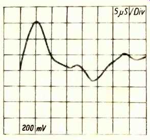
Fig. 7--The rise time of the Ortofon MC20 mistracking a 1 kHz sine wave
on the B&K 2010 test record
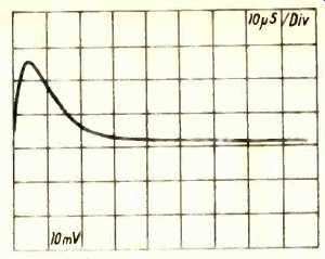
Fig. 8--The TIM (30,30) waveform, without
15 kHz. This is composed of a 3.18-kHz square wave and a 15-kHz sine
wave with a peak-to-peak amplitude ratio of 4:1. It is filtered by
a single-pole filter at 30 kHz (-3 dB), then inverse-RIAA equalized by
a passive network, and further filtered by a second single-pole, 30-kHz
filter.
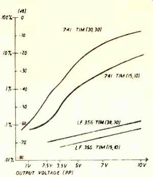
Fig. 9--Peak lo-peak output voltage vs. TIM (30,30) and TIM (15-10)
distortion for 741 and LF 356 op amps.
------------------
Out-of-Band Signals
I would like now to turn to some work I have been doing on phono cartridge measurements and how some unexpected data affects designs.
SMPTE intermodulation and harmonic distortion measurements utilizing a 20 Hz to 20 KHz bandwidth, even using commercial test equipment with a resolution of 0.001 percent, do not fully predict the sonic characteristics of audio amplifiers because, I feel, of their lack of consideration of the sub sonic and supersonic components of the actual signals and how they affect the signal as it is finally audible. One of the major assumptions of TIM theory has been the existence of sufficient supersonic information to provoke this form of distortion [1, 8]. Critics of the TIM concept usually rely on linear assumptions of what should be possible from conventional sources such as musical instruments, disc cutting systems, and phono cartridges [9]. How ever, linear assumptions do not fully predict the actual measurements of many phono cartridges, particularly the moving-coil types.
I would like therefore to present the results of measurements of the super sonic component of the spectrum of several phono cartridges in an effort to ascertain the magnitude of this spectrum portion as well as its subsequent effect on later stages. [10]. For this research, a Tektronix 7L5 spectrum analyzer was used to detect information to 200 kHz, and it was found that certain moving-coil cartridges have significant output even at 160 kHz. While the absolute level of the individual spectra decreases with frequency, the overall envelope of the spectrum closely simulates the TIM (30, 30) waveform (see Fig. 1). (Editor's Note: These graphs were reduced from 'scope photos.) There are notable deviations from "worst case," as shown by the spectra of the moving-magnet cartridges.
Here, the low mechanical resonance (20 kHz) and high series inductance (720 mH), together with the recommended termination capacitance (400 pF), significantly filter the spectrum above 40 kHz (see Figs. 2 and 3). This filtering effect contrasts with the out put of the Denon 103S, with its Shibata stylus, and the GAS Sleeping Beauty (conical stylus), both of which are moving-coil types and have significant energy to 160 kHz (see Figs. 4 and 5). A comparison between square-wave rise time and sine-wave mistracking implies that in many cases cartridge mistracking is a major factor in creating "worst case" dv/dt (see Figs. 6 and 7).
Virtually all difficult material from records, such as cymbal crashes, brass ensembles, and special effects, con tributes significant output to the supersonic spectrum. Applying the TIM (30, 30) waveform (see Fig 8) to a phono preamplifier using a UA741 opamp with a slew rate of 0.6 V/uS showed measureable distortion, even at moderate levels. Other IC op amps with higher slew rates and greater gain-bandwidth products showed essentially un-measureable distortion in the same circuit at moderate levels (see Fig. 9).
Other Distortion Sources
Besides the distortion created by slew-rate difficulties, non linear elements, such as ceramic capacitors, can create distortion if used as low-pass filters or lead networks. In many instances, conventional 20 Hz to 20 kHz measurements fail to assess the actual distortion because at the usual audio frequencies, the capacitors are usually sufficiently decoupled. How ever, with increased spectral bandwidth, such as might be energized with some of the cartridges discussed above, the distortion from these capacitors can dominate an otherwise low-distortion design (see Table I).
The last generally neglected factor I would like to discuss is the spurious subsonic information created by record warps and by tonearm-cartridge mechanical resonances. This has been well documented by other sources [11, 12].
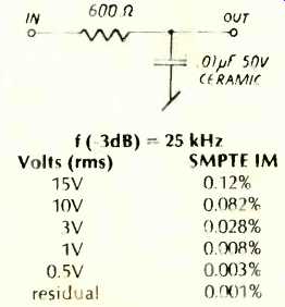
Table I--SMPTE IM distortion of a low-pass filter using a ceramic capacitor.
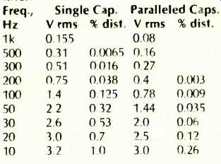
Table II--Harmonic distortion of a tantalum capacitor used as a high-pass
filter.
One consequence of this subsonic information is the distortion caused by electrolytic capacitors when coupling between stages with zero d.c. potential across the terminals. Back-to-back coupling or non-polar tantalums will reduce this distortion, but will not eliminate it completely. One effective compromise is to place two tantalum capacitors side by side in reverse phase. This doubles the capacitance while effecting a first-order cancellation of the distortion in the capacitors. (see Table II).
I hope, then, that some of this data will be useful to other designers, as I have found it a too common assumption that only those signals and distortions within the 20 Hz to 20 kHz band are worth worrying about. I hope too that I have shown that conventional audio measurements do not fully characterize the distortion of a particular audio stage in real-life applications and that measurement of supersonic and subsonic spectra should be considered in a full description of actual circuit performance.
--John J. Curl, Berkeley, Calif.
References:
1. E. Leinonen, M. Otala & J. Curl, "A Method for Measuring Transient Intermodulation Distortion," I. Audio Eng. Soc., Vol. 25, No. 4, April, 1977, p. 107.
2. M. Otala & I. Lammasniemi, "Intermodulation Distortion in the Loudspeaker-Amplifier Inter face," presented at the 59th Convention of the Audio Eng. Soc., Hamburg, 1978, Preprint No. 1336.
3. S. Takahashi & S. Funada, "Envelope Distortion in Audio Amplifiers," presented at the 60th Convention of the Audio Eng. Soc., Los Angeles, 1978, Preprint No. 1344.
4. “Technical Information," Yamaha C-2 owner's manual.
5. J. Hiraga, "How Turntable Mats Influence Sound Quality" Hi-Fi News and Record Review, Vol. 23, No. 4, p. 57, April, 1978.
6. R. C. Heyser, "Perspectives in Audio Analysis: Changing the Frame of Reference, Parts I and II." J. Audio Eng. Soc., Vol. 24, Nos. 8 & 9, pp. 660 & 742, Oct. & Nov., 1976.
7. M. Gerzon, "Mathematics and Sound Perception," Jour. Audio Eng. Soc., Vol. 26, No. 1, p. 46, Jan.-Feb., 1978.
8. M. Otala & E. Leinonen, "Theory of Transient Intermodulation Distortion," Trans. Acous., Speech, & Signal Processing, Vol. ASSP-25, No. 1, Feb., 1977.
9. M. Davis, "Letters to the Editor," The Audio Critic, Vol. 1, No. 4, p. 10, Sept., 1977.
10. D. Hadaway, BAS Speaker, Vol. 5, p. 13, Feb., 1977.
11. I.. Happ & F. Karlov, "Record Warp and System Playback Performance, Jour. Audio Eng. Soc., Vol. 24, No. 8, p. 620, Oct., 1976.
12. T. Holman, " Dynamic Range Requirements of Photograph Preamplifiers," Audio, Vol. 62, No. 7, p. 72, July, 1977.
(adapted from Audio magazine, Sept. 1979)
Also see:
Forum (AM Clear-Channel Proposal) (May 1979)
Forum by Tomlinson Holman (Feb. 1980)
Forum by Leonard Feldman (Jan. 1986)
= = = =