EVERYTHING IN MODULATION
Frankly, I am encouraged. It wasn't so long ago that people were largely mystified by digital audio technology; a vague notion of ones and zeroes constituted their universe of knowledge. Today, perhaps thanks to the rapid proliferation of the Compact Disc, everyone's an expert.
Last week, when a little kid with a portable CD player was in the pause mode, I asked him how all that music is squeezed onto such a small disc.
"Eight-to-fourteen modulation, of course," he answered as he kicked my left shin, hit the play button, and moved away as if afflicted by a rhythmic nervous disorder.
Well, obviously the brat had read my June column about EFM, but maybe he had missed an important point. While EFM is used specifically to encode the pit information on a CD, it occurs within the larger context of the granddaddy of digital audio coding, pulse code modulation (PCM). The vast majority of digital recordings were originally mastered on PCM digital audio recorders, and at the output of a CD player, at the D/A converter, the data momentarily returns to its PCM birthright. We'll look at PCM this month, and next time progress to PCM derivatives such as delta modulation.
Modulation is the process of encoding source information prior to transmission or storage. In general, a carrier signal forms the basis of the channel, and the source information itself merely affects the carrier's parameters. For example, in amplitude modulation (AM) the carrier's amplitude varies relative to the information's amplitude at a rate relative to the information's frequency. In frequency modulation (FM) the carrier's frequency changes by an amount relative to the information's amplitude, again at a rate relative to the information's frequency. Your radio receiver is given the task of demodulating the carrier and outputting the original information. In AM and FM both the modulation and the modulating signal are continuous; they are classified as wave-parameter modulation schemes.
When the original information is digital, the carrier also is digital, and the nature of the modulation is altered.
Two classifications of digital modulation are commonly employed. The first, pulse parameter modulation schemes, are hybrid in nature; a parameter of the transmitted pulse carries the information by varying as an analog of the original signal (Fig. 1). This is most easily seen in pulse amplitude modulation (PAM), in which the varying amplitude of the signal pulses visibly echoes the varying signal amplitude. (PAM forms an important intermediate waveform in digital audio systems, where the audio signal exists as a "staircase" PAM waveform just prior to A/D conversion and immediately following D/A conversion.) In pulse position modulation (PPM), the signal amplitude for the sampling instant encoded by each pulse is represented by the pulse's position within its timing interval (the clock pulses along the bottom of the graph). In pulse width modulation (PWM), signal amplitude is indicated by the width of the pulse.
The other basic classification, numerical pulse parameter modulation (Fig. 2), is purely digital; that is, it encodes the numerical value of the signal amplitude at each sampling instant, rather than the amplitude itself. In pulse number modulation (PNM) a pulse count is used to encode the value of the information; in pulse code modulation (PCM) the waveform itself encodes the binary digits. Both of these techniques readily lend themselves to encoding and decoding by digital circuits, but PNM is plagued by bandwidth problems; a large number of pulses is required to encode a high resolution signal.
PCM neatly overcomes this problem.
Since the binary code itself is retained, the required bandwidth is much narrower. A full-scale, 16-bit amplitude would require only 16 ones. In addition, the coded signal is fully compatible with digital circuits, which are usually designed to operate with a binary code. Because of its highly efficient use of bandwidth and its compatibility with off-the-shelf circuitry, PCM has proved itself to be the ideal choice for digital audio. It is an especially efficient means of representing audio data during recording or reproduction signal processing. When it comes to storage on magnetic tape or optical disc, other forms of modulation (e.g. EFM) may be more efficient.
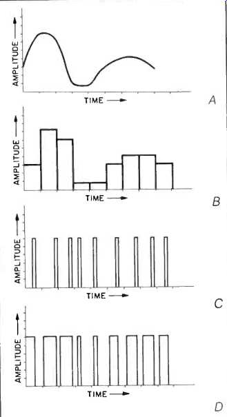
Fig. 1--Three types of pulse parameter modulation: Pulse amplitude modulation
(B), pulse position modulation (C), and pulse width modulation (D). All are
based on the same analog waveform (A).
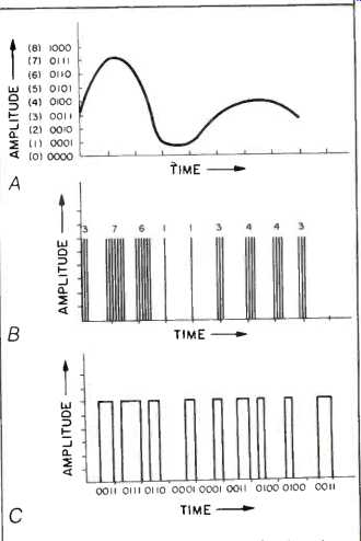
Fig. 2--Two types of numerical pulse parameter modulation: Pulse number modulation
(B) and pulse code modulation (C). Both are based on the numerical values obtained
by sampling the analog waveform (A); amplitude values are indicated in binary
form to its left.
Pulse code modulation is especially handy when confronting the essential problem of an audio digitization system: The conversion from analog to digital and back again. When the analog audio signal is sampled, and an analog value is held by the sample-and-hold circuit to form a PAM waveform, quantization must document the instantaneous amplitude of the stair step and generate a binary data word o be stored. PCM uniquely solves the problem by creating the required binary code directly at the output of the A/D converter. Similarly, the D/A converter will directly accept PCM data and convert it to a PAM waveform. To ice the cake, PCM data is easily multiplexed--that is, several channels of data may be merged to form one. Fig. 3 shows the entire PCM ND encoding process of analog inputs, PAM signals, PCM encoding, and multiplexing.
Given a converter with word length of "n" bits, 2" unique code words are created to represent amplitude values.
For example, a 16-bit system would encode 65,536 amplitude intervals. In the simplest incarnation, binary 0000 0000 0000 0000 would represent decimal 0, and binary 1111 1111 1111 1111 would represent 65,535. In practice, however, that might not be the most efficient mapping of the audio waveform; for instance, the signal is typically bipolar, and the PCM data would not reflect this. Thus a different arrangement of data might be used.
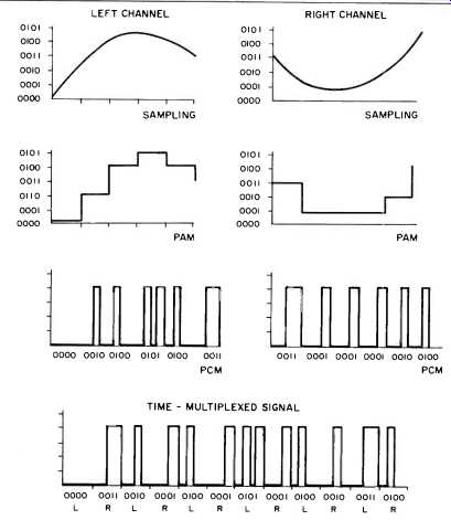
Fig. 3--A complete PCM A/D encoding process: PAM conversion, quantization
and conversion of PCM, and multiplexing of the left and right signals into
one bitstream.
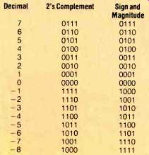
Table 1: Comparison of 2's-complement and sign-and-magnitude binary notation.
Two examples of alternative binary coding are sign-and-magnitude notation and 2's-complement notation, as shown in Table 1. In sign-and-magnitude notation the absolute values of samples are expressed in binary code; their sign is expressed in the left-most bit. In 2's-complement notation two ascending binary counts are used, the left-most bit again representing sign.
More specifically, negative numbers are formed by taking the complement of the positive equivalent and adding 1. For example, the 2's complement of 0100 is 1100 (1011 + 0001). Humans appreciate 2's-complement notation because the left digit always denotes the sign of the number (as it does not in some other notations, not shown here); digital circuits appreciate it because subtraction can be performed with an addition operation, which is simpler.
Many A/D and D/A converters used in audio digitization systems use PCM data in 2's-complement notation to guarantee ease of interface between the converters and the microprocessors and other devices used for signal processing, error correction, etc.
The architecture of a fixed, linear-PCM amplitude scale comprises the classic audio digitization design. However, in the interests of cost or data economy, the fixed, linear design may be modified. For example, to avoid the cost of 16-bit converters a compander could be used; this would make the measuring scale nonlinear. Using techniques similar to those used in analog noise-reduction circuits, the signal could be compressed prior to PCM A/D conversion and expanded after D/A conversion to improve the S/N ratio of a lower-bit word system. In essence, low-level signals would be measured with small increments, high-level signals with large ones.
In another effort to avoid the cost of a long-word A/D converter, a floating-point PCM system, in which the scale is no longer fixed, may be employed.
The binary word may be divided into an exponent and a mantissa, separated by a binary point. For example, in a 3.10 system, a 3-bit exponent would manipulate the gain of the signal prior to a 10-bit PCM A/D converter. By continually adjusting the gain of the signal over 8 (23 = 8) levels, the 10 bits of the ND are always efficiently utilized to maximize the S/N ratio. Of course, to properly recover the signal at the D/A, the 3-bit exponent must again be used to adjust the gain of the signal.
In other applications, such as satellite transmission, data reduction is critical because cost is based on the number of bits transmitted per second.
Most efficient might be a block floating-point design, whereby a 16-bit A/D converter is used to convert a memory block of samples, after which a calculation is made to determine the largest value in the block. Based on that value, all the words in the block are digitally attenuated by a calculated scale factor. Usually the number of bits in the output is much lower than the number of bits originally in the converted block.
The scale factor must accompany the data block for proper rescaling during D/A conversion. Because only one scaling factor is required for an entire block, and the number of bits in the block has been reduced, data reduction is accomplished.
All in all, no matter which binary notation is used or how it is incorporated in the system architecture, PCM is a particularly clever modulation. Its built-in code makes it very slick. In its absence, at the very least, audio digitization systems would be more complex and more costly. To give credit where credit is due, we should note that PCM was originally conceived by Alex Reeves, back in 1937. Thanks, Al.
(adapted from Audio magazine, Oct. 1985)
= = = =