|
|
Following the Selectronic Triphon Quad Amp, and GrandMOS product reviews, Selectronic decided to extrapolate the Quad Amp into a full-range power amplifier with the same amplification module but utilizing a larger power supply. The result is the pure Class-A ProFet amp, available either in a stereo 2 x 15W version or mono 50W (bridged) version. This review features the mono 50W amplifier (the front nameplate with "60W RMS" is an early version of the re-rated amplifier).
The ProFet has no capacitors in the signal path, so any DC voltage offset in your preamplifier will be amplified by the ProFet. If this is a problem, a link capacitor will be necessary (Selectronic advises you to consult your dealer).
Selectronic also advises that the ProFet is designed to give its best performance at a stabilized temperature.
This will be attained after a warmup of 10 to 15 minutes. They suggest that you keep the power permanently on if you are listening to music frequently.
They also recommended not to connect or disconnect anything while the ProFet is operating.
I don't know whether kit versions of the ProFet amplifier are available, as they were with the earlier components. The review samples of the ProFet units were pre-assembled.

PHOTO 1
INSIDE THE AMPLIFIER
Photo 1 shows the front panel, which has only a blue LED indicator to the right of the ProFet name.
The front panel is 9mm thick black anodized aluminum, and the unit is similar in construction to the GRAND MOS, Triphon, and Quad.
The back and bottom of the cross over are constructed of 2mm black- painted steel. Heavy finned aluminum heatsinks are used along each side, and the 1.5mm steel top is perforated to enhance cooling. The unit is very stiff and rugged, even with the top removed. The bottom rails of the heatsink serve as the “feet,” and there is adequate finger space under the unit to easily lift it. The heatsink fins have no uncomfortable sharp edges when you move the amplifier about.
The rear panel (Photo 2) has the IEC power receptacle, a recessed high- quality gold-plated Teflon-insulated RCA unbalanced input jack, an XLR balanced input jack, and a pair of high-quality gold-plated speaker binding posts. The speaker binding posts, in accordance with EU requirements, are not on US 0.75” spacings, so you cannot use dual banana plugs. The third pin of the AC receptacle is connected to the chassis. The power transformer primary was factory-wired for 120V mains.
Photo 3 shows the crossover with the cover removed. The ProFet is a bridge-tied-load (BTL) design. The en tire audio circuitry, including the in puts and speaker jacks, float with respect to the chassis. The large Huiran R-type power transformer occupies the center front of the chassis.
The T-shaped power supply PC board (Manufacturer’s note: The T shaped pcbs are double sided FR4 epoxy with 70um copper) uses eight 10,000uF reservoir capacitors. The power transformer secondary windings and the DC power to the amplifier boards are hard-wired. The power supply transformer uses a Faraday shield between the primary and secondary windings to reduce the inter- winding coupling capacitance.
The two double-sided amplifier PC boards are located along the sides of the unit. Each amplifier board has two JFET drivers with bias adjust pots and two MOSFET output transistors. The capacitors are Wima polystyrene and 1% silver mica types. All resistors are 1% or better metal film. Very little interconnecting wiring is used. Connections between the rear panel speaker binding posts and circuit boards are made with Teflon-covered solid wire.
TOPOLOGY
A schematic was not furnished with the unit, but the topology is described as being similar to the Triphon Quad amp. Indeed, there are only four active parts on each board: two matched TO-92 WET drivers and one each J162 and K1058 power MOSFETs mounted on each heatsink.
A small PC board mounted behind the RCA and XLR input connector board has a Burr-Brown DRV134 balanced line driver IC and two non-polar aluminum supply filter capacitors. The DRV134 is used to convert the unbalanced RCA input to the balanced signal needed to drive the differential BTL power amplifier.
The selection of the desired input is made by means of the miniature toggle switch placed between the two input connectors. The toggle switch selects either the XLR (directly) or the balanced output signal of the DRV134.
The main power supply board contains a total of 80,000uF distributed over eight reservoir capacitors. The ±15V linear regulator ICs for the DRV134 are located on the right rear of the main power supply board.
MEASUREMENTS
Making measurements on the ProFet presented a number of challenges. Neither the input jacks nor the BTL output stage has a common connection to ground or to the chassis, so I needed to work out a ground isolation scheme that allowed me to make measurements on the audio output without shorting one of the speaker connections to ground. Along with that was the concomitant requirement not to introduce excessive hum or noise. My distortion test set has an input ground lift switch, and I ended up using my laptop for the computer based DSO because the desktop computer I usually use eventually makes its way to power line ground through the data cable. In order to monitor things with my analog scope and for some measurements, I needed to use a differential plug-in.
Selectronic recommends that you power the ProFet at least 15 minutes before listening. I operated the ProFet amplifier at low into 8-ohm for one hour. While the ProFet is pure Class-A, the heatsink temperatures increased to only 400 C (104° F). The THD+N reading at the end of this run in period was a bit lower than when I began: 0.52% versus 0.61%. There is only a low-level pop when starting up or shutting down the amplifier.
Output hum and noise measured a low 0.38mV (-84dBr, unbalanced input terminated with 600-ohm) and was inaudible with my ear against the speaker. I also measured -12mV of DC offset, which is quite respectable for a direct-coupled amplifier without a servo circuit.
The low unbalanced input impedance of 10k1 may reduce the LF response of capacitor-coupled output sources or preamps. The balanced XLII input impedance of 1k-ohm is a bit higher than the usual 600-ohm.
The unbalanced input gain at 2.83V RMS output into 4 and 8 loads was 23.1dB and 26.6dB, respectively. The overall voltage gain of the ProFet from its balanced XLII input consistently measured 0.5dB higher than that of the unbalanced input. Because the DRV134 chip has 6dB of gain, this small difference may be due to the 1k resistors at the common arms of the input select toggle switch that loads the DRV134. The ProFet does not invert polarity from either input. The XLII input uses the AES standard pin 2 hot. The output impedance was a high 6R8 at both 1kHz and 20kHz.
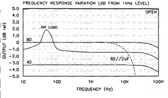
The frequency response (Fig. 1) was within -1dB from DC to 110kHz, at an output of 2.83V RMS at 1kHz into 8-ohm, and wasn’t down -3dB until 317kHz. The response into a 4-ohm load was -3.3dB lower. The response with I a complex load of 8-ohm paralleled with a 2uF cap (a test of compatibility with electrostatic speakers) was essentially the same as the 8-ohm load alone, until 3kHz, where it began a steep rolloff. There was no noticeable problem driving this load.
The IHF speaker load, which has an impedance peak at 50Hz, produced more than 3dB total change in the in- band frequency response. The ProFet amplifier will be quite sensitive to variations in speaker impedance with frequency. Damping factor is just over 1 across the entire audio band.
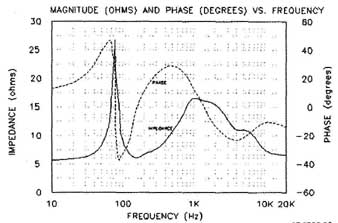
Dennis C. made a good suggestion to perform THD testing with a loudspeaker. As part of my measurements, I connected one of my NHT SuperOne satellites through 6’ of 12 gauge Monster cable. The impedance and phase of the SuperOne versus frequency is shown in Fig. 2.

FIGURE 2: NHT SuperOne impedance and phase
THD+N vs. frequency is shown ix Fig. 3 for the loads indicated on the graph. During distortion testing, I engaged the test set 80kHz low-pass filter to limit the out-of-band noise. I measured all data with the out put voltage held constant. With the resistive loads, the THD is commendably flat over the measured frequency range. The high output impedance of the ProFet produces the roller-coaster THD curves caused by the interaction between the amplifier and the varying impedance of the IHF and NHT speaker loads with frequency.
Figure 4 shows THD+N versus out put power for the loads and frequencies shown in the graph. There was absolutely no strain right up to the point of maximum power. The amplifier reached its 1% clipping point at 53.6W with the 8 ohm load for +0.3 dBW of headroom. It produced only 17.5W with a 4-ohm load and 6.2W with a 2-ohm load at 1% THD, but the THD curves increased gradually until the output reaches the power supply rail limits.
This is more characteristic of a tube amplifier than solid-state. There is also a slight dip part way up each THD curve as the power increases. The negative half-cycles clipped just slightly before the positive half-cycles. The heatsink temperatures remained at 400 C and the AC line current was essentially constant, regardless of the audio power delivered, as you would expect of a Class-A amplifier.
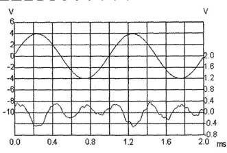
The distortion residual waveform for 5W into 8-ohm at 1kHz is shown in Fig. 5. The upper waveform is the amplifier output signal, and the lower waveform is the monitor output (after the THD test set notch filter), not to scale. This distortion residual signal shows mainly the 2nd and 3rd harmonics overlaid with very low levels of higher harmonics. THD+N at this test point is 0.38%.
TABLE 1: MEASURED PERFORMANCE.

FIGURE 3: THD+N vs. frequency.

FIGURE 4

FIGURE 5: Residual distortion.

FIGURE 6: Spectrum of 50Hz sine wave.

FIGURE 7: Spectrum of 1kHz sine wave.

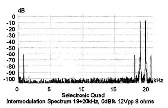
FIGURE 8: Spectrum of 9kHz + 20kHz intermodulation

FIGURE 9: Spectrum of 9khz + 10.05 kHz + 20khz IM signal.
The spectrum of a 50Hz sine wave at 5W into 8-ohm is shown in Fig. 6, from zero to 650Hz. The THD+N here measures 0.41%. The 2nd, 3rd, 4th, and 5th harmonics measure -61dB, -50dB, -89dB, and -80dB, respectively. The calculated THD based on just the first five harmonics is 0.23%. A low-level (-90dB) 60Hz power supply artifact is just present above the noise floor. There is also a 70Hz spike, indicating some intermodulation of the 50Hz test signal with the 60Hz artifact.
The spectrum of a 1kHz sine wave (Fig. 7) had a nearly identical distribution of harmonics, with a THD of 0.38% and a calculated THD (based on harmonics) of 0.32%.
Figure 8 shows the amplifier output spectrum reproducing a combined 19kHz + 20kHz CCIF intermodulation distortion (IMD) signal at 12Vpp into 8-ohm. The 1kHz IMD product is -62dB (0.079%), and the 18kHz and 22kHz products measure -64dB. Repeating the test with a multi-tone IMD signal (9kHz + 10.05kHz + 20kHz, shown in Fig. 9) resulted in a rich distribution of mostly odd-order intermodulation products between -69dB and -77dB, and calculated to be 0.024%. This MIM test gives a better indication of the amplifier’s nonlinear response, because it is a closer approximation to music than a sine wave.
The output response for the 2.5Vp-p square wave at 1kHz into 8-ohm was one of the best I’ve ever seen (Fig. 10). The 40Hz square wave (not shown) showed very little tilt, as you would expect from a fully DC-coupled amplifier. The leading edge of the 10kHz square wave (also not shown) was barely rounded, with no evidence of peaking or ringing. When I connected 2uF in parallel with the 8-ohm load, the leading edge of the 10kHz square wave was quite rounded, reflecting the sensitivity of the ProFet to load impedance (see Fig. 1).
Test Note: Despite the factory recommendation not to connect or disconnect anything while the ProFet is operating, it was necessary for me to do so in order to change signal sources and vary the speaker load during my tests. The ProFet showed no ill effects from any of this switching.
A comparison of the measured results and the manufacturer’s ratings is shown in Table 1.
Also see:
6moons.com/industryfeatures/zen/zen.html
============


