RULE OF THUMB
Congratulations to Ray Alden on his new book, Speaker Building 201 (see review, last issue). The excerpt looks to be masterfully lucid and concise.
I have one small point to make. Unless I am mistaken, the rule that governs the motion of a current-carrying conductor in a magnetic field is Fleming's Left hand rule for motors and not the "right hand rule of vector geometry" as stated in the section dealing with "B--the Gap" in the Oct. '04 issue (p. 23).
Not that it makes a lot of difference to us audiophiles since we don't spend much time listening to DC! I was educated in England, and as my physics teacher (Mr. Williams from Wales) would say, "The way to remember which hand to use is that motors (automobiles) drive on the left, see?" Of course, most of the rest of the world (including Ray in the US) would need to think up a different way of remembering which hand to use.
I look forward to reading the book.
Andre Routh; Medford, N.J.
Ray Alden responds:
To start with, I thank Andre for his kind words and the gentlemanly way in which he posed his question.
I will say more about this at the end of my letter, but first respond to the question at hand.
Initially, I was puzzled by Andre's mention of Fleming's left-hand rule; quite frankly, I was not familiar with it. I poked around some typical American physics books and found references to two different right-hand rules, each used in different contexts. The first was used to determine the direction of a magnetic field produced by a current flowing through a wire. If you wrap your right hand around a wire with your thumb pointing in the direction of the current flow, your fingers will point to the direction of the magnetic field.
However, the rule to which both Andre and I were referring applies to the force produced in motor-like situations. This is the second "right-hand rule" often referenced in American textbooks. It uses three fingers: the thumb, the forefinger, and the middle finger, each placed at right angles to one another.
If the forefinger points to the direction of the magnetic field into which the wire is immersed, and the middle finger to the direction of the current flow in the wire, then the thumb points to the direction of the force applied on the wire. I then discovered references to Fleming's left-hand rule on the Internet and found it does the exact same thing by reversing the alignment of the forefinger and middle finger.
The resulting thumb direction is exactly the same in each case. Andre's mention of driving on the left side in England as opposed to the right side here reminded me of the famous rift caused when differential calculus was simultaneously developed by Isaac Newton in England and Leibniz in Europe. This resulted in the use of one set of symbols for calculus in continental Europe while for centuries England used another. No matter which symbols were used, the mathematics that developed in both cases yielded the same results.
Truthfully, when I received the October audioXpress to find a condensed and excerpt ed first chapter of my book, I was both surprised and a bit apprehensive. After all, readers of audio-Xpress are more sophisticated than the beginners and intermediates for which the first chapter of the book was intended. More complex ideas--or example, the physics underlying a driver's interaction with a box, the use of multiple drivers, or the Bullock-Gonzalez modifications to crossover mathematics--appear in later chapters. I have seen vitriolic letters in both the old Speaker Builder and new audioXpress magazines from self-appointed experts who prefer to tear down rather than pose meaningful questions. Thankfully there are more readers like Andre, who have the humility to say, "I might be mistaken." Such words encourage dialog and inquiry.
OPTO-ISOLATORS
In reference to Jenoë Keceli's "Audio- Optical Isolation Amp" (aX 10/04), I would like to point out that the competitive product from Agilent, the HCNR-200 and HCNR-201, also perform quite well as analog opto-isolators. Agilent and Vi shay have two good application notes on high-performance opto-isolators: AN1357 and Vishay's AN50 . The latter is a good description of unipolar and bipolar applications.
I have found that the linearity of the Agilent devices exceeds the spec cited in their term sheet.
Jack Walton; Short Hills, N.J.
Jenoë Keceli responds:
Thanks for your comment. The home pages you cited can be very useful for further development of the optical isolation amplifier. You can also find applications for differential/balanced amplifiers on the above-mentioned sites. For practical reasons, I used Vishay when I was building the amplifier, but it would be a good idea and experience to try the Agilent device as well. Thanks for your suggestion.
I found Jenoë Keceli's "Audio-Optical Isolation Amp" with the IL300 linear optocouplers (aX 10/04, p. 56) quite interesting. However, I was surprised at the selection of the LM358 op amps for the audio circuitry. Low-performance single supply op amps such as the LM324 and LM358 are just not suitable for audio use.
If you inspect the data sheets, you won't find any specs related to input noise, distortion, slew rate, gain-bandwidth, and so on. The voltage follower pulse response graph on the data sheet shows the LM358 to be severely slew-rate-limited. There are not even any audio circuits in the application examples. That tells you something.
I performed some breadboard tests with one section of an LM358 configured as a unity-gain inverter into a 2k load. While the circuit does meet the 0.05% THD listed by Mr. Keceli at 1kHz and 775mV, the input signal level had to be reduced below 100mV at 10kHz in order not to exceed 1% THD at the output. With a 1V RMS 10kHz sine wave at the input, the output THD was 11%. Viewed on an oscilloscope, the output waveform was triangular at the top, fishhook-shaped at the bottom, and had spurious oscillations at zero crossing. At higher frequencies and levels the output waveform developed a "scoop-out" on the positive half-cycles.
The LM358 also sounds terrible in audio use. Given the availability and low price of pin-compatible dual devices with vastly better performance, the LM358 is not even cost-effective.
Even the mass-market consumer audio favorite, the NJR4560, would be better. However, as a minimum, I suggest the NE5532A or TL072A. These would drop right into the PC board.
There are, of course, even higher-performance modern dual op amps specifically designed for audio use. Search the websites of TI/Burr-Brown and Analog Devices for suitable candidates.
Charles Hansen; Ocean, N.J.
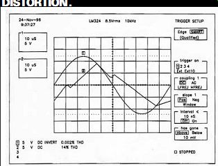
FIGURE 1: LM324/LM358, WAVEFORM DISTORTION.
Jenoë Keceli responds:
Thanks for your interest in my article. I can say that there are, in fact, better Ops than the LM358 (but they might not perform well at low-supply voltage). I tested some for the article, and the results showed that their application at low-supply voltage is strongly limited, especially at higher gain. (This does not show at unity gain you refer to in your letter).
Because my aim was to show how to build a simple isolation amplifier, I opted for the LM358 because of its good performance (Fig. 1) at low-supply voltage.
(This is readily available in my country-- Hungary.) The IC concerned is meant to be used at low-supply voltage. The equipment that the article refers to is not designed for the transmission of 1V RMS.
You could achieve better results with other components, higher supply voltage, and perhaps a full-balanced design, but this would result in another amplifier.
FILAMENT POWER
A.J. van Doorn's latest piece, "Filament and High Voltage Power" (aX 9/04, p. 26), contained a marvelous and provocative bit about "compound (power) control" for filament power. I was a bit skeptical when I saw it, since regulating power precisely entails the use of a multiplier, or some comparable nonlinear element. And in deed the LM317-based circuit shown does not regulate perfectly, but my, how well it does within its constraints! Analysis reveals that it is synthesizing a resistance matched to that of the nominal filament R, in series with a doubled nominal volt age. It is remarkable how well this works, indeed well enough to fairly trounce more complex alternatives. Delightful! Another wise remark suggests placing a positive bias between heater and cathode in low-level circuits, which is rarely discussed.
Brad Wood
A.J. van Doorn responds:
Thank you for the attention and your kind response to my article. Indeed you can control power very well, such as with the power control chip p/n EL4452C available at www.elantec.com. Putting filaments at a positive DC voltage is an old habit that can help if DC for the filaments is too cumbersome.
As you know, voltage feedback produces a low source impedance, and current feedback leads to a high impedance. With a combination of both current and voltage feedback, you can get almost any desired source inner resistance. I experimented a bit with the TDA 7294, a wonderful 100W audio power chip.
With voltage feedback only, the speaker experiences a very low source resistance. With both voltage and current feedback, you can simulate an inner resistance as for a triode amp, which will sound better.
The famous speaker damping factor is a joke. My Tannoys have a 6 ohm impedance and a low DC resistance of about 2 ohm, which is always in series with the speaker cable, so even at zero source impedance, the damping factor isn't that low.
If you like, just put a small 220m-ohm resistor in the speaker return cable and play with current feedback for the best sound. Looking at the A15 tube amp schematics in aX 9/01 ("Glass Shard," p. 93), you'll see a potentiometer named damping control, which controls both current and voltage feedback, as well as the overall gain.
MORE SUB DETAILS
The Tuba 18 Sub (Jan. '05 aX, p. 12) is a project I have been waiting for, but the drawings for the inside panels "A, B, C, D, E, F, G," and so on are incomplete! The Figure 2 drawing has only partial information as to the dimensions.
I would like to build this sub, but without complete panel dimensions I will be unable to do so. Could you please provide me with a source for the missing dimensions?
Bill Hofmeier
Bill Fitzmaurice responds:
Quoting from the article:
"To start construction, cut out the two sides. Draw the locations of all the intersecting parts (Fig. 2) on them, starting with the front, top, back, and bottom, and from there the horn plates, starting at the junction of plate G where it joints to the front. The internal measurements shown are the pathway clearances at each horn bend; the panel dimensions will depend on the actual measured thickness of the material used, as there is no such thing as ½” plywood that actually measures ½” thick." Since the parts are installed sequentially with each part butting into the one before it, the actual dimensions depend on the materials used, and are directly measured off the layout drawn on the cabinet side as each is installed. Otherwise, they could be either too long to fit or too short, leaving gaps between them.
The dimensions listed are all that are required to build the box. They are, in fact, the only calculated dimensions that I used to build the original.
I have been a fan of horns since the original Klipschorn and more than once seriously considered building one. Size and placement requirements have deterred me, however. Thus, I found Bill Fitzmaurice's Tuba 18 extremely en chanting. I most definitely will build one, and have already ordered the driver from MCM. I do, however, have a few questions about the unit's technical details:
1. What is the design frequency of the horn? From the response chart, I would guess somewhere near 40Hz, as peak response is at 50.
2. What flare rate (conical, exponential, tractrix) did you choose and why?
3. What do you consider the throat area?
It appears that the driver fires directly into side "E," so that the throat area would be considered the cross-section al horn area somewhere near the mid point of baffle "A." This strikes me as a really neat way to mount the driver relative to the horn. I can understand the necessity of this arrangement given the size restrictions, but are you aware of any particular advantages/disadvantages of this geometry?
4. With respect to placement, you speak of "facing into a room corner." I would think that you would want the mouth facing out into the room so that the floor and walls form a continuation of the mouth (à la Klipschorn), but looking back at your Tuba 24 article (April '04 aX), I see you specifically talk about firing it into the corner. I suppose that if you placed it a specific distance from the corner, you could get one more "turn" in your horn.
Could you be specific about where you place the mouth relative to the walls and floor of the corner? Maybe even an illustration? Also, I would love to hear why and how this works to extend the horn. Thanks for designing and sharing this great little horn.
Mark Parker
Bill Fitzmaurice responds:
The horn pathway is about 7', so the nominal horn fc when freestanding would be about 40Hz, though corner placement adds another foot and a half of effective path length, so 35Hz would be more like it. The flare is a series of conics, chosen to minimize the cabinet size. The throat technically begins at the point where the cone is no longer firing into the area between parts A and E; the horn pathway prior to that is technically part of the driver front chamber.
With a bass horn there is no disadvantage to the driver mounting topology, as the long wavelengths being passed are omnidirectional. Likewise, frequencies in the passband are too long for the pathway differential between the leading and trailing edges of the cone to cause any phase-related response glitches.
Having the box facing into a corner duplicates a K-Horn alignment, as the final section of the horn pathway and mouth is formed by the outer walls of the cabinet and the room walls. I tried a triangular top à la the Klipsch, which didn't improve response so I didn't use it. My own sub is placed kitty-corner, spaced away from the walls on either side by only the ¾” thickness of the baseboard moldings.
OVER THE YEARS
I am very pleased with the transition to audioXpress from Glass Audio. I find the other articles about speakers and solid state projects interesting and helpful.
I would like to thank the authors who have inspired me to build the equipment that I use today. I have built the head phone amp found in the trial (0/88) issue of Glass Audio. This project by Becker and Oberesch has become my reference system.
I've built the "Peak Reading Level Meter Using Indicator Tubes" (2/95) by Jukka Tolonen. Gary McClellan authored an article, "EZ Start Power Controller" (3/96) that I use on my older tube amps
to help preserve the B+ filter caps and expensive power tubes. Eric Barbour's article, "Improving the SV811-10 Amplifier," (5/97) was a follow-up that includes modifications on an earlier project. This was my first single-ended tube project and proved to be a good match for my Klipsch speakers.
My favorite amp is Joseph Norwood Still's "40W Triode/60W Ultralinear Amp" (2/98), which I keep set up most of the time in my listening room. I also enjoy his later articles in which he experiments with different designs and variations on this amp. I plan on utilizing some of these tweaks on the amp I built from his first article. I have also purchased all the parts to build Mr. Still's "High Quality Control Unit" (aX, March '01) and plan to build this pre amp in the near future.
Peter Millet submitted an article on speakers in audioXpress and briefly mentioned his 813 transmitter tube amp.
He supplied schematics and websites for this amp. I am now acquiring parts to build this, too.
I would like to thank all the authors that take time to document their work and submit them in writing for publication. I admire and respect their expertise and dedication that brings us the articles found every month in audioXpress.
Jim Dungan, Port Neches, Tex.
TRANSFORMER POWER
The power transformer Rick Spencer specified ("A Mini SE Amp," aX April '04, p. 6) handles 269mA of current draw, but the choke specified is rated at 150mA. I have a number of possible transformers I could use, but really need to know what the current need actually is.
Bruce Brown
Rick Spencer responds:
I thank Mr. Bruce Brown for his interest in my project. I am certain that once he has built the amplifier, he will be surprised and pleased with the quality of sound for such a small investment.
You are correct regarding the quoted specs of the transformer and the choke. When selecting the B+ transformer for any project, I like to use one with a power rating that is approximately 25 to 30 percent greater than the circuit will normally demand. This will prevent any overheating of the windings and will, of course, extend the life of the tranny itself.
Sometimes it is difficult to find HV transformers with the proper rating, especially when constructing amplifiers that are capable of very high power output.
Most high power units require separate transformers to supply the various branches of the circuit, such as B+, heaters, or filaments, and even the bias voltage.
The same is true concerning the size of the choke.
If you wish to use choke filtering for all the B+ circuit, then choose a choke that can handle all of the current required throughout the entire circuit. Some of these larger value chokes are quite heavy and have dimensions that are almost the same as some power transformers. On the other hand, some may wish to filter the B+ supplied to the driver tubes only, which may be accomplished with a smaller type of choke.
The transformer I chose for the mini SE amp is perfect for the application. Concerning the load on the B+, if you add up the total draw of all the tubes, you will find that the idle current is only around 110mA and not much more at maximum output.
The Hammond #261M6 is just loafing along at this rating while being used in the choke input filter configuration. The choke is rated for 150mA while maintaining its value of 5H.
This choke, like most others, will have a little less inductance when operated at a DC current higher than recommended and will show a little more when used at a lower current. When I pushed my amp hard during testing (maximum power for periods of ten minutes or more), neither the transformer nor the choke became more than slightly warm to the touch.
I think that all Hammond products are rated very conservatively, and, from my experience, I have never had one roll over and quit! So, as you can see, if you build the amp with a transformer and choke within these stated parameters, you can't go wrong. Just remember to use a good choke for filtering in your power supply, because even with extra large capacitors, some noise will sneak right on by and into your amp circuits, and it will take a good choke to keep your B+ clean. If you still desire a "beefier" choke, then I suggest the Hammond #159S, but you will definitely need a larger chassis than I used.
You stated that you had some transformers on hand. Just remember to keep the B+ that hits the plates of the 12L6s within the 200V range. The Hammond transformer and choke combo that I used gave me the required voltage without requiring any dropping resistors, so perhaps you will be just as fortunate.
Good luck, and enjoy building your version of this neat little amplifier. And, please, write back to audioXpress when you are finished, and let everyone know how it turned out!
============
Also see: