|
|
Follow these vibration-reduction tips to achieve some rewarding audio results.
A manila folder dwelt for a long time in my file cabinet with a hastily scribbled, unimaginative title on the tab — ”Preamp X.” I had started a pre amp project nearly 20 years ago and collected data for that end, but ultimately let the whole affair lie dormant, as I realized that my design ideas weren’t “high end.”
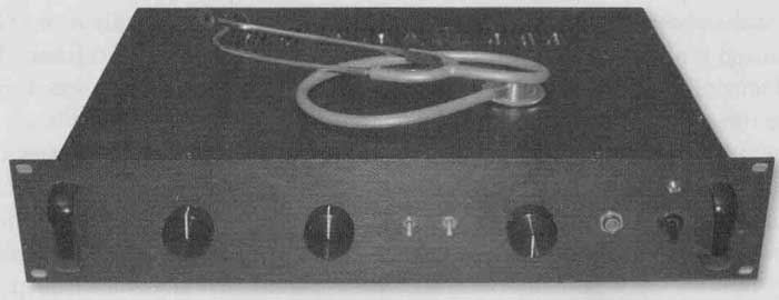
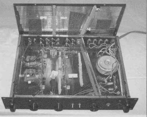
Not so long ago a friend sent me some suggested circuits and parts recommendations which looked very inviting, so after I scrapped old boards and unused documentation and resurrected a half-made chassis, Preamp X was finally born (Photos 1 and 2).

PHOTO 1: Preamp X (with medical stethoscope to detect troublesome noises).

PHOTO 2: Preamp X insides.
This article is not a preamp construction project at all, but rather documents what happened to Preamp X once it began to reproduce sound. I offer excerpts from my log of Preamp X to illustrate the difficulty in properly finishing even a simple piece of electronics in a way that brings out the best of its realistic musical potential.
BASIC FEATURES
Preamp X houses two PC boards mounted on edge. One board contains two op amp phono stages (with inductor RIAA rolloff), while the other contains a pair of op amp line drivers. Separate regulators provide power at each opamp supply pin. The raw supply is located behind a bulkhead to success fully reduce the radiation of noise into the circuitry.
There is a five-way input selector switch, a blue Alps volume control, and similar balance control. Toggle switches provide “muting” and “mono” functions. The preamp was built into a Sunix chassis made of 0.035” steel (six elemental panels) with an aluminum front dress panel. As you can see, in no. way is Preamp X electronically or mechanically unusual, although component selections followed the designer’s exhaustive testing.
FIRST VOYAGE
After the customary startup debugging and tweaking, the preamp came alive and began turning out “promising” sound, meaning I didn’t think the promise was fulfilled. Certain aspects of the music were acceptable, but the mainly bland presentation was far from “live.” So I began a carefully documented witch hunt to determine whether vibration was a factor. (The preamp has always rested on four Sorbothane feet, a practice I ob serve for all electronic components.)
THE LOG
I have separated out the mechanical change items from the current total of 32 entries in the project logbook for the preamp, and repeat them here along with their noted sonic consequences.
Where I underlined my logged comments, upper case is used here. Similar entries accompany the electrical alterations, but those are not the subject of this article.
In many cases I made several physical changes at once, clouding the issue of which produced the most sonic improvement. If I build another pre amp, I would complete all items listed during the initial construction phase, because they all tested successfully. The basic mechanisms I attacked were panel and component resonance and colliding objects:
2. Coat opamps and raw supply caps with lead foil (two layers). Note gains in detail, bass, linearity and clarity.
3. Coat all mating cabinet surfaces with lead foil. Put long strips on top, bottom, side panels. Improvements similar to 2 above.
9. Mount PC board L-brackets to grommeted holes instead of bare chassis metal. Small improvement in clarity.
12. Mount front-to-back ¼” x ½” oak. strips on top, bottom covers (two each) with Gorilla Glue (urethane based).
Add lead foil to power supply bulkhead. Apply remaining scraps of self-adhesive damping “tar paper.” LARGE gains in detail, clarity, overtones, musicality.
15. While open (to replace phono coax cable), add more lead strips, some foam, and rubber pads to combat vibration between the front dress panel and the steel structural panel immediately behind it. Add foam dampers to the long wires running between the input jack and selector switch. MAJOR IMPROVEMENT in sound quality—sense of liveness, purity, dynamics.
It was startling to realize that items 12 and 15 were very successful AFTER adding rubber grommets to the PC board mounts. However, the entire raw supply, controls, and jacks are still hard- mounted except for the foam pad sup plied with the toroidal transformer, so evidently something there is vulnerable. Because the results are in hand, I won’t spend time isolating the culprit(s), but some mystery lingers here.
DOWNSTREAM
The task of Preamp X is to drive a second electromechanical contraption, “Amptron,” another collaboration using the designer’s electronic specifications and my chassis.
Here I figured I had applied my structural lessons from Preamp X, but found that Amptron still needed to undergo the same witch hunt, and that it too reacted strongly to even more sophisticated vibration control than appears here (the subject of another article).
FINDINGS
The inescapable evidence from these fruitful experiments is that electrons should be the only moving parts in an electronic system. This can be trouble- some to achieve depending on how loud the music plays, as I learned while surveying the structures with a medical stethoscope, a very revealing instrument.
The sum total of these modest efforts resulted in a remarkable unveiling of the musical presentation. Actually, I’d rather be telling you that the changes are small and this effort was needless, but the fact is, Preamp X has truly blossomed forth.
============