|
|
An experienced tube tester shows how to ensure accurate measurements.
Tube testers built by the Hickok Electrical Instrument Company have become highly prized for their accuracy and dependability. Originally built for the service industry when vacuum tubes were the foundation of electronics, they continue to be in demand for the much smaller but still active antique radio collector and audio market. In many instances the selling prices today far exceed the original retail price due to the demand and the limited supply. When buying a tube tester it is important to know what you are getting and whether it is worth the cost.
One of the primary markets for tube testing equipment is the online auction service eBay. Many of the testers for sale on eBay and through private venues are advertised as in good condition or as “calibrated.” The meaning of the term calibrated is generally up to the discretion of the seller, who may have tested one tube that read about the same as it did on another similar tester and so assumed good calibration. He may have had it serviced at a shop that reported that they calibrated it. It may even have been adjusted with the standard calibration process using the Hickok recommended 6L6 calibration tube.
Under these circumstances you would assume that the tester is in calibration and everything is working as it should. This is not necessarily true. The traditional Hickok calibration process available on the web and through re print packages of operator’s manuals is probably one of the least understood and most often misapplied documents. While it was adequate in its day, time has changed the conditions that were assumed when this document was written and it cannot compensate for component drift and other errors that are now common.
Even using the Hickok calibration tube, the gold standard of Hickok calibration, will give a false sense of accuracy. The gold has tarnished, so you must employ a much more comprehensive procedure in order to reach the level of accuracy that Hickok intended.
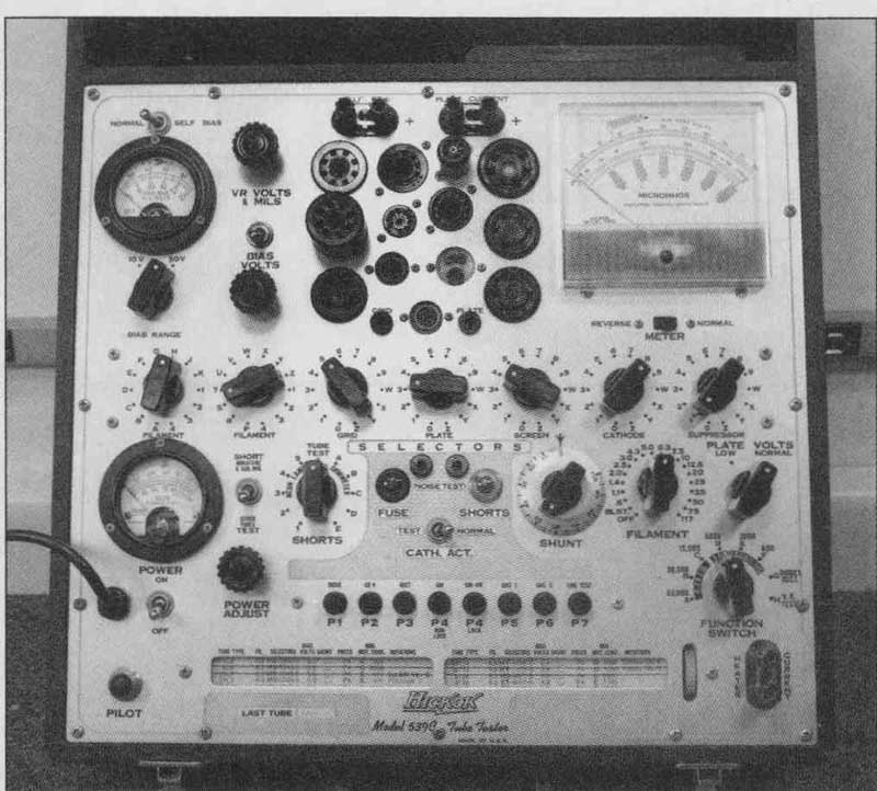
I would like to illustrate this point with a study of one of the most desirable of the Hickok testers, the 539C, which was a high-end tester of better than average functionality (Fig. 1). It was relatively expensive in its day and continues to command high prices. While many of these testers are assumed to be factory accurate, there are several factors you need to consider. My study begins with the investigation of a simple problem of compensating for the inaccuracy of testing tubes with heater hum.
TUBES WITH AC HEATER HUM
While running tests on 6L6 tubes, I came across an interesting problem of zeroing out a shift in the transconductance reading that some tubes have. This shift is a fixed amount of error in the measured transconductance that is added to or subtracted from the actual value of transconductance. A large percentage of 6L6 tubes are prone to have the plate current modulated by the AC heater current even with no signal on the grid, an effect known as heater hum. The Hickok 539C tester is particularly sensitive to this.
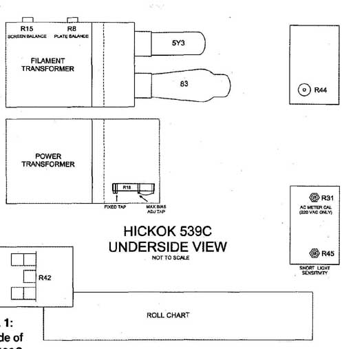
FIGURE 1: Underside of Hickok 539C.
The 539C uses a small 60Hz grid signal in testing 6L6 tubes. Any small amount of 60Hz AC heater hum is added to or subtracted from the grid signal and causes the transconductance readings to be abnormally high or low by a fixed amount. The amount and the direction of the error depends on the amount and polarity of the heater hum with respect to the actual grid signal voltage. If you reverse the AC supply to the heater pins, you will see that the error also reverses.
In order to set up some tests, I replaced two 40 ohm resistors in the center of the 539C measurement bridge circuit with two 30.1 ohm fixed resistors and a 20-ohm 25 turn trimming potentiometer. I connected the potentiometer wiper to the center leg of the bridge. The overall resistance of the bridge remained unchanged, but the center point was now adjustable in order to shift the balance of the metering bridge one way or the other. By doing this you can easily adjust out for testing any fixed error—or offset, as it is called (Fig. 2).
In the course of the tests I measured a 6L6 calibration tube that has a known transconductance and no heater hum. To test the balance of the bridge, I disabled the AC signal to the grid of the tube assuring that the tube could show no transconductance whatsoever. I tested the tube and adjusted the 20 ohm potentiometer for a transconductance reading of zero on the meter to establish’ a base line. This is called nulling or balancing the bridge.
Then I re-enabled the AC grid signal and read the transconductance value, which was supposed to be 5300-umhos, but actually read 6000-umhos. Not a huge difference, but significant enough to warrant correction.
The usual method of calibrating a 539C requires a 6L6 tube with a known transconductance value as determined by a factory-certified Hickok 539C tester.
The calibration 6L6 is measured and R15 is adjusted to match the reading on the tester to the known transconductance of the tube. R15 is a potentiometer located on the positive output of the 5Y3 rectifier, which supplies DC for the control grid bias and the screen grid.
I followed that procedure with my calibration 6L6 and adjusted R15 for the correct reading. Then I followed up by re-zeroing the bridge to null as before with the 20-ohm pot.
When I measured the tube again, the reading was exactly 6000-umhos just as before. On a hunch, I set R15 to the limit of rotation, balanced the bridge, and took a reading. Once again it was 6000. I ran R15 to the other limit, balanced the bridge, and took a reading. Again it was 6000.
What was happening is this: To what ever setting Rl5 is adjusted, the act of independently readjusting the bridge perfectly negates any imbalance in the R15 setting. This indicated that R15’s primary function is to balance the 5Y3 screen and bias power supply so there are no fixed offsets in the transconductance readings. R15 is not able to trim the actual transconductance calibration, although Hickok used it for that purpose. This was a trade-off against all of the other characteristics of the tester being close to correct and using R15 to fine-tune the remaining error.
Once the bridge circuits are balanced, the transconductance readings depend on the value of the resistors in the meter bridge circuit and the level of the 60Hz grid signal applied to the tube under test. The transconductance measurement accuracy of the bridge is easy to check using the standard transformer isolated current source test circuit (Fig. 3).
I set up the tester for a 6L6 and attached the test circuit to pins 3 and 8 of the octal socket, corresponding to the plate and cathode connections. The circuit applies a constant 60Hz AC voltage through a fixed resistor to add a known constant AC cu to the DC plate current, much as a tube would. The amount of AC current added translates directly to a value of transconductance as read on the meter. If you know the amount of AC current added, you can calculate what the resulting transconductance should read.
With this test, all of the scales on my 539C read correctly. If they had not, then one or more of the meter bridge circuit resistors would have needed to be replaced. Because the transconductance ranges were reading correctly, I checked the grid signal. I found that it was inordinately high, making the transconductance readings high also. This is where the error originated. I go into more detail on this later.
CALIBRATION CIRCUIT
Transconductance is defined as the change in plate current divided by the change in grid voltage. The unit is called a “mho,” which is simply the term “ohm” spelled backwards because a mho is the inverse of an ohm. Simply put, the transconductance of a tube is measured by applying an AC signal to the grid and measuring the resulting AC current on the plate. The higher the AC plate current for a given AC grid voltage, the higher transconductance the tube has.
Calibration of the circuits that mea sure the transconductance consists of testing and adjusting all of the various factors that affect the final readings. In addition to the measurement circuits, other considerations such as DC bias and filament voltages are important for proper readings. You can easily test these values by following a standard calibration procedure, but I won’t digress into that.
You must consider five aspects of the transconductance calibration. First is the balance of the metering bridge circuit, which measures the plate current and is made up of the meter and associated resistors. It is sensitive to the amount of AC added to the DC current.

FIGURE 2: Replace R39 and R40 with resistors and pot.
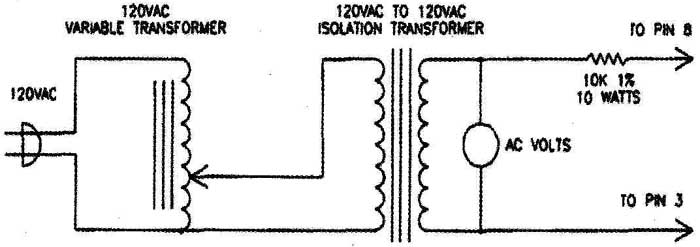
FIGURE 3: Transconductance measurement test circuit.
Metering balance is directly affected by the degree of matching of the resistors in the metering bridge. Unbalances in the bridge circuit show up as fixed positive or negative offsets to the transconductance readings. The better the match of the resistances in opposite legs of the bridge, the lower the error will be.
Proper metering balance is tested by allowing a DC plate current having no AC component to pass and verifying that the transconductance reads zero. I do this by connecting a 10k resistor from the plate to the cathode pins on the octal socket and performing a standard transconductance test. If the metering bridge is balanced, the reading will be zero. Hickok provided no means of directly balancing the bridge. If the bridge is unbalanced, the resistor values in the bridge circuit have drifted off and you must replace the resistors.
The second factor is the sensitivity of the metering bridge circuit. This is the amount of deflection of the meter for a given value of AC plate current. The greater the sensitivity of the bridge to AC plate current, the larger the deflection of the meter. The amount of deflection depends on the value of the resistors in the bridge and the sensitivity of the meter movement. Larger values of resistance make the bridge more sensitive.
You can test the sensitivity of the transconductance metering by using the standard transformer isolated current source test circuit. Hickok provided no means of directly adjusting the sensitivity. If the transconductance readings are incorrect, the resistor values may have drifted off and you must replace the resistors. The meter itself is also not immune to change and should be tested for full-scale sensitivity.
Third is the 83 mercury rectifier tube power supply, which supplies the DC plate voltage. The output of the 83 is unfiltered 120Hz pulsating DC. The plate voltage supply must be constant such that all of the pulses are of equal amplitude. If they are not, then the bridge measures the unequal amplitudes as a 60Hz plate current signal. This will add a fixed positive or negative offset to the readings.
Fourth, the 5Y3 rectifier tube supplies the DC voltages for the control grid bias and screen grid bias. Just as with the 83, the output voltage from the 5Y3 rectifier must be balanced. Unequal 120Hz pulse amplitude adds a 60Hz AC signal to these bias voltages. AC added to the DC bias will cause both offset and transconductance errors.
The fifth factor is the AC grid signal voltage. The AC grid signal is the test voltage that the tube amplifies so you can measure the transconductance. If the signal voltage is higher or lower than the correct value, the transconductance will also read higher or lower than it should.
ADJUSTMENTS
In the conventional calibration process, for a proper reading you adjust the calibration control R15, which is a potentiometer placed across the filament of the 5Y3 rectifier. The DC output from this rectifier is taken from the wiper of R15. By adjusting the wiper off center one way or the other, it is possible to shift the balance of the DC output from the
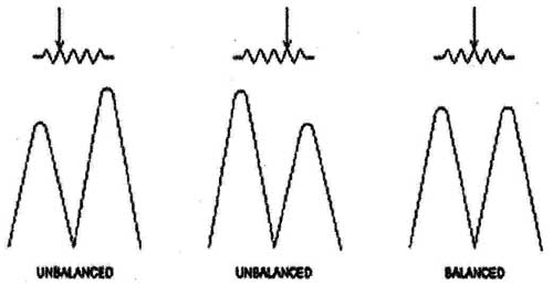
FIGURE 4: Adjustment of R8 and R15 for balance.
Call now to speak to one of our knowledgeable salespeople or browse our extensive online catalog two plates of the 5Y3. The relative alternate peak values of the 120Hz pulsating
DC output can be changed with respect to each other and adjusted until they are equal.
The secondary result of this adjustment is a variable level 60Hz signal added to the 120Hz pulsating DC bias. Ideally there should be no added AC, and this control is provided so that any residual AC present can be adjusted out (Fig. 4).
Hickok uses R15 as a primary calibration adjustment to compensate for any imbalance in the 5Y3 rectifier output to zero out fixed errors. This works fairly well as long as the grid signal voltage is close to the correct value and the metering circuit is already close to balance. While this may have been true when the tester left the factory, after years of use resistor values drift and the conventional calibration process becomes increasingly inaccurate because one calibration control can no longer adequately compensate for three different diverging quantities. Other factors have crept in and the adjustment of R15 alone will no longer suffice.
Zeroing the offset in the transconductance readings using R15 does not necessarily calibrate the tester. If the meter bridge circuit is slightly out of balance, adjusting R15 to obtain a correct reading will correctly compensate the bridge balance, but it will also introduce errors by adding an artificial AC component to the DC. Bridge balance must first be correct independently of the R15 adjustment.
Adjusting R15 to match the transconductance of a calibration tube, as Hickok describes in its standard calibration notes, does not necessarily accurately calibrate the tester either. My initial tests on the 6L6 calibration tube proved this. When I adjusted R15 for proper balance, this caused the calibration tube to read the wrong value.
When I adjusted R15 for the calibration tube to read correctly, this left the tester unbalanced, because the grid signal voltage, which is fixed and assumed to be correct, had changed. Adjusting R15 made the calibration tube read correctly, but that’s about the only tube that would because now the balance was effectively misadjusted to cover up the error in the grid signal voltage. A seemingly calibrated tester that reads a 6L6 calibration tube correctly could be very far out of calibration for every other tube tested and you would not know it.
R15 corrects for errors in the AC grid signal by artificially adding an AC signal to the DC grid bias. The problem with this is that the DC grid bias voltage is adjustable. Various tubes use different bias settings for testing.
As the DC bias is changed up and down, any AC component on the bias voltage changes up and down along with it, effectively changing the AC grid signal for every adjustment in bias setting. The AC grid signal must be constant for any bias setting. Any errors in the grid signal must be corrected directly at the source so that they are constant and not subject to change by other functions.
Unbalance of the 5Y3 rectifier also adds an AC component to the screen supply, causing a constant shift in transconductance readings for tubes with screen grids. The actual best position for R15 is not simply where the calibration tube reads its published value, but rather it is the position where the unfiltered DC voltage has all of the peaks of equal amplitude and therefore no added AC component. Balancing the supply directly is more complicated than adjusting for a simple meter reading. It requires the use of an oscilloscope to observe the peaks of the rectified DC to determine whether they are of equal height.
The other calibration control is R8, a potentiometer placed across the filament of the 83 plate supply rectifier similar in function to R15 for the 5Y3 rectifier. This control balances out any difference in the peak values of the pulsating DC for the plate voltage. Balancing the 83 rectifier has a similar but smaller effect on transconductance readings in that it trims out fixed offsets caused by any imbalance in the plate supply voltage.
The conventional calibration procedure for R8 is to set up the transformer isolated current source test circuit and apply a standard signal to the tester. You set the transconductance range to its most sensitive setting and adjust R8 until the transconductance reading is correct for the test current applied. This method assumes that the measurement bridge is already balanced and has the proper sensitivity.
Adjusting R8 will properly balance the plate supply if this is true. If it isn’t true, then R8 can compensate for an unbalance in the bridge but it will also cover up errors in the sensitivity. A better means is to balance the plate supply directly using an oscilloscope and then correct any bridge errors by replacing drifted resistors.
There are two separate sources of voltage on the control grid: the adjust able DC bias from the 5Y3 rectifier and the AC grid signal voltage. The AC grid signal is a constant voltage, derived from a dedicated winding on the power transformer and scaled down to the desired levels by a set of fixed value resistors. Different fixed voltages are used de pending on the transconductance range used for the test.
The AC grid signal is used to provide the change in grid voltage to measure the transconductance of the tube under test. There is no means to adjust the AC grid signal voltage for calibration, the assumption being that the voltage as de fined by the transformer and the divider resistors is correct and will stay that way. Because Hickok provided no adjustment for grid signal voltage, the only means to correct an error is to replace resistors in the grid signal divider circuit in order to get the proper voltages.
PRACTICAL CALIBRATION
Now you can see why adjusting R8 and R15 alone is not adequate, especially considering the aging of components. You can obtain a correct reading with a calibration tube, but it does not necessarily mean the tester is calibrated. You need to separate and test each of the functions that affect calibration. In order to do that a different calibration method needs to be followed that verifies and corrects each of the five points I made earlier.
Adjustment of the power supply balance is already provided by R8 and R15. To correct the grid signal voltages, you must measure and replace the resistors in the grid signal resist9r divider chain with the proper values. In addition, you can add a variable resistor to the grid signal divider circuit so you can measure and trim the voltage. You must calibrate the meter bridge sensitivity and balance by testing and replacing the bridge resistors. For my tests I had already provided an independent adjustment of the meter bridge balance by replacing two of the metering bridge resistors with two smaller value fixed resistors and a potentiometer.
To provide a means of adjusting the AC grid signal, I replaced the 500-ohm fixed resistor in the signal divider with a 402-ohm fixed resistor and a 200 ohm 25 turn trimming potentiometer. This arrangement allowed adjustment of the transformer voltage to set the signal voltages at the correct value. If any of the other resistors in this divider have drifted off value, you must replace them with new ones of the design value shown. That way all the various signal voltages will be correct once the main adjustment is made (Fig. 5).
I modified my own 539C tester with these changes and followed an alternative calibration procedure that utilizes them. Briefly, I balanced each of the power supplies first using an oscilloscope to display the peak values of the pulsating DC. I balanced the meter bridge by passing the balanced DC plate current through a 10k resistor connected from the plate to cathode connections on the tester’s octal socket. Finally, I adjusted the grid signal to factory specification.
For a complete test and calibration, you should examine other aspects of the tester and verify them to be correct. Most of the conditions in my 539C were already verified to be correct when I was performing the 6L6 tests. I could have used the calibration tube for the final step, but for the trial test I wanted to see how successful the calibration would be without its use. My follow-up test using two calibration tubes tested and certified on two independently calibrated 539C testers verified that my 539C read them both correctly. Even if the other testers were not balanced properly, the calibration tube value should still be valid as long as they both were calibrated on a good known 6L6 calibration tube. Balance errors would cancel for that tube alone.
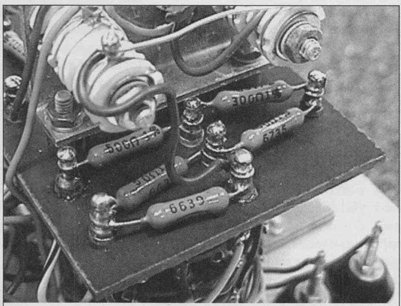
PHOTO 3: Original grid divider.
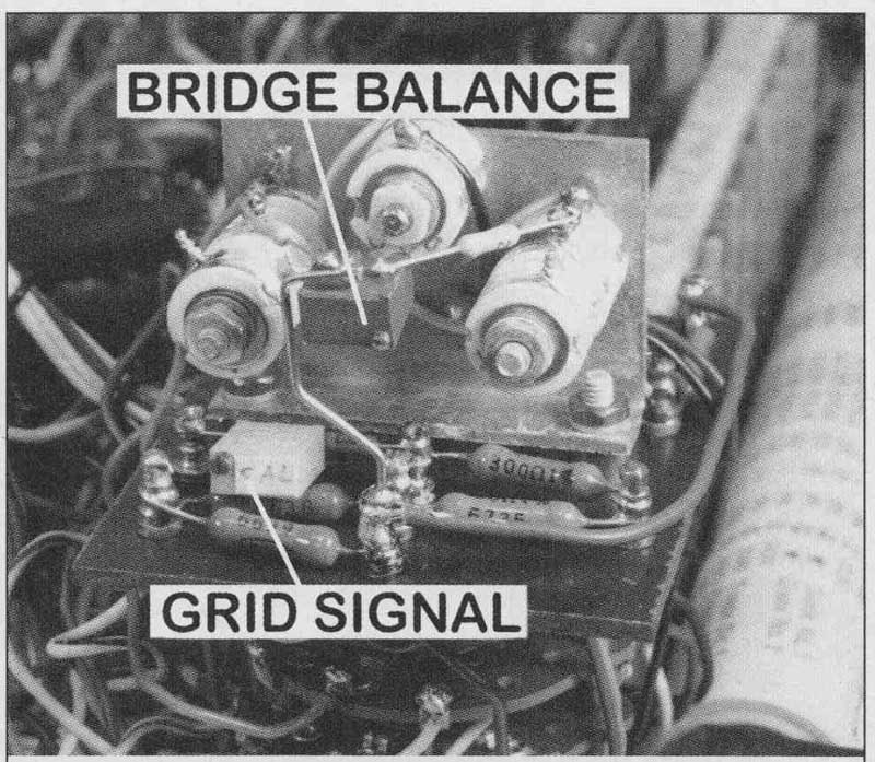
PHOTO 4: Modified grid divider.
OTHER HICKOK TESTERS
These same principles apply to the other models of Hickok testers. The smaller service type mutual conductance testers such as the 533A, 600A, 800A, 6000A, and others all operate on the same basic circuit of a balanced bridge.
The “ENGLISH” or “SHUNT” control in the smaller Hickok testers are the actual transconductance meter bridge resistors. As you turn the control clockwise, the two halves decrease in resistance by the same amount, thereby decreasing the sensitivity of the bridge so that higher transconductance readings are displayed without over-scaling the meter. The resistance of both halves of the control must track each other as they are rotated or the bridge will become unbalanced, adding or subtracting a constant number from the correct reading. The constancy of this balance and the accuracy of the transconductance readings at any setting across the entire length of rotation are entirely dependent on the quality of the potentiometer.
The usual field calibration method for the smaller Hickok testers with a variable ENGLISH or SHUNT control is simple. The ENGLISH control is set to the orange dot near the 73 position on the dial. This sets the meter scale to the 3000-umho range. The standard isolated current source test circuit is connected and a calibrated test signal is applied to the tester.
The two sections of the ENGLISH control are mechanically uncoupled and one is rotated with respect to the other until the transconductance reads correctly on the meter. The actual resistance of the transconductance circuit is not changed. The only change is the matching of the resistance of one leg to the other. This simply adjusts the balance of the metering circuit bridge until the transconductance reading is correct for the signal applied. The assumption is that the resistance of the control is already pretty close to correct and only the balance needs trimming. For a ser vice type tester this is a reasonable assumption.
If the potentiometers were high quality and consistent, you could simply adjust the controls for perfect balance and the calibration would be correct for any setting of the dial. In practice this does not always work for several reasons.
First, the balance of the two halves of the control is never perfect over the entire range of rotation. As the control is rotated, the two halves don’t necessarily track each other well, especially at the ends of rotation. This adds both positive and negative offset errors de pending on the setting of the control. The best you can do is balance to the true average over the entire rotation and make the maximum positive and negative variations as minimal as possible. This is a difficult and time-consuming process that results in little better overall accuracy than if you had simply calibrated at one point.
Second, some controls are mechanically sloppy and changing the direction of rotation will also change the balance. You can fix this by taking the control apart and solidly fixing the wiper assemblies to the shaft so they cannot change relative position as the direction of rotation is reversed. Usually a small drop of epoxy or urethane glue will take care of that.
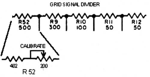
FIGURE 5: Replace R52 with series resistor and pot.
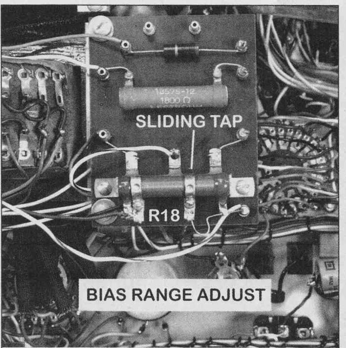
PHOTO 6: Bias range adjust R18.
Third, when the two halves are adjusted where they are reasonably balanced for most of the rotation, the control does not necessarily have the correct resistance to match the orange dot markings on the ENGLISH dial. If you adjust the control for best balance and then follow with the usual calibration circuit test, the meter reading will not necessarily be correct. Only when both halves of the potentiometer track closely enough are the balance and calibration correct for every setting. For many potentiometers this won’t be true. There is always going to be more error at some settings than at others.
The standard procedure of matching the transconductance reading to the calibration circuit signal is no better than adjusting for best balance. The only advantage is that for at least one known setting on the ENGLISH dial the measured transconductance reads correctly for the tester. You can use this as a reference of sorts to verify later that the tube tester is still working properly.
In the standard Hickok calibration neither the balance of the grid bias supply nor the grid signal voltage is taken into account. There is no way to adjust it if it were. As long as there are no component failures, this is probably ad equate given the intended purpose that these testers are designed for.
While the smaller testers have no provision for field calibration or power supply balancing, you can check calibration and troubleshoot by looking at the plate and grid DC supply voltages and determining whether they are at the correct levels, are balanced, and whether the AC grid signal voltages are correct. Because there are no adjustments, power supply balance in these testers primarily depends on the condition of the rectifier tubes. Voltage levels depend on the AC line voltage and the circuits that perform the AC line test.
The two main determinants of the transconductance calibration are the position of the ENGLISH control and the AC grid signal voltage. After the control is adjusted for balance, there is nothing else that you can do to it. Adjustment of the grid signal is not as easy as with the 539C because the smaller testers derive the grid signal directly from the power transformer with no resistor dividers that you can replace or adjust. If the power supplies are properly balanced and there are no other problems, the best you can do is apply the typical calibration process and leave it at that.
The ENGLISH control is not a precision device. Some error is to be expected. If you test the transconductance calibration at the 3000 setting on the ENGLISH control using the test circuit and then set the control to the 6000 setting, it won’t read the same transconductance on the 6000 scale. The 15,000 scale won’t read the same either.
If it is way off and there are no other problems in the tester, the only cure is to replace the control. Most likely a degree of error was always there and was considered acceptable performance for the purpose for which a ser vice type tester was designed and sold. The purpose of most tube testers is not to quantify the actual performance of individual tubes but to segregate the probable good ones from the probable bad ones in the process of equipment service and repair. If it were otherwise, the manufacturer would not have put a REPLACE-?-GOOD scale on the meter.
As a closing note, I solved the 6L6 heater hum problem. Rather than go through complicated tests or making changes to the tester, I use a simple method to subtract off the offset. I test the sample 6L6 in the usual way, note the transconductance reading, change the heater settings from H S to C X, and test again. Doing this reverses the connections to the heater.
If the two readings are the same, there is no hum. If they are different, I take the average by adding the two readings and dividing by two. This cancels out the offset and results in the true transconductance as measured by a Hickok 539C.
============
