This author reveals a neat method to achieve a 40W per channel stereo amp.
After I put together a home theater system, I realized that I needed seven channels of power amplification, so I decided to build my own. I’ve built a number of amplifiers in the past and struggled with many problems including reliability, stability, critical bias adjustments, and so on. Having built a low power amp based on National Semiconductor’s LM12 power operational amp with good results, I decided to build higher power amps based on it.
CIRCUIT FEATURES
This amplifier circuit, which uses the LM12, is an integrated circuit power amplifier in a T03 package capable of delivering 80W of power and 10A of current with a ±30V power supply (Photo 1). It has a number of important built-in features including thermal limiting, current limiting, and dynamic safe-area protection. Besides its high power capability and ease of application, it has a slew rate of 9V per microsecond, which in National’s words, “virtually eliminates transient TIM distortion.”
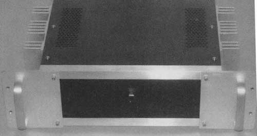
PHOTO 1: Author’s LM12-based amp.
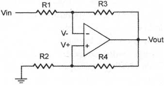
FIGURE 1: Simplified version of LM12 stage.
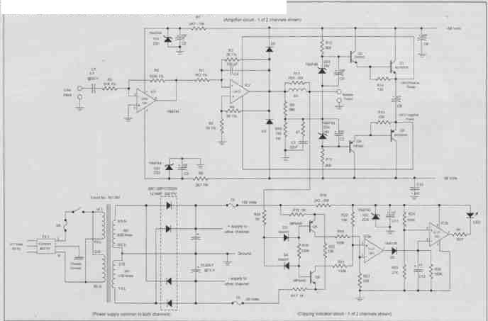
FIGURE 2: LM12-based amp circuit with clipping indicator.
In its simplest implementation, as de scribed in National’s application note 446, it is meant to drive a 4-ohm load but it has a gain of only 3. In order to get a higher gain and greater voltage swing and significantly higher power levels, the same application note outlines a circuit using a cascode technique by which the supply voltage to the LM12 tracks the output voltage, thereby keeping a constant lower voltage across the device. This amp is an adaptation of that circuit.
The power supply for the amp that I have configured is ±56V, which requires this cascode technique. The amp described in National’s application note, while looking great, has a couple of shortcomings: It has a non-standard inverting output and the input impedance is too low for many preamplifiers.
In order to compensate for these, I added an input buffer that inverts the signal and raises the input impedance to approximately 50k-ohm. I also added a clipping indicator circuit that was designed by Rod Elliott and described in his Project 23 publication. I have included a complete schematic (Fig. 2) and parts list for the resulting amp. Refer to audioXpress .com, for the printed circuit board and layouts and wiring diagrams.
If you’re looking for a real challenge and a lot of time spent troubleshooting, this is not a project for you. But if you want a great-sounding high power amp that is relatively easy to build, then this one might interest you. It will drive a 4-ohm load to 280W
The input buffer is a simple inverting amp with a gain of approximately —2. I used the Burr-Brown (Texas Instruments) OPA134 for this stage. It was specifically designed for high-end audio applications and serves well in this application (Photo 2).
CASCODING THE LM12
The remainder of the amp is the cascoded LM12 as described in the National application note. The power inputs for the LM12 are provided by the Darlington configured transistors that are referenced by 24V zener diodes and a voltage divider set to about 66% of its output. The LM12 then sees only a total of 48V across its power inputs. Without the divider, the voltage swing of the LM12 would be limited to ±24V less than the main power supply, severely limiting the output capability of the amp. A side benefit of the cascode circuit is that it more than doubles the slew rate and bandwidth product of the complete amp.
Because of the swinging power to the LM12, a somewhat unconventional feedback arrangement is used to keep the input terminals within its common mode range. Treating the LM12 with its cascode power as an ideal operation al amp, you can analyze the feedback around the LM12 and calculate the resistor values for the desired gain.
In an ideal op amp the voltage V+ and V- will be equal. Calculating their values as a function of Vin and Vout and setting them equal yields the following equation for the gain of the amplifier.
Vout/Vin = (R3 * R4 + R2 * R3)/(R2 * R3 — R1 * R4)
Setting R1 to 1.2k-ohm, R2 to 1k and R3 and R4 to 2k-ohm yields a gain of —15 for the LM12 as used in this application. (Their values are very critical and 1% resistors are a must. Matching them to 0.1% would be even better.) The overall gain of the amp with the buffer stage is therefore the product of -2 and -15 or a non-inverting 30. This is fairly typical for solid-state high fidelity power amps.
(National’s application note uses a 1k-ohm resistor for R1 and a 909.09-ohm for R2. This yields a gain of -32.)
The amp is DC coupled through out, hence the inclusion of the input capacitor C1. Without it, any voltage that appears at the amp’s input will be multiplied by 30 and be presented to the speakers. If you are certain that no DC voltage is present from the preamp outputs, then you can eliminate C1 and put a jumper in its place. Some say that this improves the sound, but my ears can’t tell the difference.
The resulting amplifier will produce 140W RMS per channel into 8-ohm. (The power into 16-ohm is 70W and 4-ohm is 280W) I’ve built four copies of the amp with no problems whatsoever. Also there are no bias adjustments to make; the LM12 takes care of that.
I’m using it with a Counterpoint SA3.1 preamp driving Altec Lansing Valencia speaker systems and with an Outlaw Audio model 950 preamp processor driving Magneplaner MG IIIas in my home theater system. The sound rivals that of the best tube or solid-state amps that my audiophile friends and I have auditioned. A printed circuit board for a separate clipping indicator that you can add to any solid-state amp and circuit boards for many other interesting audio products are available from Elliott Sound Products, http.sound.westhost.com.
CONSTRUCTION DETAILS
I constructed the chassis shown in the photos from ¾” x 1/8” aluminum angle and 1/8” plates (Fig. 3). You can purchase the aluminum angle at any hard ware store; I purchased the l/8’ thick aluminum material from a metal salvage company. The angle forms a frame and the plates are inlaid into that frame. A materials list is included and detailed full-scale dimensioned drawings are available.
There is a separate printed circuit— board (Photo 3) for each channel and a third board for power distribution. I mounted the amp boards to the heat- sinks with 1” spacers and the power board to the filter capacitors. I included a dimensioned drawing for the heatsink drilling showing the extra two holes for the LM12 (Fig. 4).
Sockets for the LM12 are available from Augat, but they are expensive and somewhat hard to locate (Photo 4). 1 fashioned sockets from standard TO-3 sockets (Photo 5). You can straighten out the plastic pins that go through the phenolic and hold the socket together with needle nose pliers. Then you can take apart two sockets to make one LM12 socket. Save the pin receptacles from one and drill holes in the plastic and phenolic parts of the other to accommodate the two additional pin receptacles. You also must cut the metal from the center of the back of the socket. Then reassemble the socket and re-flatten the plastic pins with a hot soldering iron to hold it together.
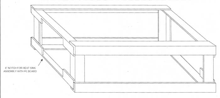
FIGURE 3: Chassis frame assembly.
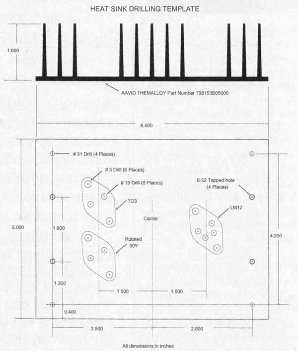
FIGURE 4: Heatsink drilling dimensions.
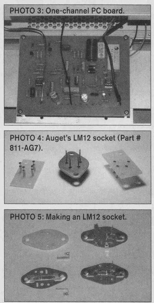
PHOTO 3: One-channel PCB;
PHOTO 4: Auget’s LM12 socket; PHOTO 5: Making a LM12 socket


POWER SUPPLY PARTS LIST
DERIVATION OF THE GAIN EQUATION AND CALCULATION OF RESISTOR VALUES
CHASSIS MATERIALS
AMPLIFIER PARTS LIST (PER CHANNEL)
My home theater system (Photo 6) is amplified by three of the cascoded LM12 stereo amps for the front, back, and sides, and a lower power LM12 stereo amp driving a pair of speakers for the center channel. The main speakers are Magneplaner MG-IIIas. Altec Lansing surrounds are for the sides and the rears are MG-Is. The surround processor is an Outlaw Audio Model 950 that doesn’t have phono in puts. Because I still love my vinyl, I built the “Pearl Phono Stage” preamp featured in the June 2002 issue of audioXpress .
MISCELLANEOUS PARTS
Connectors, binding posts, mounting hardware, and so on are left to the discretion of the builder.
Magnecraft makes a solid-state relay (part no. 70S2-04-C12-N) that can serve as a power switch and can be actuated from the trigger output of most surround sound processors. I’ve built one into a power distribution panel with power re lays and timers to sequence the turn on of the power amps in my home theater system. Turning on all amplifiers at the same time trips a 20A circuit breaker in my home breaker box.
============