Here are construction plans for a power supply that you can use to test preamplifier and small power amplifier circuits with vacuum tubes.
A regulated power supply is a very useful device for the home constructor. Using a benchtop sup ply, you can fire up novel tube projects and test the circuit before you invest in a dedicated (in-built) power supply. You can also use the regulated supply to provide existing amplifiers or receivers with a clean plate voltage. A regulator can improve the reproduction of sonic details because it suppresses hum, noise, and other forms of interference on the supply rail.
My wish list at the start of the PSU project looked like this:
1. Output voltage should be in the range of 240 to 300V (suitable for most DIY tube circuits).
2. The output current limit should be at least 100mA, to allow experiments with (small) power amplifiers.
3. The 300V supply should be a tube circuit (for nostalgia’s sake and for the sake of sturdiness).
4. In addition to the powerful 240 to 300V supply, a small regulator should provide a variable (negative) bias voltage.
5. A heater voltage supply should also be included. I decided to incorporate a 6.3V DC supply of maximally 5A.
6. Most electronic parts should come from the junk box.
HIGH-VOLTAGE REGULATOR
After examining some literature on voltage regulators and inspecting the inventory of my attic, I decided to build a circuit proposed by RCA as late as 1975 [2]. The schematic is shown in Fig. 1. This regulator, which can supply maximally 225mA at 250V, met goals 1 and 2.
RCA employed a 5651A tube (voltage reference), a 5751 dual triode (error amplifier), and a 6080 dual triode (series pass element). I did not have these tubes in my junkbox, but I found useful equivalents: a 85A2 from Mullard (new old stock), a 12AX7 from Sovtek (brand new), and a 6AS7G from RCA (new old stock). Appropriate ceramic sockets (one 7 miniature, one nova and one octal-type) were also present (leftovers from the Royal Dutch Navy).
Because I did not have an appropriate plate balancing potentiometer of 160 ohm (R1 in Fig. 1), I used a rheostat of 100-ohm and 10W and soldered two resistors of 33-ohm 5W at both ends of the wiper track, so the total resistance between the two plates of the 6080/6AS7G became 166 ohm.
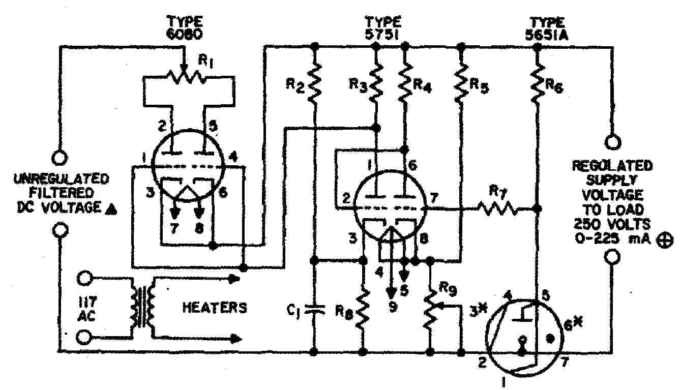
FIGURE 1: Schematic of the high-voltage regulator (as published in RCA Receiving
Tube Manual RC-30).
VOLTAGE DOUBLER CIRCUIT
RCA specifies that the unregulated DC at the input of the regulator should be 375V at zero load current and should not drop more than 50V at maximum load (225mA). I didn’t have a suitable transformer from the tube era, but I discovered a power transformer with many secondary voltages in my attic which I had salvaged from a damaged solid-state amplifier. The size of the transformer core suggested that it could supply at least 250W, and it included a secondary winding of 140V with a center tap (i.e., 70-0-70V). I combined this junkbox transformer with a voltage doubler circuit to generate the appropriate unregulated DC for the voltage regulator.
The schematic of my voltage doubler is shown in Fig. 2. The output voltage of a doubler drops more under load than the output of a bridge rectifier. However, with the hefty transformer and the big reservoir caps which I employed, the input voltage to the regulator is maintained within the margins specified by RCA. Other disadvantages of a doubler are: (1) there is more ripple on the raw DC than with a bridge rectifier, and (2) the ripple frequency is 50Hz (in the US , 60) rather than 100Hz (US, 120). This is the price you pay for using junkbox parts.
I included resistors R1 and R2 (Fig. 2) to limit the current surge through the rectifier diodes when the power supply is switched on. Right after switch-on, capacitors C1 and C2 haven’t been charged yet and they constitute virtually a short- circuit for diodes D1 and D2.
Resistors R3 and R4 are “bleeders” which ensure that the electrolytic capacitors C1 and C2 are rapidly discharged after power has been switched off. With out R3 and R4, C1 and C2 maintain an electric charge for several hours, threatening the lifespan of the unwary experimenter (a.k.a., yours truly).
OUTPUT VOLTAGE CONTROL POTENTIOMETER
After I had built the circuits shown in Figs. 1 and 2, my regulator worked nicely, but the output voltage tended to drift. I thought the 85A2 tube was to blame, but this turned out to be not the case. Potentiometer R9 (Fig. 1) was causing the problem. Power dissipation in this device depends on the setting of the wiper and can be as high as 1.3W. Most modern potentiometers can handle only 0.25W!
I had used an above-average-quality 10k pot made by Bourns, but even this could not handle more than 0.5W. The pot became blazingly hot, resulting in a rapid increase of its resistance. It was clear that it did not have the proper power rating. During the tube era, I had used wirewound potentiometers with a power handling capacity of several watts, but I did not have such items in my junkbox.
After some thinking, I came up with the following solution (Fig. 3): I replaced R9 with a ten-turn 1k potentiometer from the East German company RFT (military stock, power handling 2W) with 4k7 and 820 wirewound 5W resistors in series. A switch (S1) allows the selection of two voltage ranges: 235-260 and 260-290V. Within each range, P1 allows continuous adjustment of the out put voltage. After replacement of R9 by the circuit of Fig. 3, the HV regulator is quite stable.
My on-off switch has two poles and three positions. The first position is “off,” the second position is “standby.” In this position, mains power goes only to a 220:6.3V transformer which powers the heaters of the 12AX7 and the 6AS7G. After about 15 seconds, when the heaters have reached their operating temperature, the switch is set to the “on” position. Then, all circuits are receiving power (including the circuit of Fig. 2) and the supply becomes fully operational. The opposite procedure is followed during switch-off.
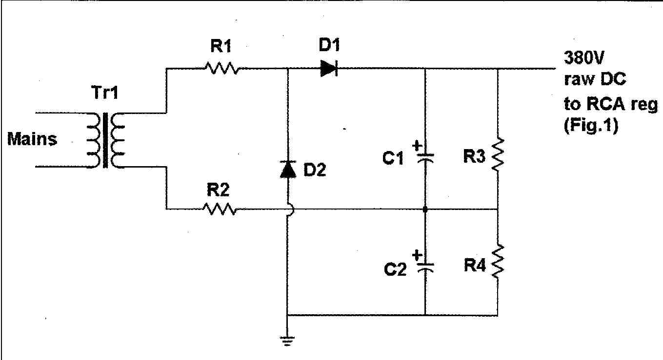
FIGURE 2: Voltage doubler generating raw DC for the RCA regulator (shown
in Fig. 1).
HEATER SUPPLY
My heater supply (not for the 12AX7 and 6A57G tubes in the HV regulator, but for powering the heaters of external circuits) is shown in Fig. 4. Initially, I had made a 6.3V DC supply based on an LT1084CP regulator and a Linear Technology application note. However, this circuit failed after the initial tests. Because the LT1084 I used was salvaged from a damaged piece of laboratory equipment, the IC probably was already broken before I (re)used it.
Unfortunately, I did not have another LT1084 in my junkbox, and our local electronics stores do not sell this component. Thus, I tried a 7806 with external pass transistor and current limiting circuit. Although that circuit (taken from the Linfinity application note worked well, it turned out that a rather high input voltage was required if the circuit was to deliver several amps at 6.3 V. The raw DC supplied by my 9V 50VA transformer with bridge rectifier and smoothing capacitor was too low (by 1 or 1.5V) for proper voltage regulation by the circuit based on the LM7806.
In a very old issue of Elektuur (known in the US as Elektor Electronics), I discovered a flexible circuit built from a small number of discrete components (Fig. 4)5. An input-output voltage difference of only 2V is required for proper operation of this regulator, and the circuit can sup ply currents up to 7A. Output voltage is identical to the zener voltage of D3 minus 0.5V. Zener voltages ranging from 4.7V to 48V are possible. The zener is fed from a current source (Q1, D1, D2, R1, R2). Q2 and Q3 are the error amplifier, and Q4 is the pass device.
Because I had all parts in stock and could build the circuit in a single evening, I decided to give this vintage regulator a try. It performs nicely. The output voltage drops only 90mV (from 6.29 to 6.20V) when the output current is in creased from 0 to 3A, indicating an internal resistance of approximately 30 m-ohm.
NEGATIVE BIAS SUPPLY
The regulator providing a variable negative bias voltage is even more conventional than the 6.3V heater supply. It is a standard application of the LM337T IC (see Fig. 5, taken from a SGS-Thomson application note).
My junkbox transformer powering the RCA voltage regulator has both a 70-0-70V secondary winding and a separate winding of 28V AC. With a bridge rectifier (B250 C5000) and 4700uF 80V smoothing capacitor, the latter winding generates a raw DC of -35V for the circuit of Fig. 5.
I added protection diodes D1 and D2 to ensure survival of IC1 when the regulator is feeding a capacitive load and mains power is switched on (or off). Capacitor C2 improves the suppression of mains-induced hum.
CABINET AND FINAL TESTING
Because of the size and mass of the components used in this power sup ply (three big transformers, several large smoothing caps, tall 6AS7G triode), I could not find an industrial cabinet large enough to hold all parts. Thus, I made a cabinet from plywood, MDF, and perforated aluminum (18mm thick MDF for the bottom, 6mm MDF for front and back, 16mm plywood for the cabinet sides, 1mm perforated aluminum for the cover). All parts are held together with screws and wood glue.
The circuit grounds of the three power supplies (high-voltage regulator, 6.3V heater regulator, negative bias voltage) are kept separate (not joined within the cabinet) to avoid ground loops when the supplies are used to feed an external tube circuit. Now you can connect the negative (or positive) ends of the heaters of the external circuit either directly to the B+ ground or to the B+ ground via a small capacitor, or keep them floating.
Because of the simplicity of the three regulator circuits, I did not use etched printed circuit boards. I glued narrow strips of single-sided, copper-clad PC board material on pieces of unetched PC board. I soldered the components between these insulated “islands,” and used the unetched PC board as a ground plane.
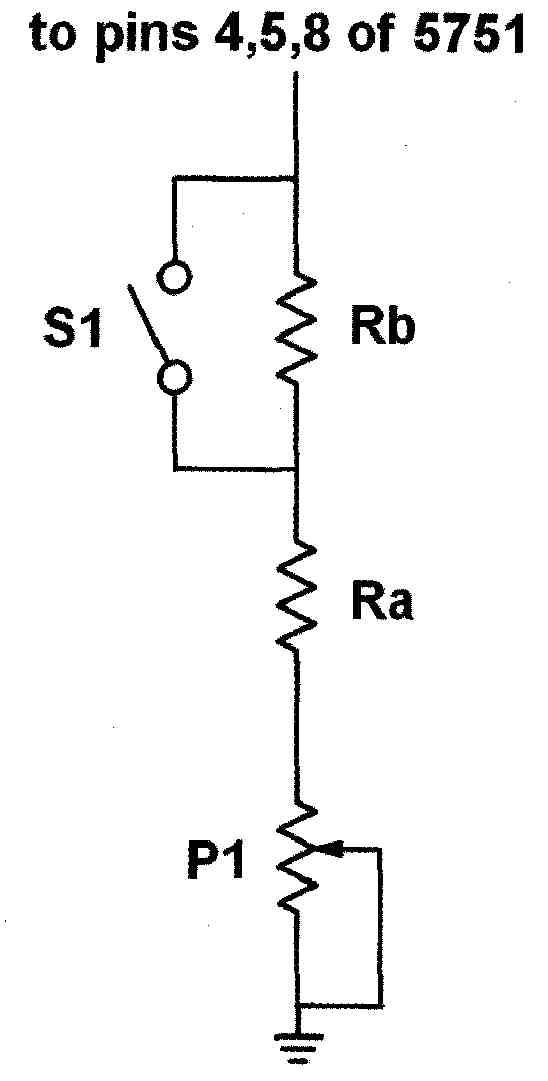
FIGURE 3: Voltage control circuit (replacing R9 in Fig. 1). P1 is a 1k-ohm
10-turn potentiometer, Ra is 4k7 5W, Rb is 820-ohm 5W. S1 selects the range
of output voltages (235-260 or 260-290V, respectively).
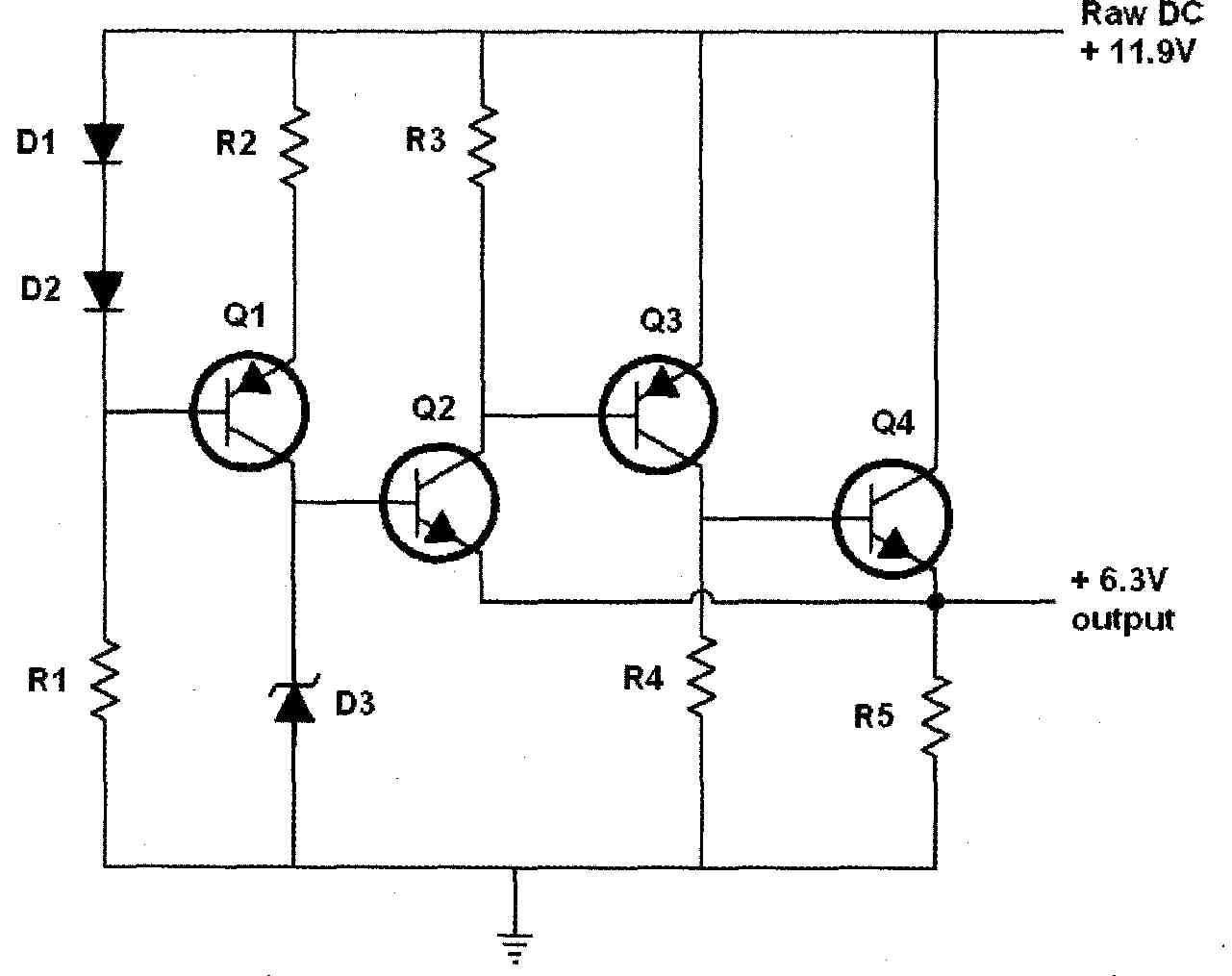
FIGURE 4: Heater supply. Originally published in Elektuur (Dutch version
of Elektor). Raw DC comes from a 220:9V, 50VA transformer, 250V 10A bridge
rectifier, and 22000pF 25V electrolytic.
I mounted meters for reading the B+ voltage and the negative bias voltage (300V and 35V full scale, respectively) at the front of the cabinet, to indicate proper operation of the power supply and disappearance of the output voltage after switch-off.
Tests showed that the high-voltage regulator can easily supply more than 100mA (I did not go further because I didn’t have a proper dummy load), the negative bias supply more than 500mA, and the heater supply more than 3A be fore any appreciable drop of the output voltage occurs.
Thus, I managed to build a flexible power supply for vacuum tube projects, completely from junkbox parts, which will, I hope, serve me well for a long time.
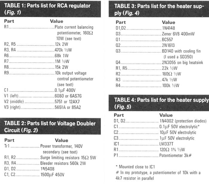
TABLE 1: Parts list for RCA regulator (Fig. 1)
TABLE 2: Parts list for Voltage Doubler Circuit (Fig. 2)
TABLE 3: Parts list for the heater supply. (Fig. 4)
TABLE 4: Parts list for the heater supply (Fig. 5)
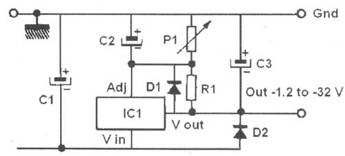
FIGURE 5: Negative bias supply (from SGS-Thomson application note for the
LM337T). Raw DC in (-35 V, from 28VAC xfmr, bridge rectifier, 4700uF capacitor)
REFERENCES
1. The classical treatment of this subject is F.V. Hunt and R.W. Hickman, “On Electronic voltage Stabilizers,” Review of Scientific Instruments, Vol. 10, 6-21, 1939. A recent article providing schematics with “modern” tubes is: Terry Bicknell, “Valve (Tube) Regulated Power Supplies,” May ‘08 audioXpress , p. 26. Another good introduction is “Vacuum-Tube Regulator Design” by Denzil Danner, Glass Audio 3/93, p. 16. Nice introductions can also be downloaded from the Internet, e.g., a five- part series on “Tube Voltage Regulators” by John Atwood, published in Tube CAD Journal (volumes 1 and 2, 1999-2000), and another five-part series by Steve Bench. Steve’s website is a highly recommended goldmine of tube lore.
2. RC-30 Receiving Tube Manual, Including Picture Tubes and Industrial Receiving Tubes, RCA Corporation, Camden N.J., 1975.
3. LT1083/LT1084/LT1085 7.5A/5A/3A. Low Dropout Positive Voltage Regulators, Linear Technology Corporation, Milpitas, Calif. 1994 (see figure TA04 in this document). NB: If you need datasheets or equivalents for any electronic component, try alldatasheet.com.
4. SG7800A/SG7800 Positive Fixed Voltage Regulator, Linfinity Microelectronics, Garden Grove , Calif. 1997 (see Fig. 7 in this document).
5. “Spanningsstabilisator met hoge konstant heid en lage RI,” Elektuur, July/August issue 1972.
6. LM137/LM237/LM337 Three-Terminal Adjustable Negative Voltage Regulators, SGS-Thomson Microelectronics, 1993 (see bottom figure on page 8 in this document).
============