A JEET input and ultra-low distortion AD797 op amps provide excellent full-spectrum noise figure, headroom, and RIAA precision. Sound quality is extremely natural, transparent, and dynamic.
Someone writing to Stereophile (or wast it TAS??) complained that vinyl can’t provide sonic fidelity, because this “primitive system uses physical contact.” Apparently this writer isn’t aware that vibrating strings, and so on, physically contact the air, which physically contacts your eardrums!
For those interested in obtaining the naturalness and resolution that LPs are capable of, this phono preamp provides excellent reproduction and resolution over a very wide dynamic range.
FEATURES:
1. 81dB “A” weighted SNR with typical MM, 75dB with MC, and 89dB with high-output (2.5mV) MC, re 5cm/sec.
2. Low noise over the fill spectrum, not just averaged.
3. 0.002% THD, mostly 2nd harmonic, full spectrum.
4. Instant MM/MC switching, no “tweaky” circuitry, no adjustments.
5. 7.2V RMS maximum output. Preamp dynamic range is 118dB (MM), 98dB (MC).
6. Typical headroom re 5cm/sec is 19dB at 1kHz, 36dB at 20kHz.
7. Passes the sonic “intrinsic fidelity” test (described later).
OVERVIEW
The three-stage design (see gain partitioning in Fig. 1) is configured to avoid noise degradation by circuitry following the input stage, particularly at high frequencies where the RIAA rolloff results in the lowest gain. Additional benefits are independence between MM/MC gain switching and the RIAA equalization, and lower distortion than a two-stage; this is because of the comfortably lower required closed—loop gains. If desired, you can easily change the MM and/or MC gains. As is, the 1khz gains are 43.8dB (MM) and 63.8dB (MC).
Note that the input stage provides only the 2122Hz (75us) rolloff portion of the RIAA de-emphasis. This minimizes the gain range (over frequency) required, allowing enough gain at 20kHz to maintain a good overall noise figure (NF).
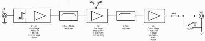
FIGURE 1: Block diagram; overall 1kHz gain = 43.8dB (MM), 63.8dB (MC).
Norm Thagard’ reports that Shure Labs found velocity peaks of 25cm/sec at 1kHz and 50cm/sec at higher frequencies. The input stage (and the entire preamp) can accommodate this, while the input gain (35.7dB at 1kHz) is high enough to amplify MC outputs (0.5mV at 5cm/sec typical) well above the noise level of the following circuitry. Thus, the MM/MC gain switching can be done in the second stage, allowing the all-important input stage to be optimized as a “fixed gain cell” of very high dynamic range. Overall, the preamp’s own dynamic range (apart from cartridge noise limitations) is 7.2V RMS (maximum output) divided by 9.13 RMS (“A” weighted output noise), which is 118dB, in MM mode (98dB in MC mode).
DETAILED CIRCUIT DESCRIPTION
The paralleled JFETs (Q1) are AC-coupled into the inverting input of U1, whose output is non-inverting with reference to the input signal. But the connection through R6, R7, C9 to the JFET source (and R3) is overall inverting, providing negative feedback (NFB). R5 gives U1 DC stability, while R4, C5, and C6 provide HF stability (the AD797 is capable of 110MHz oscillation, so you must closely ground C7 and C8). R5, C6 form a 10kHz pole, but the high loop gain through Q1 extends this to well above 100kHz. R6, R7, C9 form the 2122Hz RIAA rolloff (where the reactance of C9 equals R6 + R7 = 750 ohm. However, R7 (and the non-inverting configuration with R3) cause the -20dB/decade slope to flatten with a transmission zero at 35.6kHz, where Xcg = (R3//R6) + R7 = 44.7 ohm.
This flattening could be exactly compensated for by the R9/C11 rolloff be fore the second stage U2. However, I set this rolloff at 55.1kHz. The net result is that at 20kHz the response is +0.65dB with regard to the normal RIAA curve. I say “normal,” because, as Norm Thagard points out, record cutter heads use a 50kHz rolloff pole to protect the modern kilowatt liquid helium-cooled mechanics from RIAA pre-emphasized ultrasonic transients. (Who am I to argue with a record-setting astronaut?) This rolloff is -0.64 dB at 20kHz, hence the above (doubtfully audible) 0.65 dB boost. Close enough for vinyl record-setting!
2ND STAGE (U2)
C10 and R8 form a 3.0Hz high-pass rolloff, as does the C15/R13 combi nation at the output of U2. Together, they’re down 3dB at 4.7Hz, in addition to eliminating DC offset accumulation. U2 provides selectable gains (7.2dB for MM, 27.2dB for MC, at 1kHz) and has a flat response to audio; it’s -3dB at 2MHz in MC mode, from C12, which ensures HF stability.
OUTPUT STAGE (U3)
R14 is needed to stop a 40MHz oscillation involving U2 and/or U3. The output stage gain at 1kHz is 0.9dB. R16 and C16 provide the 50Hz (3180us RIAA rolloff pole. The non-inverting configuration produces the required slope flattening, with the transmission zero at 500Hz. This is (within 0.1dB) where X equals R15//R16.
I added R19 and C20 as a “last minute tweak” to optimize the RIAA accuracy. C19 removes any DC offset. With an (unlikely) low load at 4k7, 20Hz response will drop only 1dB. R18 sets the output impedance to 200-ohm. S2 mutes the outputs if desired. You should activate it before applying power to the pre amp if the audio system is on, to avoid huge turn-on transients.
CAPACITORS
Some people claim they don’t like “capacitor sound.” But a phono preamp needs them, unless you use inductors.
The film caps specified here are inexpensive, but of very high quality; I doubt that they have any “sound.” With the largest film cap (C19, 3.3 I measured an ESL of only 14 nano-henries (about that of a 1” wire) and an ESR at 750kHz of only 0.021 ohm.
You should realize that as the music waveform travels to the record grooves, the signal “train” passes through many “stations” named “Capacitor Junction”— inside mike preamps, mixing consoles, cutter head amps, and so on. In fact, the best mikes are capacitors—no one complains about “capacitor sound” there! But, of course, as with other components, high quality is important.
Q1
The original low-noise Toshiba 2sk389 went out of production in the early 2000s.
The LSK389 is advertised in as a “nV (per √Hz) Low Noise Dual JFET,” by Linear Integrated Systems, (510) 490-9160 or (800) 359-4023. The datasheet (linearsystems.com) specifies 0.9nV √Hz typical, 1.9 maximum at 1kHz, 2mA, 10V.
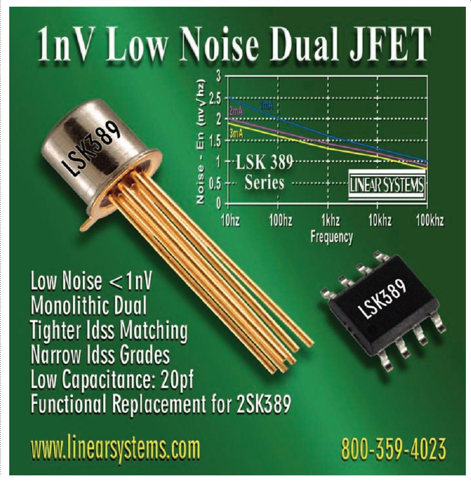
I measured six samples; four had noise less than 1nV/ √Hz, but the other two were 2.18 and 2.83 nV √Hz. All had an IDSS within the 6-12mA spec for the “B” category (LSK389B TO-71 used here).
However, considering the advertised 1nV/ noise, you should request units meeting this number. The price as of last fall was $7.29 (1-99) and $5.87 (100-999).
HEADROOM
The input stage can handle 92mV RMS 1kHz input and 510mV RMS at 20kHz. However, due to the following stages’ gain of 8.1dB at 1kHz (U2 and U3 combined), maximum preamp inputs are 45mV RMS (64mV peak) at 1kHz, and 330mV RMS (467mV peak) at 20kHz. Relative to the 25cm/sec (1kHz) and 50cm/sec (HF) peak velocities reported this is a headroom of 8.1dB (1kHz) and 19.4dB (20kHz), with a 5mV/5cm/sec MM cartridge. Relative to the “standard” 5cm/sec velocity (RMS), the headroom is 19.1dB (1kHz) and 36.4dB (20kHz).
IMPROVING HEADROOM
For higher output cartridges, or for any reason, you can increase the 1kHz maximum input to 92mV RMS (130mV peak) by reducing the second stage (U2) gain from 7.2dB to 0dB. To do this, simply delete R11 in Fig. 2. (This will decrease the MC gain by only 0.5dB.) The maximum input at 20kHz (MM) will then be 510mV RMS (721mV peak). Doing this results in an overall preamp MM gain at 1kHz of 36.7dB. Output with 5mV RMS input is then 342mV RMS.
With a 5cm/sec 5mV rated Shure cartridge and the loudest part of a “hot” LP (described in the “Showtime” section at the end of this article), the highest peaks were 2.9V at the preamp output. This is about 10dB below clipping. With very low output MC cartridges, you can obtain state-of-the-art low noise with Paul H. Rossiter’s head amp driving the LP797 set for MM gain.
POWER SUPPLY
Not wanting a separate power supply box, nor the induced hum of an internal line transformer, I took advantage of a readily available 24V DC “wall wart.” An additional benefit is UL and/or other safety approvals.
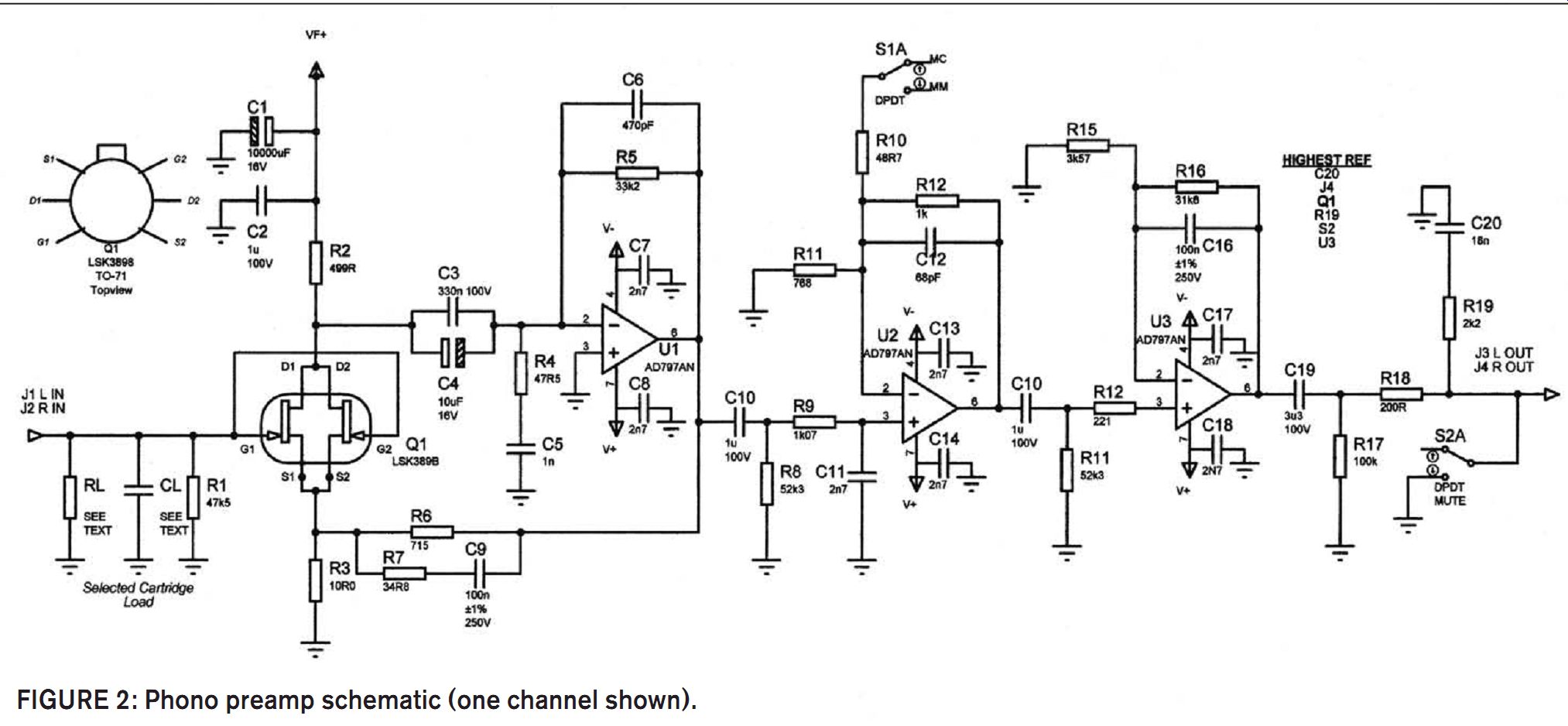
FIGURE 2: Phono preamp schematic (one channel shown). Note: "RL" at input is
not clearly stated by author. It may be to further trim input load resistance
"R1".
The opamps, with their 130dB power supply rejection ratio (PSRR), couldn’t care less what kind of DC you feed them, provided that their HF bypass caps (C7, 8, 13, 14, 17, 18 in Fig. 2) are closely grounded. So the simple RC ripple filtering of (Fig. 3) R1, C1, R3, R4, C2, C3 provides low enough 120Hz ripple (0.2mV RMS) such that the op amps attenuate it to 63 pica volts. They’re fed the V and V voltages.
Not so with the single-ended JFET input! This needs extreme hum rejection. Also, conventional regulators have far too much noise. And while the FET bias doesn’t need to be regulated to some precise value (the feedback structure stabilizes the gain), the bias must not be subject to AC line voltage fluctuations.
The circuitry with Q1 and D3 provides excellent rejection of line fluctuations and ripple. However, I observed some LF noise from the D3 zener adding to the preamp’s noise floor, from about 5-40Hz. This was fixed by the filtering of R7 and the 10,000uF cap (C1 in Fig. 2), forming a 0.8Hz low-pass rolloff.
Note the role of D2 (Fig. 3), which clamps the V- to -12V, leaving +12V for V+ and the Q1 circuit. I couldn’t have two zeners across the full DC input (about 26V, more on this later) — as this input varied, the two zeners would shut off and/or draw large currents. But two are not needed, because the op amp supplies don’t need regulators, and the JFET supply has it.
Here’s how D2 functions: As shown in Fig. 3, the total positive supply current is 76mA, which is drawn from the TI wall wart. Being a single (not bipolar) supply, TI must then draw this same 76mA from its negative terminal. But the negative supply output (V) and the LED’s 2mA provide only 52mA. The difference, 24mA (the Q1 circuit’s current), is pulled through D2, which is thus happily kept on. Looks strange, but works well.
A NOTE ON TI
The specified unit is rated at 24V, 400mA, but only 76mA is used. This overrating has three benefits:
1. TI runs very cool.
2. The larger unit has a large internal filter cap, about 1000uF.
3. The output voltage is higher, about 26V.
R1 (Fig. 3) will act as a fuse if there’s a short or reverse voltage applied.
ALTERNATE POWER SUPPLY
If desired, you can use a regulated ±15V DC supply, which you must isolate from the AC line ground, but connect its common ±15V point to the preamp chassis ground. Referring to Fig. 3:
1. Remove (or do not install) D2, C1, R1, and J5. You can in stall normally grounded jacks for the ±15V supply.
2. Connect the +15V to the left side of P3, and the -15V to the left side of R4.
With this ±15V supply and the “stock” U2 gain of Fig. 2, the preamp’s maximum input and output levels will increase by about 3dB.
With the specified “wall wart,” MC output hum is only 21uV RMS. “A” weighted, that’s 108dB below the signal with 0.5mV input. With MM gain the figure is 128dB.
CONSTRUCTION
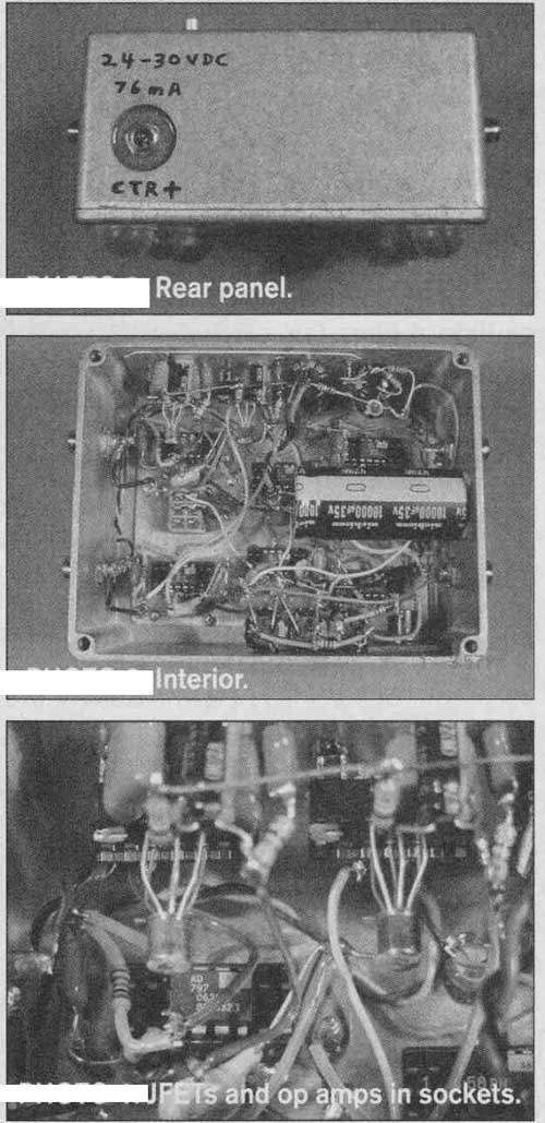
I built the preamp in a Hammond aluminum box (1590C, Digi-Key HM153, 4.72” x 3.70” x 2.07”). Note that J5, the DC input jack, must be insulated from the box. I made a ¾” hole in the back panel (Photo 2), using a Greenlee chassis punch, P/N 730BB-3/4. Then I glued a 1” square piece of 1/8” plywood, with a 5/16” centered hole for J5, to the inside of the box panel. Later, I found an insulated jack, Mouser 163-4303EX.
As usual, I should have used a larger box! The circuitry (Photos 3 and 4) is crammed onto two unetched cop per ground-plane boards, and the power supply components are glued to the sidewalls.
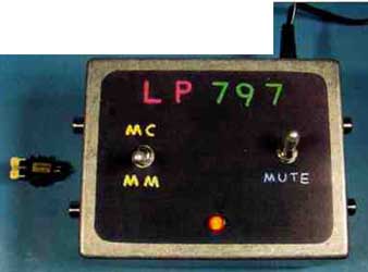
The specified switches have a nice feature: By lifting and rotating the handle, you can align the tabs to lock the switch position selected in place. You wouldn’t want S1 inadvertently thrown to “MC” with an MM cartridge, producing a +20dB blast! The switches provide excellent chassis grounding of the board. You should connect the ground end of R3 (Fig. 2) to a ground lug on the input jack.
I recommend using a larger box, the Hammond 1590D, Digi-Key HM154. Dimensions are 7.38” x 4.70” x 2.05”. If you’d like a nice deep purple pilot light, use the LED 5-UV-405-30 from Bivar (949) 951-8808, and change R2 (Fig. 3) to 3k3.
MM LOADING CAPACITANCE
I recommend reading Raymond A. Futrell’s “The LP Terminator,” on how to obtain the flattest frequency response given the high inductance of MM cartridges. The LP797 preamp input capacitance (without CL in Fig. 2) is only 21pF, because the Q1 drains see the “virtual ground” of U1 (no Miller effect), and also because of the “bootstrapping” of NFB to the Q1 sources. Mr. Futrell shows how the right phono cables can provide optimum capacitance.
RIAA ACCURACY
Figure 4 shows the deviations. As discussed, I incorporated compensation for the 50kHz cutter head rolloff (which causes a doubtfully audible 20kHz preamp gain increase of 0.64dB). The 0.36dB rolloff at 20Hz is intentional, because it’s due to the interstage infrasonic filtering/DC blocking. From 100Hz to 20kHz, the response variations of both channels fit within a ±0.07dB window. Channel balance tracks within 0.03dB across the band, and the two channels’ gains at 1kHz are balanced within 0.01dB.
This might have something to do with the fact that I hand-matched all resistors and caps in the signal path to within ±0.1% between channels.
NOISE PERCEPTION
My article “A Low Noise Measurement Preamp” covers the perceived effect on noise level and spectrum, due to per-octave versus per-Hz analysis, “A” weighting, and the RIAA curve. At the (you hope) low noise levels of audio components, “A” weighting is appropriate. Also, our hearing (at any level) analyzes spectral distribution on a logarithmic (per octave or fraction thereof) basis, not on the constant bandwidth (BW, per Hz) basis used in many spectrum analyzers.
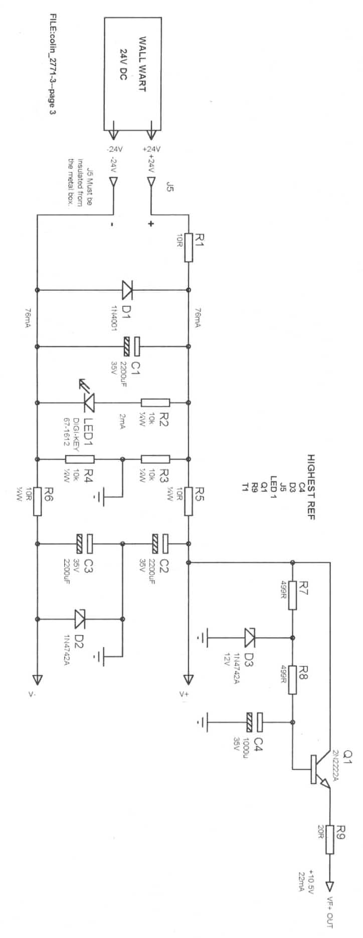
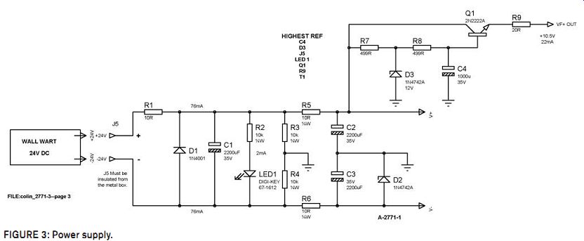
FIGURE 3: Power supply.
Figure 5 shows the preamp’s output noise spectrum (MM mode, input grounded) two ways: noise per 1Hz BW (lower curve 1) and noise per octave (upper curve 2). The upper curve is higher because audio band octaves have bandwidths much greater than 1Hz. But the total integrated noise (20Hz - 20kHz) is the same; noise power is noise power no matter how it’s (accurately) measured.
Because the JFET’s input spectrum is fairly flat on a per- Hz basis (white noise), curve 1 reflects the RIAA response, plus the JFET’s gradual LF noise increase (the LSK389 data shows 0.9nV/√ Hz at 1kHz, 2.5 at 10Hz, typical).
“A” WEIGHTING
The lower curve in Fig. 6 (curve 1) shows this same preamp output noise (MM mode; MC is 20dB higher) with “A” weighting. Notice how the “A” curve’s strong LF rolloff, plus the RIAA response’s strong HF downslope, result in a broad peak around 1.5kHz. Thus, the perceived noise, if heard at all, is “mellow” sounding, not “hissy” like white noise.
This is why I selected the preamp’s topology and ultra- low noise op amps in all stages. Because the RIAA curve is -19.62dB at 20kHz relative to 1kHz (-18.98dB if the 50kHz cutter head compensation is included), circuitry following the input stage could add HF noise. For example, a preamp design with only 20dB 1kHz gain in an MM input stage would, after RIAA EQ have almost no gain at 20kHz. This means that the following stages, even if they have as low a noise level as the input stage, would add 3dB to the input-referred preamp noise at 20kHz.
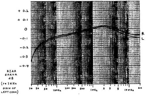
FIGURE 4: RIAA accuracy.
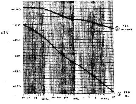
FIGURE 5: Noise out, MM, input grounded. Total 20Hz — 20kHz noise (unweighted)
= 26.0uV RMS (-91.7dBV) (MC = 20dB higher).
So it’s apparent that SNR alone doesn’t tell the whole story; it’s the “A’ weighted and per-octave analyzed spectrum that does. My article shows that SNR values based on a preamp’s un weighted and nearly white input noise are improved by about 6.8dB.
NOISE WITH AN MM CARTRIDGE
I measured the impedance of a (Realistic) Shure R27E cartridge (same as Shure M75). Although old and inexpensive ($40.00 Radio Shack catalog, 1977-1979), its impedance is typical: 635 ohm + 631mH. Paralleled with this preamp’s 47k3 load, the impedance seen by the preamp at 1kHz is 943 ohm (resistive) + 33k84 (inductive); impedance magnitude is 3k95. But at 10kHz, z = 19k5 + j23k; magnitude is 30k2.
The upper curve (2) in Fig. 6 shows “A" weighted, per-octave preamp output noise with this cartridge. The increase in HF noise with regard to the lower curve (1) is almost entirely due to the 47k5 (R1) loaded cartridge’s resistive thermal noise. The preamp noise degradation (NF) is only 0.3dB maximum across the band. The curve broadly peaks around 4kHz, so if heard at all, still doesn’t sound “hissy.”
MM PREAMPS WITH BIPOLAR TRANSISTORS
I had first tried an AD797 op amp alone (no JFET) at the input. With a low source impedance such as an MC cartridge provides, all was fine. But with the MM cartridge, the noise was about 8dB higher than with the JFET input; plus (rather, a negative) the noise peaked around 10kHz. Too much and hissy! The reason is the bipolar op amp’s input current noise. Now, 2pA/_/Hz might not sound like much, but when multiplied by the loaded cartridge’s 30k impedance magnitude at 10kHz, a noise voltage term of 60nV_/Hz undesirably appears!
This is 10.5dB higher (at 10kHz) than the 18nV/_/Hz noise of the loaded cartridge’s 19k5 resistive component:
Combined, the resulting NF is 10.8dB at 10kHz. The JFET reduced the NF to 0.3dB.
THE BOTTOM (NOISE) LINE
Figure 7 tells the whole perceived noise story. The vertical dB scale is “A” weighted per-octave analyzed output noise (as we perceive low-level sounds), relative to the 5cm/sec outputs of three cartridges driving the LP797 preamp. The total 20Hz - 20kHz SNR values are stated. Some notes:
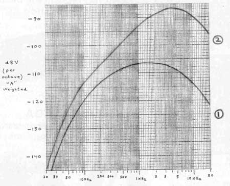
FIGURE 6: Noise out, MM, “A” weighted, per octave analysis. 1 = input grounded,
as in Fig. 5; total noise 20Hz - 20kHz = 9.13uV RMS (-100.8dBV). 2 = with
Shure R27E cartridge; total noise 20Hz — 20kHz = 71.9 RMS (-82.9dBV) (z =
635-ohm + 631mH).
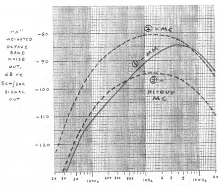
FIGURE 7: Noise out with cartridges. 1. MM 635ohm + 631 mH, 5mV. Total SNR
= 80.8dB, preamp mode MM. 2. MC, 50 ohm, 0.5mV. Total SNR = 75.2dB, preamp
mode MC. 3. hi-out MC, 50-ohm, 2.5mV. Total SNR = 89.2dB, preamp mode MM.
1. Above 7kHz, the typical 0.5mV MC cartridge has slightly better SNR (lower noise with reference to signal) than the MM cartridge, even though the total (full band integrated) SNR is 5.6dB better with the MM. This is froth the HF noise increase, due to the high MM inductance not effectively shunting the 47k5 load’s thermal noise, as I described.
2. Notice that the high-output MC cartridge has the best SNR of all: 89.2dB. The example used is the Dynavector 10 x 5, available for $380 from Music Direct. Art Dudley of Stereophile said, “wildly, highly recommended.” Its use of neodymium magnets generates 2.5mV at 5cm/sec; thus it uses the MM mode of this preamp, where the output is then 392mV RMS at 5cm/sec, and 1.95V peak at the 25cm/sec 1kHz peaks reported by Shure Labs. Peak dynamic range would then be 103.2dB, higher than that of any CD, and, of course, pure analog!
Tables 1 and 2 are the parts list. Table 3 shows measured performance.
COMPARISON WITH A $3000 PREAMP
Table 4 compares performance data between the LP797 and the Sutherland “Ph.D,” reviewed and measured by Stereophile (May 2005). For $3000 you get 8 to 20dB more noise, four times the THD, 28dB less 20kHz headroom, three times the RIAA error, and switching pop-producing DC output offset! (It also needs batteries.)
Review comments include “slightly soft bass ... lack of dynamic punch….dulling of piano ... guitar lacked impact, muted and a little pale.. .“The last words in the review were (no surprise) “Highly recommended.”
As I mention in the last section (“Showtime”), I compared guitars on LP (with the LP797) to a live guitar I heard the same day. The only “muting” I heard was when I flipped the “mute” switch! And my hearing is very good and well experienced.
REGARDING THE AD797
In response to a letter from David Elderton, Gary Galo refers to the AD797 as a “stellar performer,” but ruled it out for phono preamp inputs because of its need for a fairly low source impedance. He said it “would otherwise be a first choice for phono preamps.”
As I mentioned, high source impedances are affected by the AD797’s current noise. Hence the JFET input in this preamp. Thus, the noise figure is excel lent over a wide range of source impedances, and the AD797s are happy.
Then their stellar performance shines. It’s probably one of the most sonically transparent audio amplifying devices available, and its performance electrically agrees, including 0.0002% THD, 110MHz GBW, 20V/uS slew rate, and 130dB PSRR. The LSK389B/AD797 input stage cascade is completely stable, both HF-wise and regarding RIAA precision.
INVERSE RIAA NETWORK (IRN) TESTS
I built an accurate (±0.03dB) IRN to facilitate future measurements, confirm my direct RIAA test, and also to be able to view waveforms. Figure 8 shows a 1kHz linear triangle wave (left) fed to the IRN. The center response shows the IRN’s output; this is what would drive the cutter head. The recording pre-emphasis is evident.
This was fed to the preamp. The right shows the preamp’s excellent reproduction of the triangle wave. Figures 9 and 10 show 1kHz and 10kHz square wave responses.
INTRINSIC FIDELITY TEST
Having built a pair of IRNs, I thought about trying what can be called an intrinsic fidelity test Driving a phono preamp from an IRN feeds the preamp the same pre-emphasized response used in record cutters. So I fed this combination high-quality SACD music. This can be more stressful than LP outputs, because the SACD format (DSD) has a BW of 100kHz, and in this test any ultrasonic components are strongly amplified by the recording (inverse) RIAA response. The SACDs I used have peak player outputs of about ±3V.
I used an A/B switch, feeding a high- quality headphone amp and the excel lent Sennheiser HD 650 phones, to compare the direct SACD output with that from the LP797 preamp. The two signals were level-matched to within 0.02dB at 1kHz. 1 listened with much A/B switching, ranging from hearing an entire piece between switching, to just listening to the first two seconds, switching, restarting the track, and repeating the sequence 20 times. With a wide variety of excellent recordings, all direct to DSD, I listened as above, plus frequently switched rapidly in the middle of a sustained violin ensemble harmony, piano chord, sung note, and so on.
My hearing is very good; Ed Dell and Joe D’Appolito have praised my ability to hear fine details in my many speaker reviews. My sensitivity thresh old is within 3dB of the standard “good hearing for young people” audiogram. My HF limit is 14kHz, but there’s little spectral content in that top half-octave in natural music.
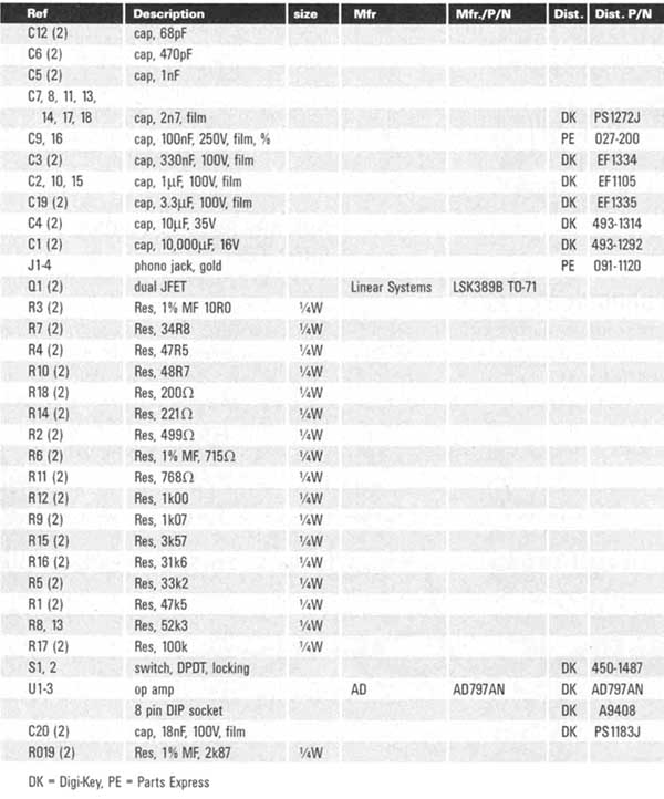
TABLE 1
========
TABLE 1
Ref Description size Mfr Mfr./P/N Dist. Dist. P/N
C12 (2) cap, 68pF
C6 (2) cap, 470pF
C5 (2) cap, 1nF
C7, 8, 11, 13,
14, 17, 18 cap, 2n7, film DK PS1272J
C9, 16 cap, 100nF, 250V, film, % PE 027-200
C3 (2) cap, 330nF, 100V, film DK EF1334
C2, 10, 15 cap, 1µF, 100V, film DK EF1105
C19 (2) cap, 3.3µF, 100V, film DK EF1335
C4 (2) cap, 10µF, 35V DK 493-1314
C1 (2) cap, 10,000µF, 16V DK 493-1292
J1-4 phono jack, gold PE 091-1120
Q1 (2) dual JFET Linear Systems LSK389B TO-71 [subsitute: OP249; jfe2140dr]
R3 (2) Res, 1% MF 10R0 ¼W
R7 (2) Res, 34R8 ¼W
R4 (2) Res, 47R5 ¼W
R10 (2) Res, 48R7 ¼W
R18 (2) Res, 200Ω ¼W
R14 (2) Res, 221Ω ¼W
R2 (2) Res, 499Ω ¼W
R6 (2) Res, 1% MF, 715Ω ¼W
R11 (2) Res, 768Ω ¼W
R12 (2) Res, 1k00 ¼W
R9 (2) Res, 1k07 ¼W
R15 (2) Res, 3k57 ¼W
R16 (2) Res, 31k6 ¼W
R5 (2) Res, 33k2 ¼W
R1 (2) Res, 47k5 ¼W
R8, 13 Res, 52k3 ¼W
R17 (2) Res, 100k ¼W
S1, 2 switch, DPDT, locking DK 450-1487
U1-3 op amp AD AD797AN DK AD797AN [subsitute: LT1028]]
8 pin DIP socket DK A9408
C20 (2) cap, 18nF, 100V, film DK PS1183J
R019 (2) Res, 1% MF, 2k87 ¼W
DK = Digi-Key, PE = Parts Express
========
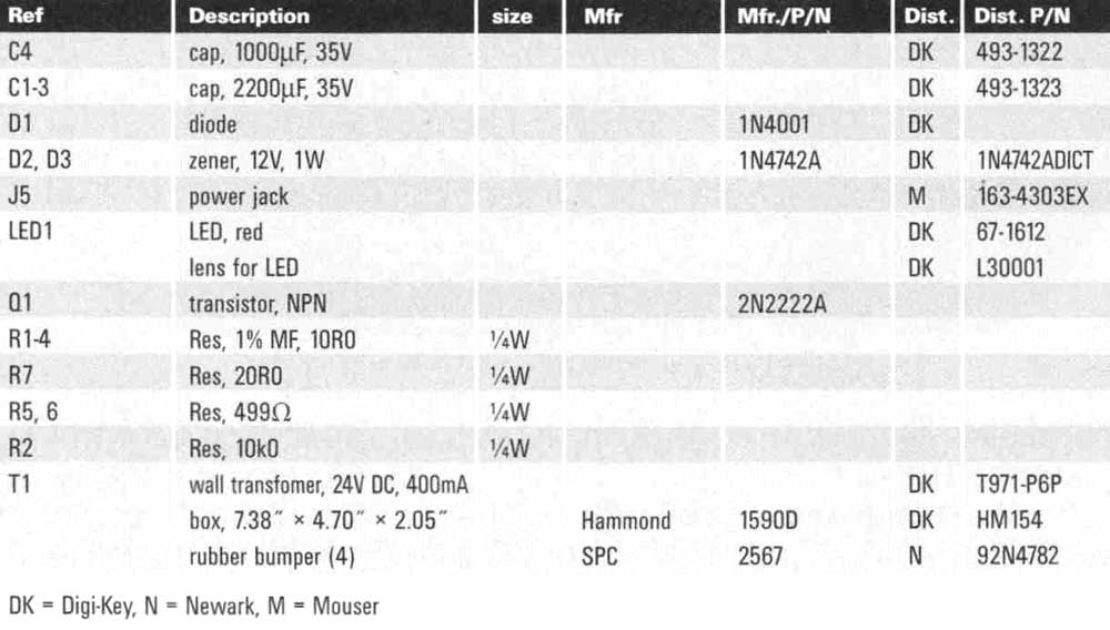
TABLE 2
========
TABLE 2
Ref Description size Mfr Mfr./P/N Dist. Dist. P/N
C4 cap, 1000µF, 35V DK 493-1322
C1-3 cap, 2200µF, 35V DK 493-1323
D1 diode 1N4001 DK
D2, D3 zener, 12V, 1W 1N4742A DK 1N4742ADICT
J5 power jack M 163-4303EX
LED1 LED, red DK 67-1612
lens for LED DK L30001
Q1 transistor, NPN 2N2222A
R1-4 Res, 1% MF, 10R0 ¼W
R7 Res, 20R0 ¼W
R5, 6 Res, 499Ω ¼W
R2 Res, 10k0 ¼W
T1 wall transfomer, 24V DC, 400mA DK T971-P6P
box, 7.38˝ × 4.70˝ × 2.05˝ Hammond 1590D DK HM154
rubber bumper (4) SPC 2567 N 92N4782
DK = Digi-Key, N = Newark, M = Mouser
========
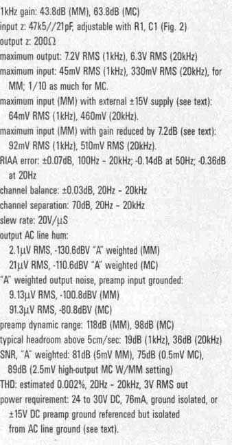
TABLE 3 Measured Performance
========
TABLE 3---Measured Performance
1kHz gain: 43.8dB (MM), 63.8dB (MC)
input z: 47k5//21pF, adjustable with RL, CL (Fig. 2)
output z: 200Ω
maximum output: 7.2V RMS (1kHz), 6.3V RMS (20kHz)
maximum input: 45mV RMS (1kHz), 330mV RMS (20kHz), for
MM; 1/10 as much for MC.
maximum input (MM) with external ±15V supply (see text): 64mV RMS (1kHz),
460mV (20kHz).
maximum input (MM) with gain reduced by 7.2dB (see text):
92mV RMS (1kHz), 510mV RMS (20kHz).
RIAA error: ±0.07dB, 100Hz – 20kHz; -0.14dB at 50Hz; -0.36dB at 20Hz
channel balance: ±0.03dB, 20Hz – 20kHz
channel separation: 70dB, 20Hz – 20kHz
slew rate: 20V/µS
output AC line hum:
2.1µV RMS, -130.6dBV “A” weighted (MM)
21µV RMS, -110.6dBV “A” weighted (MC)
“A” weighted output noise, preamp input grounded:
9.13µV RMS, -100.8dBV (MM)
91.3µV RMS, -80.8dBV (MC)
preamp dynamic range: 118dB (MM), 98dB (MC)
typical headroom above 5cm/sec: 19dB (1kHz), 36dB (20kHz)
SNR, “A” weighted: 81dB (5mV MM), 75dB (0.5mV MC),
89dB (2.5mV high-output MC W/MM setting)
THD: estimated 0.002%, 20Hz – 20kHz, 3V RMS out
power requirement: 24 to 30V DC, 76mA, ground isolated, or
±15V DC preamp ground referenced but isolated
from AC line ground (see text).
========
Well, try as I did (and I wanted to be the first to know about any deficiency), I heard absolutely no difference between the direct SACD output and that through the inverse RIAA/LP797 phono preamp. The HD650 phones are extremely resolving, such that I could hear the very slight inferiority of the SACD medium compared to vinyl (it’s much better than 16/44 CDs, though). But the LP797 output was indistinguishable from the direct SACD. No audible distortion, coloration, noise, hum, nor loss of resolution, tonality, spaciousness, instrument focus, transient precision, or dynamics.
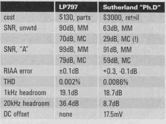 TABLE 4 comparison with a $3000 commercial preamp
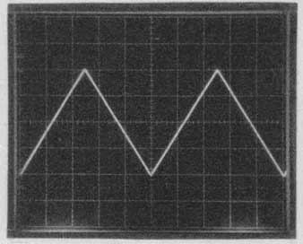
FIGURE 8: 1kHz triangle wave responses.
a: 1kHz linear triangle, input to in verse RIAA network, 1V/div
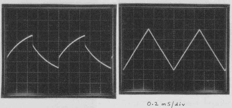
b: inverse RIAA output (signal FED to record cutter), to phono preamp input,
8mV/div.; c: phono preamp output 1V/div
I tend to conclude from this that the poor sound from some preamps (that measure well), as well as the claimed audibility of (good) resistors, caps, and cables, are due to circuit design problems (overly sensitive to component parasitics, shifting bias points, power supply inter actions, potential feedback loop instabilities, and so on). Another possibility is the lack of rigorously controlled testing with precise level-matching and rapid switching ability.
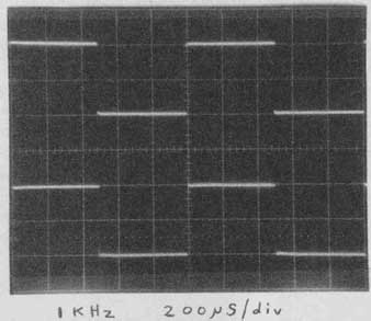
FIGURE 9: 1kHz square wave response. Input to in verse RIAA network (IRN)
1V/div; preamp out 1V/div
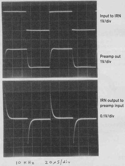
FIGURE 10: 10kHz square wave response.
LISTENING EVALUATION
I recommend the audiophile-quality LPs from Music Direct and Acoustic Sounds, because most popular music, and even some classical recordings, have been “produced” with EQ compression, synthetic reverb, and so on. This is be cause of the infamous “loudness wars,” boosting frequency ranges to make everything “stand out,” and so on. Just ask any mastering engineer.
Only with the best, honestly recorded LPs (and, of course, excellent speakers, power amps, and so on) can a phono preamp be correctly evaluated!
SHOWTIME
I connected the preamp between a vintage Shure 600-ohm MM cartridge (in an equally vintage Elac/Miracord turntable) and a 100W per channel solid-state amp, driving the “Venue” speakers, or Sennheiser HD650 phones. My best LP is “Blues, Ballads, and Jumpin’ Jazz” with Lonnie Johnson and Elmer Snowden, Analogue Productions APR 3001. Their “Revival Series” used the Wilson Audio Custom Tube mastering facility (acquired by Acoustic Sounds and RTI). As clear as it gets, guitars, bass, and voices. As a local radio station says, “no artificial ingredients, no preservatives, no pesticides!”
Meanwhile, earlier today I had the pleasure of hearing Tristan Light, guitar teacher/builder/player extraordinaire at Greenlaw’s Music, Laconia, N.H., play a beautiful Ibanez guitar. I heard it both acoustically and electrically through the HD650 phones. Full, rich, natural live string tone right in your face!
Well, the (admittedly different) guitars on the LP, heard on the same phones, sounded real enough that I would have had to instantly A/B the sound with the live guitar to notice any record/playback imperfections. The recorded acoustic bass was equally fall, clear, and natural. And the voices were close enough to live to not notice or care about the difference.
Even with the vintage cartridge, the sound (on the best LPs) had that live “fullness” or “roundness” of tone-coherent integrity of power down to the smallest tonal details. Even SACDs slightly degrade this, while standard CDs make the sound somewhat hollow, flat, and lightly “sandpapered.” But you know this; otherwise, you wouldn’t be reading about phono preamps—vinyl is king!
Excuse me now; I’ve got to see a man about a Dynavector...
This preamp design is the copyright-protected intellectual property of this article’s author. Commercial use including sale is prohibited. It is published here for the personal use of those respectful of the work of others.
REFERENCES
1. Norm Thagard, “A Phono Preamp for the (SA)CD Age, Part 1,” audioXpress magazine Nov. ‘05.
2. Raymond A. Futrell, “The LP Terminator,” audioXpress magazine Jan. ‘03.
3. Paul H. Rossiter, “A Head Amp for Very Low Impedance MC Cartridges,” audioXpress magazine Sep.’06.
4. Dennis C., “A Low-Noise Measurement Preamp,” audioXpress magazine April ‘07.
5. Gary Galo, response to letter from David Elderton, audioXpress magazine Aug. ‘05.
6. Dennis C.,"Sonic Comparison of Power Amp Output vs. Input,” audioXpress magazine Dec. ‘04.
============
CORRECTIONS [from AX, Oct 2007]
In my article “The LP797 Ultra-Low Distortion Phono Preamp,” aX Sept. ’07,
there are three errors:
1. Schematic, Fig. 2, p. 8: The MM/
MC switch S1A (left channel shown)
should have the top terminal (labeled
MC) grounded.
2. Also on Fig. 2: R19 should be 2k87,
not 2k2.
3. Power Supply Schematic, Fig. 3, p. 10:
The labeling on the wall-wart output
and J5 says “+24V” and “-24V.” This
would be 48V applied, which would
fry the entire preamp! The labeling
should be simply “24V,” with + and
– polarity markings.
I apologize for any problems these errors
might have caused.
--Dennis P. Colin
Also see: