|
|
By now, interested DIYers will have had a chance to digest remakes of Adcom’s GPP-565 preamp. Here are some additional refinements for the GFP-565 Preamp mod project.
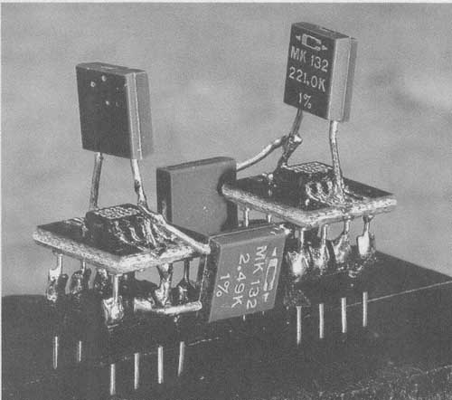
PHOTO 1: Two views of the AD825AR op-amp modules using Caddock MK132 resistors.
The SOIC chips must be soldered to an Aries DIP adapter. Otherwise, construction
is similar to Photo 28 in Part 3 of the original series.
Previously, I mentioned the possibility of using Analog Devices AD825AR op amp in the line stage, in place of the AD744KN. After working with the AD825 for some time, I find it to be a worthwhile improvement over the AD744, particularly in the area of inner detail and clarity. By comparison, the AD744 puts a slight veil over the sonic picture, though I would never have described the AD744 in such terms without a direct comparison to the AD825.
The AD825 isn’t avail able in a DIP package, only SOIC. The “AR” version is eight-pin, so you can use the same Aries adapter that I recommended in Part 2 of the series (Photo 1). Note that the output and local feedback for the AD825AR must be taken from pin 6.
• Solder the AD825AR to an eight-pin SOIC-to-DIP adapter, just as you did during construction of the regulators in Part 2. Note that pin 1 is on the side with the beveled edge. You can download a datasheet for the AD825 from analog.com for further clarification.
• Cut off pin 2 of the SOIC-to-DIP adapter.
• Solder the SOIC-to-DIP adapter to a Tyco eight-pin plug adapter, except for pin 2. You can also use the Aries 8-pin DIP header in the parts list (Table 1), but I prefer the gold-plated tyco because it’s easier to solder.
• Solder R251 (R252)—221k—between pins 2 and 6 of the SOIC-to-DIP adapter, on top of the adapter.
• Solder R253 (R254)—2.49k—between pin 2 of the component carrier and the resistor lead already soldered to pin 2 of the SOIC-to-DIP adapter.
• Solder the two assemblies in the IC203 and IC204 footprints. Pay careful attention to orientation, which is the same as the original op amps.
The completed line stage with the AD825AR and Caddock MK132 resistors is shown in Photo 2. Measurements will be essentially the same as those given in Table 1 of Part 3. Output DC offset will normally be 5mV or less. Typical input offset voltage for the A13825AR is 1mV, with a maximum of 2mV. I have never encountered any thing close to the worst-case situation (10mV in this gain-of-five line stage) with the AD825.
ALTERNATE EXTERNAL SUPPLY
Earlier, I noted an alternate approach to the external power supply.
This follow-up to the four-part Adcom GFP-565 re-make offers some additional options, including a new line stage op amp and an alternate approach to the external power supply.
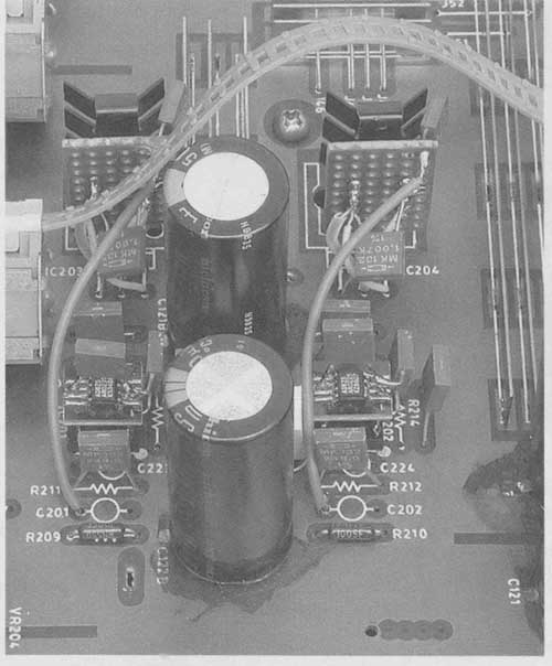
PHOTO 2: The completed line stage using AD825AR op amps and Caddock MK132
resistors.
This external supply houses the AC line filter, power transformer, dual rectifier bridges, D common-mode chokes, and raw DC filter capacitors in an external chassis. Figure 1 shows the schematic for alternate supply and interfacing with the main preamp chassis. Anyone who has made it through the four parts of the original series probably won’t need step-by-step instructions for building this supply, so I offer some general guidelines.
• The Bud 6 x 5 x 4” minibox recommended in Part 1 is too small for the alternate supply. I recommend the Sescom MC-SA metal cabinet, which measures 7 x 6 x 4”. I opted for the black cabinet. The anodizing can pre vent a good ground connection between the various pieces of these modular enclosures. I used small ground lugs, slip-on crimp connectors, and 18AWG hookup wire to ensure a solid connection between the six pieces.
• You can reuse the four HexFred rectifiers installed in the main preamp chassis, plus the four sets of B/C snubbers. You’ll need four more of each for the new supply.
I mounted the rectifiers, B/C snubbers, DC common-mode chokes, and raw-DC filter capacitors on a piece of Circuit Specialists HF Prototyping Board (Photo 3). Use 16AWG solid bus wire to make connections on the board. You can use the same type of bus wire you used to connect the regulator board in Part 2—just remove the insulation. Slip a piece of 1/8” heat-shrink tubing over each HexFred rectifier diode. You don’t need to shrink the tubing—it will be a snug fit with out shrinking.
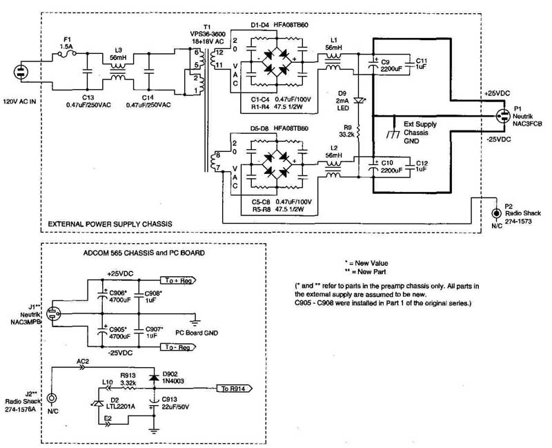
FIGURE 1: Circuit diagram of the alternate external supply and the connections
to the main preamp chassis. This supply houses the AC line filter, power transformer,
dual rectifier bridges, common-mode chokes, and raw DC filter capacitors in
the external chassis.
• You can re-use the 80VA power transformer recommended in Part 1, or try the Parallax/Triad 130VA transformer shown in Fig. 1. I found that a 130VA transformer makes a noticeable improvement in dynamics with this pre amp. As I indicated in Part 1, the 130VA transformer has higher secondary voltages under the load encountered by this preamp. But, having separate rectifier bridges for the positive and negative supplies adds an additional forward drop for each half of the cycle. This eliminates the potential problem of excessive regulator heat due to higher raw DC voltages.
• The AC line filter built for the out board supply in Part 1 can be re-used. I used a 56mH choke for the new external supply.
• Three-conductor, 14AWG SJT cable is fine for the raw DC cable to the pre amp. I chose D.H. Labs Q10 speaker cable, which is Teflon-insulated, silver-plated wire. The Q10 cable is rather stiff and more difficult to work with than SJT. This cable has four conductors, two 14AWG, and two 16AWG. I tied the 16AWG conductors together for the ground wire. I suggest limiting the length of this cable to two feet. The power supply can be situated on a shelf below the preamp.
• Use a Neutrik PowerCon NAC3FCB cable connector, which mates with the NAC3MPB mounted on the preamp chassis. These are the blue/gray Neutrik connectors. Since I used the all blue Neutrik pair for the AC connections in Part 1, I decided to use the blue/gray type for DC They aren't mechanically interchangeable, which prevents accidental connection of the wrong type of supply. I have two pre amps, one with each type of outboard supply, so I don’t want to accidentally mix them up. You could re-use the all-blue pair listed in Part 1, if you like.
=== ====
THE MODIFIED GFP-565 PREAMPS — A SONIC EVALUATION
The three preamps auditioned by Lorelei Murdie were not identical. Preamp #1 is the unit I modified for Victor Cam pos, and the same one auditioned by Ed Dell for his report in Part 4 (Feb. 2004). It contains the outboard power supply described in Part 1 (Nov. 2003) of the series, AD744KNop amps in the line stage, with the output and feedback taken from pin 6, and Holco resistors in the line stage. Preamp #2 is my own reference preamp. It has the alternate outboard supply described in the accompanying article, with the AD825ARop amps and Caddock MK132 resistors in the line stage. Preamp #3, my secondary preamp, is identical to #1 except for AD825 op amps in the line stage. Lorelei’s own preamp is an Adcom GFP-565 with one minor modification: over 12 years ago I replaced the LT1056 op amps in the line stage with Linear Technology’s LT1 122. This was an incremental, rather than a dramatic, improvement.—G.G.
REFERENCE RECORDINGS:
(All listening was done using compact discs). Mussorgsky /arr. Ravel: Pictures at an Exhibition. Chicago symphony Orch., Fritz Reiner, cond. JVC JMCXR (XRCD2). Rimsky-Korsakov Scheherarad& Stravinsky: Song of the Nightingale. Chicago Symphony Orch., Fritz Reiner, cond. RCA Victor Living Stereo 68568-2 (UV22-Encoded Gold Edition). The French Touch. Boston Symphony Orch, Charles Munch, cond. RCA Victor Living Stereo 68978-2. Verdi: Requiem. Joan Sutherland, Marilyn Home, Luciano Pavarotti, Martti Talvela, Vienna Philharmonic Orch., Georg Solti, cond. London 411 944-2. Honkytonkville. George Strait. MCA Nashville. B000011402 Red Dirt Road. Brooks & Dunn. ARISTA. 67070-2
LISTENING CRITERIA:
1. Comparisons: When listening to each preamp, my husband Randy and I were mostly comparing the new preamp to our very slightly modified preamp, which we have used for 14 years. While previewing these preamps, there were times—especially with the classical CDs—that I thought about the natural sound of the instruments. As a concert hail manager in a complex that supports over 300 events per year, I hear so much live music that it is hard for me not to compare this sound as well. For example, I know the sound of a set of cheap tympani and the sound of a set of professional-grade timpani. I also know how a piano sounds under the hands of Loon Fleisher versus a college freshman piano major.
2. Soundstage: For my own enjoyment, I like to close my eyes while listening to music and pretend I’m in the concert hall listening to the music live. The clarity of the soundstage, width, and depth make a big difference to my listening pleasure.
3. Volume: We listened to every CD with the volume control pointing to ten o’clock. We rarely listen to music over that level. When listening at 10:00, it is difficult to have a conversation (especially when listening to a country music CD). I think ten o’clock is as loud as our system can go without distortion.
4. Dynamics: When listening to live music, you realize that sound level is never dynamically flat. There are always subtle crescendos and decrescendos being played as well as the more obvious dynamics when the piece as a whole becomes louder and softer. To hear them more fully on a system increases the listening enjoyment and makes the recordings sound more musical and natural.
5. Detail & Definition: This includes hall acoustics, articulation, low-end punch and cleanliness, high-end brightness, and how well the instruments sound together.
6. Overall: Warmth, tone quality, and tonal balance can make a big difference to listening enjoyment and naturalness of sound. For example, if the sound level of the bass, midrange, and treble are not similar and the sound system favored one over the others, the recording would not be as natural.
7. Our system: Vandersteen 2ci Loudspeakers, Cambridge Audio D500 CD Player, AudioQuest speaker cables, D.H. Labs BL-1 interconnects, Adcom GFA-545 power amplifier.
TABLE 1
LISTENING TO THREE PREAMPS
PREAMP #1
We have been lamenting the fact that we are using our back-up power amp (an Adcom GFA-545). Our old reference amp (an Adcom GFA-585) bit the dust a few months ago. Adding this preamp (#1) to our system has changed the way we feel about our system as a whole. We were no longer lamenting our plight but are excited to listen to our recordings again. Our CDs sound more like our old system and in many ways even better!
This preamp has much more detail. In Solti’s Verdi Requiem (this happens to be one of my favorite recordings, which I have listened to many, many times), there is a section at the end of the “Lacrimosa” where the basses are singing low notes with the orchestra. I have never heard the bass drum playing along with the men the way I heard it with this preamp. I remember being surprised to hear this with such clarity and definition. The soloists also stood out more and their articulation was more pronounced.
In Reiner’s Pictures at an Exhibition the first thing I heard was the sound of the recording equipment. I had never heard that be fore in this CD even with our old reference amp. The hail ambience was more pronounced and woodwind sound was warmer. The trumpet sound at the beginning was cleaner and clearer. The sound stage opened up with this preamp, and with greater depth. What I kept hearing over and over again—and I think what impressed me the most—were the dynamics.
AU of my recordings in general sounded more musical with this preamp, which greatly increased my listening pleasure. The subtle crescendos and decrescendos were much more pronounced. The low end was tighter and more prevalent. We were missing this with our GFA-545 because it doesn’t have the low-end punch and control of the GFA-585. Also, I noticed that the sound level in general was louder at ten o’clock than what we were used to. This is surprising, since Gary says that the modified preamp has less than half the gain of the Adcom original.
My husband listened to this preamp for five minutes before saying, “How do we get one of these?” He was listening to his favorite recording of George Strait. Don’t cringe just yet.
Now, I realize that it is very hard to reference the sounds, as no one really knows exactly what it is supposed to sound like. We did attend a George Strait concert and sat in the third row last year. I remember having my fingers in my ears most of the time because it was so loud. I also remember commenting to my husband that it sounded better at home.
Anyway, my husband said this preamp made George sound even better. He enjoyed hearing instruments in the recordings that weren’t as noticeable with our old preamp. The background instruments stood out more with this preamp. His comment was that he could hear more detail and clarity, especially in the soundstage.
PREAMP #2
If our old preamp was a Chevrolet, preamp #1 would be a Cadillac, and this preamp would be a Rolls Royce. We were blown away by the sound of our system with this preamp installed. Everything we played sounded great. Our system has never sounded this good.
We have a few CDs (most of them are in my husband’s collection) that I considered unplayable on our system at 10:00. I think they were recorded for cheap CD players and the recordings are “hot” or very bright. This preamp made them sound good!
One such example (and I don’t recommend that you go right out and buy this CD) is a country CD of my husband’s called “Rod Dirt Road” by Brooks and Dunn. It is so bright that it hurts to listen to it at ten o’clock. Your ears fatigue quickly listening to this recording with our old preamp, and to a lesser degree but still problematic with preamp #1. With this preamp, the whole system was able to play this recording and it sounded good (well, if you like country music)! My husband’s comment about this preamp was that even though he had been listening to these same country music recordings many, many times, he believed he was listening to different recordings now because with this preamp #2 he could hear things he had never heard before.
Listening to The French Touch, I was impressed by the volume of sound at ten o’clock. This preamp is louder than preamp #1 and without distortion. It is so smooth sounding. The low end is amazing. You get more low end but it is controlled and tight. The balance of high, mid, and low end is wonderful. You don’t get a sense that any of them overpowers the other. You just get more.
While listening to Verdi’s Requiem, I couldn’t help but notice how much more I could hear the singer articulation. The sound stage with the Preamp is bigger and has much more depth than even preamp #1. This is a most impressive preamp. We did not want to see it go. I couldn’t believe how wonderful our system sounded even with our backup power amp.
PREAMP #3
Well, I’m sorry to say that we heard preamp #3 after preamp #2, be cause all we could think about was how wonderful preamp #2 sounded. I would say that this preamp is slightly better than pre amp #1, but a far cry from preamp #2. I noticed that the sound is a little warmer than preamp #1. There is a slightly larger and deeper soundstage than preamp #1.
To give an example, compared to preamp #1, the trumpet sound in Pictures is slightly better (fuller and warmer), and I noticed that the snare drum sounded tighter and clearer than with preamp #1. This is a wonderful preamp similar to preamp #1. I would say it is 25% better than preamp #1, but about 75% away from preamp #2.
OUR PREAMP
It has been three weeks since we last heard our preamp. Our first reaction to the switch back was, “The grunge is back!” The sound wasn’t as clean. The soundstage was smaller and shallower. The volume level wasn’t as great at ten o’clock.
Also, I missed not hearing the subtle crescendos and decrescendos of the borrowed preamps. This preamp just doesn’t have the musicality of the other preamps. We’re back to lamenting our fate and lack of our reference power amplifier. We both considered it a privilege to hear these preamps.
NEW POWER AMPLIFIER
Another three weeks have passed. We purchased a new power amplifier—an NAD S200. It is wonderful (and at $1750 plus tax it should be). Our system has power again. We hear wonderful dynamics, more low and high ends, larger soundstage, and more detail.
I asked my husband last night—after listening for four to five hours each night for three days—one question: “You have heard our system with preamp #2 and our backup power amplifier. You have now heard our system with our unmodified Adcom preamp and NADS500 power amplifier. If you had to choose between the two systems, which system would you rather listen to?” My husband’s response after a brief pause was, “I’d rather listen to preamp #2 and our backup power amplifier.” I agree with him. We both decided (independent of the other) that preamp #2 patched into our system just sounded better and was a more enjoyable listening experience!
====
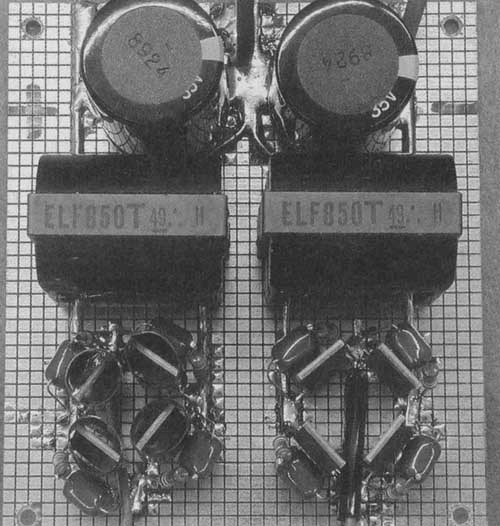
PHOTO 3: The dual rectifier bridges, RIC snubbers, DC common-mode chokes,
and raw DC filter capacitors are mounted on a piece of Circuit Specialists
RF Prototyping Board.
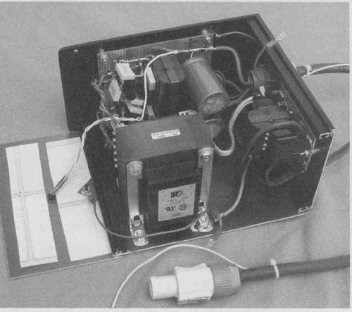
PHOTO 4: Inside view of the external DC supply. The power transformer is
in the foreground, with the rectifier board behind it, mounted on the side
panel of the chassis. The AC line filter and line fuse are mounted on the
rear panel. A separate 1 8AWG wire provides the connection to the muting circuit
bias supply.
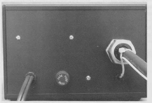
PHOTO 5: Rear panel of the external supply, showing the main DC cable, bias
supply wire, AC fuse holder, and AC power cord.
• The connection for the muting circuit bias supply must be made with a separate wire connected to the power transformer (Fig. 1). I used a Radio Shack 274-1573 cable-type DC power connector for the external supply, which plugs into their 274-1576A chassis connector. Note that only the center pins of these connectors are used—there isn’t a separate ground connection for this supply. If the muting circuit bias supply is not connected, the preamp will be in a permanent state of mute.
• Photo 4 shows the inside view of the external supply. In his sidebar, the author correctly noted a slight mechanical buzzing in the case of the external supply. I suggest Armstrong self-stick floor tile to damp chassis vibration from power transformer, and I placed a piece of 1”-thick foam between the top of the transformer and the chassis top plate. This pretty well eliminates audible buzzing from the transformer.
After the external supply is completed, you should test it before connecting it to the preamp. Raw DC at the supply output should be ±27V with no load. The 2mA LED is the pilot lamp for the external supply. It will also drain the raw sup ply if it is powered up without being connected to the preamp. Discharge takes about two minutes after AC power is disconnected. Photos 5 and 6 show two views of the completed external supply.
Now, a few comments about the main preamp chassis modifications:
• No rectifiers, snubbers, or DC common-mode chokes are mounted inside the preamp chassis. They have all been moved to the external supply.
• Mount the Neutrik PowerCon chassis connector between the fuse holder and the AC line cord, as in Part 1. Mount the Radio Shack DC power connector for the bias supply next to the switched, fused AC outlet on the GFP-565 preamp chassis (Photo ).
• Use 14AWG wire—or individual conductors from the D.H. Labs Q-10 speaker cable—between the Neutrik chassis connector and the main PC board. If you used the D.H. Labs cable, parallel the two 16AWG conductors for the ground connection (Photo). Carefully observe DC supply polarity! Connect the muting circuit bias sup- ply with a short length of 18AWG hookup wire between the Radio Shack DC chassis mount connector and the AC2 hole on the main pre amp PC board (Photo).
After completing the preamp chassis modifications, recheck all wiring, making sure that you have DC polarities correct from the external supply to the main preamp PC board.
Connect the new external supply to the preamp, power up, and recheck the raw DC voltages and all regulator volt- ages, as described in Part 2. Under load, the raw DC voltages will be ±25V. If the preamp pilot LED glows dimly, the muting circuit bias supply probably isn’t connected. When you install the pre amp in your system, plug the AC line cord from the external supply into the switched, fused outlet on the back of the preamp, or directly into a switched power line filter.
A while back, I asked Lorelei Murdie, my audiophile friend and colleague at The Crane School of Music, SUNY Pots dam, whether she would be interested in listening to three of the modified pro- amps and offering her observations in print. Since she has owned an Adcom GFP-565 preamp for 15 years, I thought she would be a good person to offer a third-party evaluation. Lorelei is the facilities manager at Crane, a musician by training, and, like myself, she hears live, unamplified music nearly every day. She has a very revealing audio system, and great ears. Her comments appear in the accompanying sidebar.
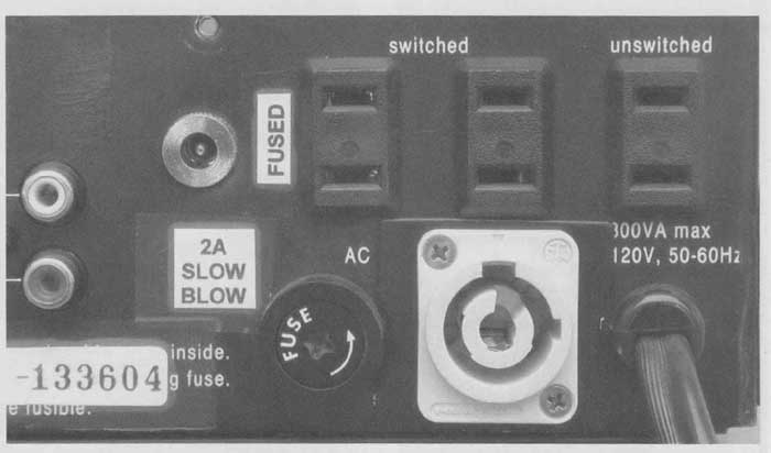
PHOTO 7: Rear panel of the GFP-565 preamp modified for the alternate external
supply. The raw DC connections are made with the Neutrik PowerCon chassis
connector mounted between the AC line cord and the fuse holder. A Radio Shack
DC chassis type power connector, mounted to the left of the switched and fused
AC outlet, is used for the muting circuit bias supply connection.
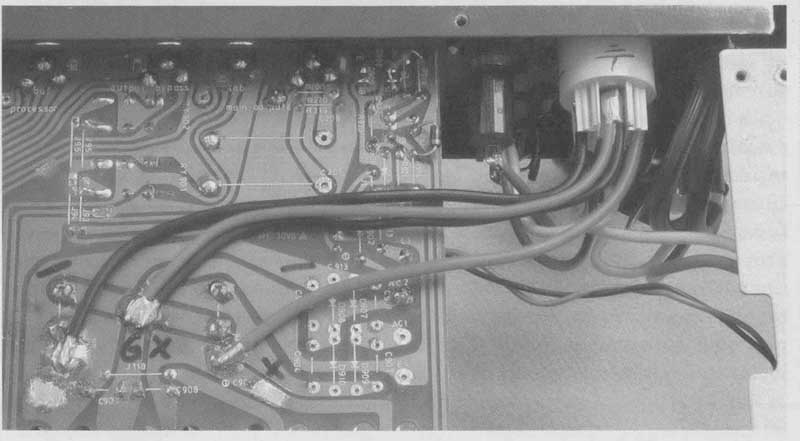
PHOTO 8: Inside the preamp, bottom view, showing the DC supply connections
to the main PC board.
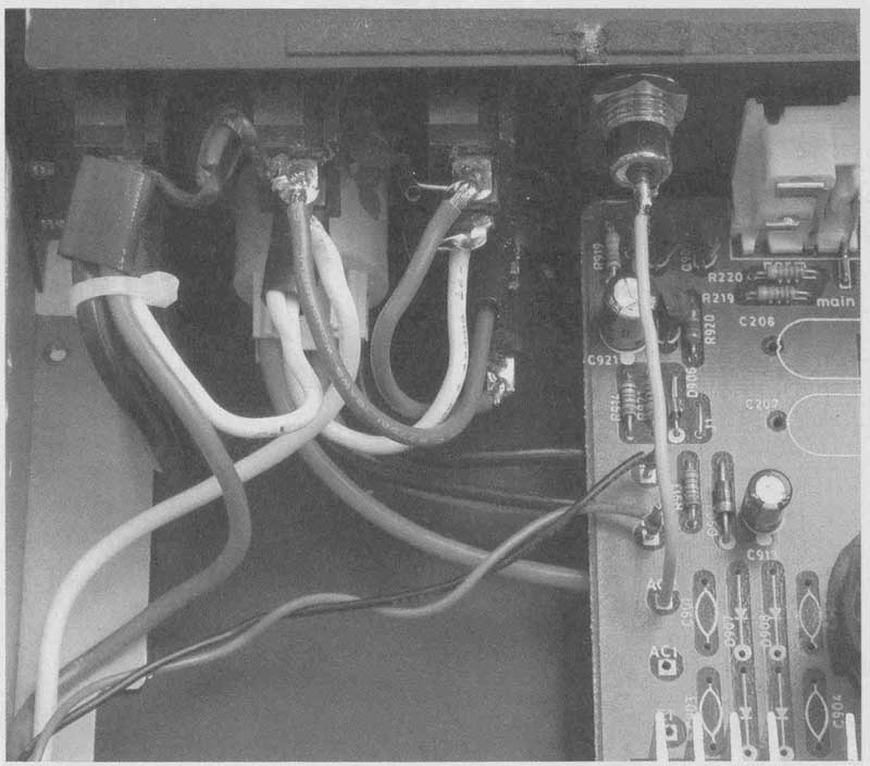
PHOTO 9: Inside the preamp, top view, showing the muting circuit bias supply
connection to the AC2 hole on the main PC board.
============