|
|
Let's build an embedded hardware/software system for 16-bit digital audio!
If you work on electronic designs, then you've probably had to make a decision about dividing your project between hard ware and software. The duality of hardware and software has some similarities to dualities in physics such as mass/energy and wave/particles.
Back in 2003, I built myself a simple MP3 player. The main part of the project was a specialized chip for performing MP3 decoding. Since then, significant progress has been made in audio and chip technology. Thus, it's possible to build a similar media player with more simple hardware and more powerful software. A great example of such a system is the digital audio player I'll describe in this article. The system is an embedded hardware/software solution for 16-bit digital audio.
PROGRESS IN DIGITAL AUDIO
During the past few years, a great deal of progress has been made in the field of digital audio system technology. Let's focus on the three main areas of development.
First, consider the quality of em bedded ARM-based microcontrollers.
These devices have enough processing power for the software decoding of MP3 and other compressed file for mats in real time.
Progress has also been made in mass storage device technology. The affordable, easy-to-interface SD card has become one of the most popular (a de facto standard) types of memory.
The USB flash disk widely used by PC users is the other popular technology.
Finally, it's clear that a lot of progress has been made in audio codec and DAC technology. More variety, functionality, and lower power consumption are commonly available today.
Sorry, Steve, but "my best software tool is (no longer) a soldering iron."
DIGITAL AUDIO PROCESSING
This is not a poor man's iPod. It's the real McCoy. My digital audio player is an example of digital audio processing in software.
There is often a need for audio in an embedded application, which can be controlled programmatically (by a command on a serial port that can make the system play a suitable tune). The block diagram for generic em bedded audio processing is shown in Figure 1. The blocks used in the project are highlighted.
The user manual for the LPC214x family of NXP microcontrollers (section 1.3 Applications) doesn't list digital audio in its other applications, but you don't need to tell NXP Semi conductors what you're using it for.
The SPI port on LPC214x microcontrollers doesn't support I2S mode, but that's easy to fix.
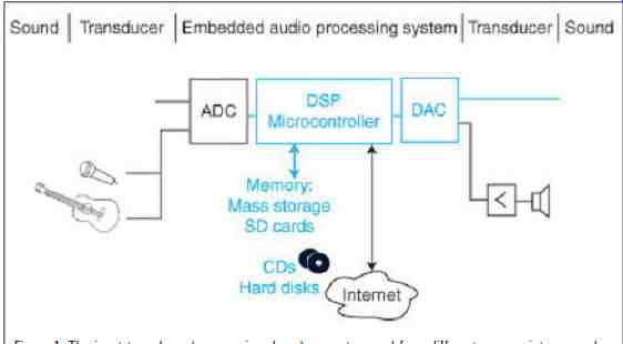
Figure 1: The input transducer (e.g., a microphone) converts sound from
different sources into an analog signal. The ADC converts the analog signal
into a digital signal. The DSP system with its resources does the processing,
and it outputs the resulting signal into a DAC. To output sound, the DAC
sends the analog signal into the speaker or headphones.
DIGITAL MEDIA BASICS
Digital media technology is constantly evolving. To implement it, you need a good grasp of the terminology used in the field. There are several useful publications and web resources for broadening your knowledge of digital media technology. David Katz and Rick Gentile's Embedded Media Processing is one of my favorite re sources. In this section, I'll briefly describe some basic terms.
Sound is a wave form of energy that propagates through air or some other medium. Amplitude and frequency are the two attributes that define sound. Music is an art form, which involves structured and audible sound.
Although the definition is seemingly subjective, it's the most common.
What's music to one person can be noise to another.
The audio signal can come from a transducer (e.g., a microphone) that converts sound waves into electrical signals, or it can be created (synthesized) electronically. On the other end, an analog audio signal coming to the speaker or an earphone is converted into a pressure change (sound wave).
To process sound, you need to convert both ways between analog and digital signals. An ADC and DAC do this. Devices combining one or more of each are called codecs. Note that the word codec is used for both the hardware devices and software algorithms.
To correctly represent the digital signal, refer to the Nyquist theorem.
(The sampling frequency must be at least twice the highest frequency of the signal.) You can hear sounds be tween 20 and 20,000 Hz, so the sampling rate has to be at least 40 kHz.
The commonly used sampling rate for CD quality audio is 44.1 kHz. The amplitude of sound is measured in decibels. The range for a human ear is from 0 (the threshold of hearing) to 120 dB SPL (the threshold of pain). Dynamic range is a ratio of the maximum signal level to the mini mum signal level (or the noise floor). For digital audio systems, the dynamic range depends on precision (number of bits representing the signal). For 16-bit codecs, the dynamic range is 96 dB. There are standards for connecting physical devices in digital audio systems. The most common are I2S and AC97. The former, which I used for my project, is a three-wire serial interface for the digital transmission of audio signals. It has a bit clock, data, and left/right synchronization lines.
Intel created the popular AC97 standard for PC audio.
The popular audio file formats are wave and MP3. The latter is one of the most popular lossy audio compression codecs that can achieve a compression ratio of up to 12:1. Lossy codecs use a technique called perceptual encoding, which takes advantage of your ears' physiology. Although the data is lost, the decoded sound is close to the original.
AUDIO PLAYER PROJECT
My audio player is an embedded hardware/software solution for 16-bit digital audio. The purpose of the project is to achieve CD-quality audio, which means 16 bits (96 dB dynamic range) and a sampling rate of at least 44.1 kHz. If lower quality is satisfactory, you can use a simpler option.
For example, you can use the onboard DAC (10-bit resolution and a maxi mum speed of 1 µs).
This project has three major functional blocks: a microcontroller, an SD card interface, and an audio DAC interface. The prototype is built around an LPC2148 evaluation board from Olimex and two extra proto type boards: one for audio DAC and one for the SD card (see Photo 1 and Figure 2). Later on, I decided to integrate everything into one board to be a module/building block for use in embedded systems.
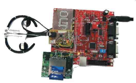
Photo 1: The prototype is built around an Olimex LPC2148 board. I added
two extra prototype boards. One is for the SD card interface. The other is
for the Texas Instruments audio DAC.
=====

Table 1: There are different SP11 clock settings for the various crystals
and sampling rates.
Crystal frequency PCLK = MCLK Audio sampling frequency Hz Theoretical bit rate (Hz) Theoretical clock divider
Real divider CSPDVSR Error
11.2896 MHz 56.448 MHz 44,100 Hz 1,411,200 40 40 0% 12.0 MHz 60.0 MHz 44,100 Hz 1,411,200 42 . 517 42 1.20% 12.288 MHz 61.440 MHz 48,000 Hz 1,536.000 40 40 0%
=====
SYSTEM TIMING ANALYSIS
To achieve CD-quality audio (16 bit stereo with a 44.1 kHz sampling frequency), the required bit rate is 1,411,200 Hz (i.e., 16 bits (resolution) × two channels (stereo) × 44.1 kHz (Fs)). For 48 kHz, the bit rate is 1,536,000 Hz. This is the clock generated by the synchronous serial port (SSP), supplying data continuously to an audio DAC.
With a 12-MHz crystal (as used on Olimex and Embedded Artists evaluation boards), the timing is very close.
The system clock generated by PLL from a 12-MHz crystal is CCLK = 60 MHz.
The other possible crystals are 11.2896 and 12.288 MHz. For NXP Semiconductors LPC21xx microcontrollers, the clock of the SSP is de rived from peripheral clock PCLK, which is PCLK = CCLK/VPB. Its maximum value can equal to CCLK (when the VPB divider is 1). There is another divider hold in the CSP CPSR register to define the clock of the SSP (SCK1).
Table 1 shows some combinations of crystals and settings. If you want to use another clock or sampling rate, you can easily calculate your settings.
The data has to be read from the file on an SD card. The card is in FAT format, and it's compatible with a PC. The data has to be read and processed in real time. The processing required is very simple for uncompressed audio.
It's more complex for compressed audio like MP3, which requires complex decoding.
HARDWARE
Failure is a new success. When I originally built the audio player, I didn't have enough RAM, and I failed to fully address the problem at the time. Fortunately, I eventually came up with a solution.
For this project, there are a few requirements for the microcontroller.
You need at least 40 KB of flash memory and at least 40 KB of RAM. You also need one SPI for the SD card interface, a fast SPI capable of handling at least 16-bit data for the I2S interface, and one UART or other communication channel for connecting to an external system. A few different microcontrollers will work.
NXP's LPC2148 and Atmel's AT 91SAM7S256 are the most popular.
The latter has an SSI module with built-in I2S mode. The NXP micro controller has a Texas Instruments DSP mode. It's no surprise that most audio codecs from Texas Instruments support its data interface with a glueless interface to the SSP on the LPC2148 microcontroller. For more generic solutions, you have to modify it to use the I2S. For that purpose, I've used some of the microcontroller's modules: Timer1 in Counter mode (with external input and output to provide LRCK for DAC) and PWM to generate MCLK for the audio DAC.
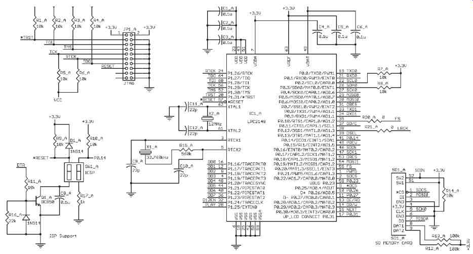
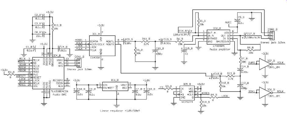
Figure 2: The system's main board is a modified Olimex LPC2148 evaluation
board. Two alternative audio DAC circuits are shown. Use one of them or your
own.
The SD card interface is a standard SPI mode.
If you want to use an operating system in your application, then you'll need an extra timer. If your application has any other user interface, you might need some extra I/O ports.
Two extra prototype boards were attached to the Olimex LPC2148 evaluation board. Let's take a closer look at each one.
SD CARD INTERFACE
The SD card operates in a standard SPI mode. The SPI0 has been used with its maximum clock of 7.5 MHz.
It operates in 8-bit mode using SCK, MOSI, and MISO lines and another port line used as chip select (CS). If you have any ARM7 evaluation boards from Keil, Olimex, IAR, Embedded Artists, or other manufacturers and they already have an SD card interface, you know that they all follow the same rule of using the SSP for that purpose. The idea is probably to give you a faster read/write time, but the better option for this project is to use SSP for the DAC interface. The SSP has an eight-frame buffer (FIFO) and corresponding interrupt source, both of which are not available on SPI0. This means the interrupt occurs more often when using SPI0 instead of SSP. On my prototype built around the LPC2148, I had to rewire it too, which wasn't difficult.
AUDIO DAC INTERFACE
I selected an I2S standard interface for the audio interface because of its popularity (a number of codec chips available from different manufacturers). It's also easy to interface to the microcontroller.
Some audio DACs like the Texas Instruments TLV320DAC26 need extra control signals when initially setting up their internal registers in addition to I2S signals and MCLK. With simple DACs like the Cirrus Logic CS4330-KS, for example, no setup is required. I have tried both of them. Figure 2 shows the circuit for both options.
I used SPI0 lines shared with the SD card and an extra select line for the Texas Instruments DAC control interface. Although it needed 16-bit data, I used two consecutive transfers of 8 bits and it worked fine.
For some extra complexity of control interface, the chip has a built-in headphone amplifier, as well as programmable volume control and other controls. It also has an internal PLL, which gives you flexibility for selecting the external clock.
For an MCLK signal, you can use the microcontroller's crystal (directly or through a buffer) or generate it in side the microcontroller, as I did. The code within the init_hardware() function in the mp.c file on the Circuit Cellar FTP site is used for the BCLK signal to be generated on pin PWM5 (P0.21/PWM5 pin 1).
24-MINUTE I2S INTERFACE
Most audio DACs require an I2S or a similar (left- or right-justified) data interface. The LPC2148 micro controller has two SPIs, but neither of them works in I2S mode. Only one of them (the SPI1 or SSP) is capable of processing the 16-bit data required by the I2S interface. That means you have to use it and do some modification to convert to I2S.
The microcontroller's SSP is used in a 16-bit Texas Instruments DSP mode to make it easy to convert into I2S. Refer to NXP's "LPC214x User Manual" for a description of the possible modes of operation.
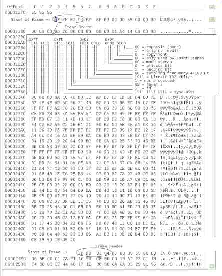
Figure 3: The MP3 file format is in the hex editor.
A few steps are involved with converting from DSP mode to I2S. The data output from SPI1 doesn't need any modifications to be used as I2S data. The left/right clock (LRCK) can be derived from the FS signal in the straightforward manner. The FS signal, which is output on the SSEL1 pin (P0.20/SSEL1 pin55) in TI mode, is connected to the Timer1 input capture pin (P0.10/CAP1.0 pin 35). Using the timer's one input capture and out put match function, the FS signal on the input pin of Timer1 (P0.10/ CAP1.0 pin 35) is converted into an output signal on pin MAT1.0 (P0.12/ MAT1.0), which represents the LRCK signal of the I2S interface.
To complete the I2S interface, the clock must be inverted. This is achieved via the tiny logic inverter (e.g., a Fairchild Semiconductor NC7SZ04). Connect the inverter's input to SCK1 (P0.17/SCK1 pin 47) and its output to BCLK on the I2S.
If you use another DAC with a left- or right-justified format instead of I2S, you can achieve it by slightly changing the I2S modification because they are similar. All of the settings of the internal modules are done once after power-on reset. The code is in the init_hardware() function in the mp.c file. If you plan to use any of the low-power modes, you might need to stop some modules and activate them later during wakeup. If you want to save valuable resources like Timer1 and PWM5 for other purposes, you can use a simple D-latch (e.g., the TinyLogic NC7SZ74) to do the same in hardware.
SOFTWARE
I tried to make the code as simple and as minimal as possible so it would be easy to understand. The code currently supports WAV and MP3 for mats. You can find information about both formats on the Internet if you're interested.
The WAV file format supports a variety of bit resolutions, sample rates, and channels of audio. A WAV file is a collection of a number of different types of chunks. There is a required format ("fmt") chunk, which contains important parameters describing the waveform, such as its sample rate. The data chunk, which contains the actual waveform data, is also required. The other chunks are optional.
The minimal WAV file consists of a single WAV containing the two required chunks: a format chunk and a data chunk. There are a number of variations on the WAV format, but if you convert from CD to WAV format, then most of the software will create the simplest WAV file.
MP3 is the other popular audio file format for compressed data. MP3 files are composed of a series of frames.
Each frame of data is preceded by a header, which has extra information about the data to come. Extra information, which is called ID3 data, may be included at the beginning or end of an MP3 file. Figure 3 shows the MP3 format with a hex representation of bytes and an explanation. You can investigate it by opening the file in any hex editor. I use WinHex because it has a disk utility as well.
HALF EMPTY
The SSP provides a continuous stream of 16-bit data for the audio DAC. The presence of the eight frame FIFO and the Tx FIFO half empty interrupt makes for an easy data-loading scheme (see Listing 1).
I created a large buffer for storing PCM data that acts as a circular buffer. One pointer manages the writing into the SSP transmit FIFO (and later audio DAC). Another pointer manages the loading of new data from the SD card. For uncompressed audio files on input, the loading comes directly from the WAV file. For MP3 files, the data has to be decoded be forehand.
The simple synchronization is achieved by checking the distance between pointers with software. The software functions related to the SSP are the initial setup, ISR, and buffer loading functions. (The SSP's receive function isn't used at all, so the Rx of the at least half full interrupt is disabled.)
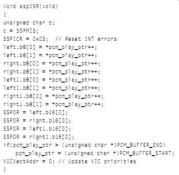
Listing 1: Take a look at the interrupt service routine for the Tx FIFO
half empty interrupt. The sequence of four 16-bit words is written into the
transmit register from the PCM buffer. The data in the buffer comes either
directly from the wave file or from the output of the MP3 decoding function.
CARDS ON THE TABLE
Almost everyone knows how to use and program an SD card. There are a number of examples freely avail able. The embedded file system library (EFSL) is very popular. I used bits and pieces of my old code for the initialization and reading of files.
My code covers only FAT16, but it's rather small and uses very little RAM.
I put the open-source software for MP3 decoding into a separate directory (\fixpt) as part of CrossWorks for an ARM project. The compiler is based on GNU. There is a nice debugger in the package for easy development. Rowley offers a fully functional, time-limited evaluation version.
I was positively surprised that I had only a few compilation errors.
After commenting out some unnecessary statements, everything compiled smoothly.
I haven't used the dynamic memory allocation, but I have a rather static memory assignment. As a result, my mp3_init function is different, but you can do it either way. A dynamic allocation is more elegant because you can free up the memory for other uses.
My SD_play_mp3() function is based on the open source example. Only three functions from the package are called: MP3FindSync Word(), MP3Decode(), and MP 3GetLastFrameInfo(). I created the myFillReadBuffer() function to handle the readings from the SD card and filling the input buffer.
I usually use the "It's not you, it's me" approach when something doesn't work. After fixing some bugs in my code, everything worked fine and I didn't have a need to go any deeper into the MP3 code. If you're curious about how it's done, browse through the code and read the comments.
If it doesn't work, you're not hit ting it with a big enough hammer. If your hardware is identical or similar to mine, you might first try to load the hex code using the NXP ISP utility. If it works and you need to make changes, you can rebuild the sources.
Remember to turn on the optimization for the MP3 code in the GNU compiler. The "-Os" option worked for me.
There is no embedded video included in the project yet, but don't be surprised if it's as easy to do in the near future as it is to do today with embedded audio (that's if Moore's law still applies). I've always admired people with artistic ability. Although embedded system design is more of a craft than an art, you can still make everything work well and look good.
FACE THE MUSIC
There are limitations in the current version, but you can extend or modify it to suit your application. There might be bugs in my code, so feel free to modify that too. The music can be good or bad, but embedded systems come in a variety of flavors.
Set the volume control below the threshold of pain and let the electrons and holes inside the silicon do the job. Here in Australia, I typically tune in to the Triple J radio station (105.7 FM), where the music is not only good, it's fresh.
RESOURCES
Embedded Filesystems Library (EFSL): www.efsl.be
...and:
http://sourceforge.net/projects/efsl/.
D. Katz and R. Gentile, Embedded Media Processing, Elsevier, New York, NY, 2006.
A. Sloss, D. Symes, C. Wright, ARM System Developer's Guide, Elsevier, New York, NY, 2004.
Texas Instruments, Inc., "Low Power Stereo Audio DAC with Headphone/ Speaker Amplifier," SLAS428, 2004.
M. Thomas, "Interfacing ARM Controllers with Memory Cards," 2006.
SOURCES
LPC2148 Evaluation board Olimex www.olimex.com
LPC2138 Microcontroller
NXP Semiconductors www.nxp.com
CrossWorks for ARM Rowley Associates www.rowley.co.uk
WinHex Hex Editor
====