|
|
In the 1970s, many electronics manufacturers, including Japanese Hitachi, Toshiba, Matsushita, and so on, produced various audio equipment. It was the heyday for audio lovers. The products were later abandoned and turned to junk units. They are available at incredibly cheap prices on Internet auction markets.
I found a nice Hitachi semiautomatic analog record player for only 1,000 JPY (about $12.50). The reason for the cheap price? The pickup did not have a head. After I received it, I realized the tonearm was broken. Junk is junk! I purchased another junk player of the same type equipped with the arm and head. In Japan, it is popular to pick up usable parts from two units then make a perfect one. We call this "2 ko 1," meaning two into one.
UPGRADE
It then made sense to upgrade the player rather than simply restore it. I was determined to convert the player to an "active" system by installing an equalizer with a power supply inside the player. The player, a Hitachi SP-10, is small and the inner space is mostly occupied by the semiautomatic gear (see Photo 1). It looked prohibitively difficult to install the amplification units inside the player (see Photo 2).
After I measured the vacant space left inside, I realized that the only way to equip electronic units inside was to divide the PCB into three parts: a main power supply, a regulated power supply with ripple filter, and an equalizer, which you should place right under the tonearm to prevent noise and realize good sound reproduction without unnecessarily long wiring (see Photo 3).
This guarantees pure sound and suggests why most professional turntables are made this way. You would no longer be tempted to choose expensive shielded cable with gold RCA pin plugs!
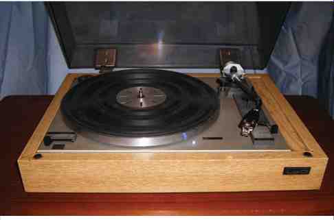
Photo 1: This is a front view of a modified turntable. The blue LED indicates
that the player system is on.
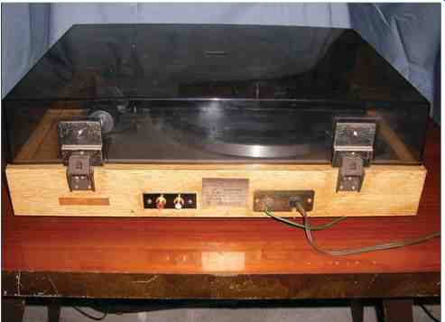
Photo 2: Rear view of the modified turntable
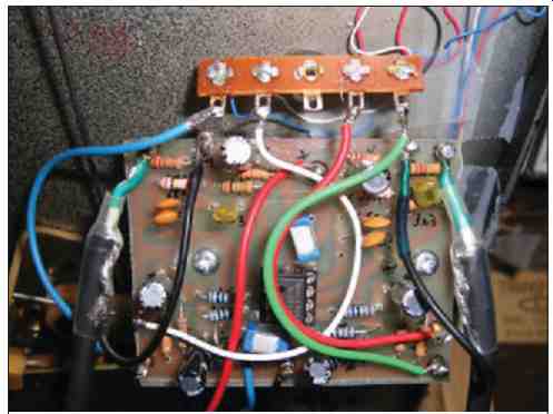
Photo 3: Phono equalizer PCB placed under the pickup arm
SIMPLE CIRCUIT
The rather simple circuit adopted here is not a so-called DC type amplifier, which is fine for a digital system (see Figure 1).
But if you applied the method to an analog LP equalizer, it would feed a horrible low frequency generated by a warped black disc to an honest modern speaker through a DC amplifier. You can see the speaker woofer weirdly trembles, and higher frequency reproduction is affected with intermodulation distortion. An old "good" LP record system lives in a world rather different from a modern digital system.
The three PCBs are equipped with connectors for easy maintenance, as with most professional components. I hand-drew the printed circuit board-quite an old-fashioned way, but reason able for a single product (see Photo 4).
I have referred to the Voltage Regulator Applications Hand book, (Fairchild Semiconductor, 1974), for the application of the regulated power supply with ripple filter (see Figure 2). Because the phono equalizer has a large gain, it is advisable to install the ripple filter (see Photo 5). Here, small transistors are doped to work for this purpose. In theory, the cap value of C9/C11 is multiplied by the transistor's small signal (Hfe) forward current gain (see Figure 3).
I borrowed the topology from a McIntosh C33 pre-amp, with alteration to the value of RIAA net work elements. McIntosh is a great amp; however, I believe the network impedance is very low, which may be too heavy for the OP-IC. Therefore, I ad opted a popular CR value. D11/D12 is designed to protect C16/C17. In case over -0.6 V appears across the cap, the diode works as a short circuit. Place C26/ C27 close to IC pins 8 and 4, respectively, to prevent unnecessary oscillation.
I kept the outlook as it was with one exception--adding a blue LED on the deck to indicate the system is connected with mains. The amplifier is always "ON" because it has no AC switch, while the motor is supplied with AC only when the pickup is in operating position. ( Hitachi designed it that way, which I think was wise.)
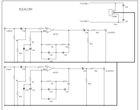
Figure 1: Equalizer circuitry
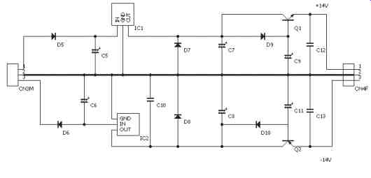
Figure 2: Regulated power supply with ripple filter
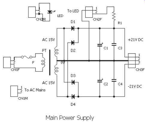
Figure 3: This is the main power supply. The unregulated DC 21-V positive
and the 21-V negative is made from AC 15 V × 2 via D1 through D4
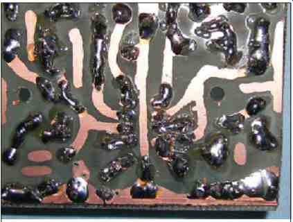
Photo 4: Hand-drawn PCB
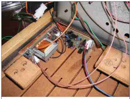
Photo 5: The PCB (left) with a transformer is the main power sup ply. The
other PCB (right) is a regulated power supply with a ripple filter.
=======
Parts & Components
Capacitors:
• C1,C2 100 µ 50 V
• C3,C4 0.1 µ MKH
• C5,C6 330 µ 45 V
• C7,C8 4.7 µ 24 V
• C9,C11 220 µ 24 V
• C10,C12,C13 0.1 µ MH
• C14,C15,C24,C25 10 µ 35 V
• C16,C17 22 µ 16 V
• C18,C20 680 P Ceramic
• C19,C21 68 P Ceramic
• C22,C23 3300 P Polyester Film
Resistors:
• R1 3.3 kO 0.5 W
• R2,R3 150 kO 0.25 W
• R4-R7 1 kO 0.25 W
• R8,R9 100 kO 0.25 W
• R10,R11 1 MO 0.25 W
• R12,R13 220 O 0.25 W
• R14,R15 2 kO 0.25 W
• R16,R17 68 kO 0.25 W
Miscellaneous:
• PT Transformer 15 V 0.5 A × 2
• D1-D12 1N4002
• LED Blue
• CN1M 2P Male Connector
• CN1F 2P Female Connector
• CN2M 2P Male Connector
• CN2F 2P Female Connector
• CN3M 3P Male Connector
• CN3F 3P Female Connector
• CN4M 3P Male Connector
• CN4F 3P Female Connector
• F Slow Blow Fuse 0.5 A
• IC1 Voltage Regulator 15 V Positive 7815
• IC2 Voltage Regulator 15 V Negative 7915
• IC3 OPIC NE5532
• Q1 2SC1567
• Q2 2SA794
=======
PHONO CARTRIDGE
The original Hitachi pickup cartridge is no longer available. Because the arm is designed to accommodate its Hitachi genuine cartridge, the arm has no elevation height adjustment. The original phono cartridge is rather short in terms of height; therefore, if you look for any alternative, choose one with low height.
I tried a SHURE V15-Type 5 MR, and found it suitable.
The record player generates equalized signal with the output level almost identical to CD players. The idea to install an equalizer in the record player is common among professional analog record players; and you may adjust RIAA elements after you measure the actual frequency response in accordance with your cartridge so you can enjoy the total sound quality.
It seems to me that using this method, you can upgrade any old popular analog LP player, not just Hitachi units. You'll be surprised how cool an equalizer installed in the player sounds, eliminating noise without dropping any fine signal.
Discover for yourself how you can create a beautiful player system from junk units.