|
|
.This box allows you to perform precise level-matched comparisons and evaluate a component’s intrinsic fidelity. The unit provides “blind” or “sighted” listening, with automatic or manual switching, and switchable A/B status lights. Buffered line and headphone outputs are provided.
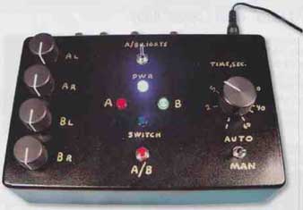
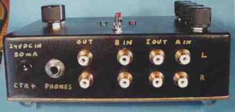
Above: Two views of the A/B/I testing switch box + headphone amp.
I’m well aware of the controversy surrounding blind instant-A/B versus normal (extended) listening comparisons. However, this box serves both purposes. For normal listening, the unit can function as a simple (but high quality) buffered line stage with two selectable inputs, and a moderate power (but also high quality) headphone amp. But my reason for designing it was to be able to instantly and accurately compare the “sound of” (more properly, the sound of music through) two components, or compare a component’s output versus input signals. The latter I refer to as an “intrinsic fidelity” test.
FUNCTIONAL DESCRIPTION
A double-pole (for stereo) relay selects between the “A” and “B” inputs, each with a precision level-matching pot. The selected outputs are buffered by the high-quality OPA627 op amps, which can drive the 300-ohm Sennheiser HD650 headphones to 114dB peak, 100dB typical average SPL.
For intrinsic fidelity testing, the stereo music source is connected to the “A in” jacks (Photo 2). Paralleled with these are the “I out” jacks, which connect to the component’s inputs. Then, the component’s outputs connect to the “B in” jacks. After level matching, A/B switching allows direct and instant listening of the component’s output versus input signals.
Switching is performed two ways:
Automatic: A low-frequency oscillator toggles the relay between “A” and “B,” with adjustable times from one second to one minute spent in each A/B position. A blue LED emits a quick flash at each switching transition. Two status LEDs (red for “A,” green for “B”), when switched on, let you know which source is on. But by leaving these off, and not listening (nor looking at the blue light) for a while, then you can listen with out knowing which source is connected. The blue light tells you when the source changes, but you can listen for differences without preconceived expectations.
Manual: Here, the relay stays in one position indefinitely, until you push the “MAN A/B” switch, which flips the relay to the opposite selection. The three lights function as just described.
CIRCUIT DESCRIPTION
Figure 1A shows the audio path. The op amps have a gain of 2 (6dB) to accommodate the level-matching pots P1- 4 (linear taper 10-turn), initially set to their midpoints. R1 and R7 provide a ground path for the op amp inputs during the 3mS break-before-make relay switching times. R2, C and C2 (left) and R8, CS, and C6 ensure HF stability of the opamps. (C3, 4, 7, 8 must be grounded close to them.)
LEVEL MATCHING POTS
Do not use 10-turn wirewound pots greater than the 20k value specified. These have much higher capacitance than continuous-element pots; this would produce rotational-dependent 10 - 20kHz errors. With the 20k pots, 20kHz error is ±0.1dB.
SWITCHING CIRCUIT
As shown in Fig. 1B, U3 implements the conventional “workhorse” triangle/ square wave oscillator, when switch S1 is set to “Auto.” An integrator (U3A) and positive-feedback latching comparator (U3B) are interconnected in the familiar “tail-chasing” circuit. Assume that initially the output of U3B is somewhat negative, and C9 is discharged.
This is fed through R15 to the non- inverting input of U3B; the resulting positive feedback (FB) makes the out put quickly saturate at about -10v. R14 isn’t needed for the "Auto" function; I’ll describe that later. This -10V, through P3 and R16, makes the integrator cap C9 start to linearly charge (U3A output rises in a positive direction).
When the U3A output voltage reaches about +5V, this through R13 is enough to overcome the negative voltage (through R15) so that U3B pin S (non-inverting input) becomes positive. This quickly flips the U3B output to about +10V, making the integrator output (U3A pin 1) start ramping negatively, reversing and indefinitely repeating the cycle. The output of U3B is thus a square wave of about ±10V amplitude, with frequency adjustable by PS.
MANUAL OPERATION
With S1 in “MAN,” there’s no negative FB from the integrator, so U3B stays latched wherever it was (+ or -by) be fore opening Si. Assume it’s at +10V. R20 and C10 form a lowpass filter with a 0.1 second time constant, fast enough for C10 to charge close to the square-wave levels of U3B output even at the fastest (1 second) auto-switching rate. Depressing the push-button S2 discharges C10 into R18 + R19 quickly (1.8mS time constant).
This lasts long enough to flip the latching polarity of U3B output from +10V to -10V. It does this by developing about +5.5V at the inverting input (pin 6). The purpose of R14 (mentioned previously) is to attenuate the positive FB voltage at pin 5 (from R15) to about +2.5V (when U3B output was +10V), so the +5.5V at pin 6 can reverse the opamp output polarity.
Pushing S2 appears to activate negative FB that could stabilize the op amp output to near ground. However, the 1M-ohm value of R20 is much too high (in regard to R18) to develop enough steady-state negative FB to overcome the latching positive FB of R15 and R14. The capacitive discharge action of C10 ensures reliable A/B toggling of S2, immune to contact bounce or holding S2 on.
STATUS AND SWITCHING LIGHTS
With S3 on, a negative output from U3B (corresponding to selection “A”) turns on the red LED1; a positive out put (“B”) turns on the green LED2. R22 equalizes the brightness of LED2 (it is brighter than LED1 with equal currents). When the output of U3B switches polarity, a current pulse through C11 and R23 is full-wave-rectified by diode bridge D1-4 to make the blue LED3 flash. While the C11/R23 time constant is l8mS, the ever-increasing resistance of the LED (as its current decays) pro longs its flash decay to about 1% second, which I find more pleasing than an abrupt turn-off.
POWER SUPPLY
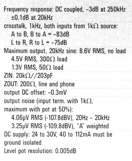
A 24V DC “wall wart” is used, with ground-isolated input jack (J10). This is passively split into an (approximately) ±12V ground-referenced supply by D5, biased through R24 and LED4. This simple supply is more than adequate because of the audio opamps’ 120dB power supply rejection ratio (PSRR). Nevertheless, large filter caps (C12, 13) bypassed with film caps (C14, 15) are used.
A note on the violet “Power” LED:
These are available from Bivar (949-951-8808). Glowing a deep purple, they look beautiful in the dark. The datasheet says “Caution--ultraviolet.” However, the wavelength is 405 nanometers (nm), which is at the violet end of the (obviously) visible light spectrum. Any actual ultraviolet sideband power is far less than that entering a window even on a cloudy day (near-UV is transmitted through window glass), and much less than that emitted by nightclub fluorescent “blacklights.”
You can substitute other LEDs, but with the approximately 20mA bias current, you should use a low-sensitivity LED to avoid being too bright. Or, you can eliminate this “frivolous decoration” by changing R24 from 470 to 680-ohm, ½W, grounding its lower end.
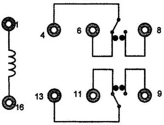
FIGURE 2: Relay connections, bottom view.
CONSTRUCTION
Figure 2 is a bottom view of the relay connections. Figure 3 is the panel component hole layout. I used a 6 s/s” x 3 /8” piece of solid copper (unetched) /16” PC board material, with holes drilled to match the top panel holes. The panel pots and switches then hold the board in place. I soldered and wired the parts on this ground plane board. You can make a conventional PC board with this same hole layout.
Before installing the board and panel components, I spray-painted the box with three coats of Krylon ultra flat black, then two coats of Krylon Crystal Clear. Because this insulated the top panel from contacting the pots and switches, I soldered board ground wires to three of the audio jack ground lugs. Note: If you use the specified gold-plated RCA jacks, don’t use the chassis-insulating washers.
I hand-lettered the box with a Pilot gold marking pen (available at Rite Aid). I also used this on the box cover’s rim, visible on the bottom.
COMPONENT CONNECTION METHODOLOGY
When two components are being A/B compared, their inputs are paralleled to the music source, and only their outputs are switched. In addition to avoiding the need for a second relay, there’s an additional advantage: Both components are continuously “exercised” with the music. If the components are sensitive to power supply sag, or exhibit slow-acting signal compression for any reason, then switching their inputs on and off at random intervals (possibly unequal) could un fairly bias their evaluation. Driving both components’ inputs continuously (as in normal usage) allows any “warmup” or other long-term effects to stabilize.
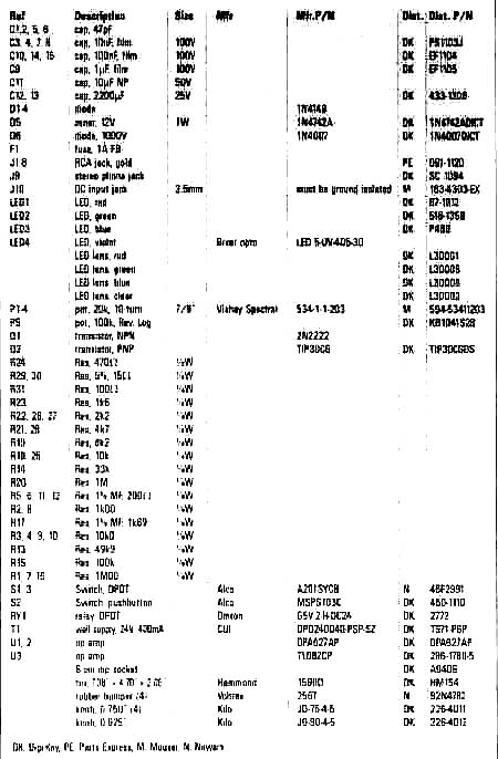
ABOVE: Table 2 is the parts list.
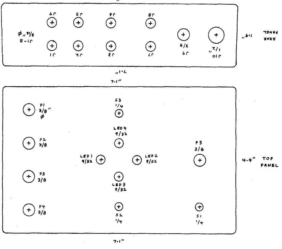
FIGURE 3: Hole layout on Hammond 1590D box.
USING THE SWITCH BOX FOR A/B COMPARISONS
Note: When testing power amps, make sure the input pots on the switch box (P1-4) are at zero gain—fully counter clockwise (CCW)—initially. The pots can handle over 100V RMS (corresponding to 2500W into 4-ohm), but not the op amps! The following procedure is generalized for A/B comparing components; some specific notes follow.
1. Connect an audio oscillator (or CD player with a test tone CD) to all four (L and R, both components) inputs in parallel (“Y” cables, and so on).
2. Adjust the tone source to 1kHz and a level that produces a typical-use component output level (e.g., 1V RMS for a preamp, a medium power out put from a power amp). With power amps, be sure to load the outputs with at least a resistor (a reactive load representative of a speaker is preferable).
3. Switch off the components’ AC power.
4. Connect the components’ outputs to the switch box’s “A” and “B” inputs.
Turn all four switchbox pots (P1-4) fully off (CCW).
5. Apply AC power to the box’s “wall wart,” set Si to manual, and S3 on. Push S2 if necessary to select “A.”
6. Connect an AC voltmeter to the box’s left “A” output.
7. Turn on the two components. Slowly turn up P1 (“A,” left) until the meter reads about 1V RMS. The exact voltage isn’t important, but watch it until any drift due to component warmup stabilizes, preferably to within 0.5% (e.g., ±0.005V for a value around 1v). Record the stabilized reading.
8. Move the meter to each of the other three output jacks, adjusting the respective input pots (and A/B selection with S2), and re-checking the first reading at “A,” left, until all four output voltages are matched to ±0.5% (±0.04dB).
9. Turn off the components to prevent a large re-connection transient, then connect their inputs to the music source. Parallel the two components’ left inputs to the source’s left out put; the same with the right channels. Connect the box outputs to your music system and/or headphones.
Switch on the components.
= = =
= = =
LISTENING
1. Turn off the A/B lights (S3), switch Si to “auto,” and initially set PS to 1 second switching time. Turn the music system’s volume off, or if using phones don’t listen yet.
2. Don’t look at the blue switching light for at least one minute (so you won’t know the A/B position when you start listening).
3. Start the music source and adjust playback volume to the desired level, or put the phones on.
4. Adjust the switching time (PS) as de sired, or switch it manually.
5. Listen carefully (but while enjoying the music rather than thinking). One useful technique is to re-start the music track each time the blue light flashes, with a switching time of about three seconds, and a music track that “starts with a bang.”
6. If you hear a consistent alternating Al B difference, turn on the A/B lights (S3) and try both manual and auto switching. If you have a clear preference for one of the components, especially with a variety of music, now you know which one it is! At this point, it’s a good idea to try the component in normal, extended use, and then change to the other component. Now that you know what sonic characteristics to listen for, normal extended comparisons will be more informative. Instead of debating the merits of blind testing versus normal listening, you can benefit from both.
7. One of the most sensitive methods I use is to have the A/B lights off and use the manual push button. With the music playing, I can’t hear the relay clicking A/B difference, so I push the button randomly until I don’t know whether it’s A or B. Then I wait for a steady or repeated musical tone and switch repeatedly. If I hear a difference I turn on the AJB lights.
SPECIFIC NOTES ON A/B COMPARISONS
1. Power amps: It might seem strange to test power amps this way, but the advantage is that you can drive the amp to full power without concerns about speaker distortion. You can hear the amp’s clipping characteristic at a comfortable volume, on headphones or a third power amp driving speakers without danger of damage. Of course, the ultimate test of a power amp is with normal use driving your speakers.
2. CD/SACD/DVD players: You can instantly compare two such music source components if you have two copies of the same music. You should match the levels in the switch box with test-tone discs.
3. Phono preamps: You can compare these two ways. First, by driving the two preamps in parallel from the turntable (the lowered cartridge load impedance can be compensated if the preamps have adjustable loading; the ideal for an MM cartridge would be for each preamp to have a 100k-Ohm load and half the recommended capacitance, accounting for the cables). But even with non-ideal loads, the two preamps receive the same signal. The second method is to precede the paralleled preamp inputs with a stereo pair of inverse RIAA networks, then drive these with CD or (preferably) SACD music. Ordinary 16/44 CDs are not recommended because of their graininess and loss of detail resolution that make a good vinyl setup superior.
4. Interconnect cables: You can A/B-compare these with great sensitivity; The switch box’s input impedance is 20kOhm Such a test can resolve the great cable audibility controversy. If you hear no difference between ordinary RCA cables and kilo-buck “interconnects,” you can save a lot of money!
I highly recommend that you spray all connectors with Caig Deoxit Gold G5 (available from eBay for much less money than some distributors charge). A cheap tin-plated RCA plug, if clean and sprayed with G5, makes a better contact than a dirty gold-plated one!
INTRINSIC FIDELITY TESTING
Here, the output and input signals of a component are directly compared. This has the significant advantage that you’re not listening for a two-component preference, which is Influenced by many other variables such as the source music and your other associated components. In this test, any perceived in/out difference is undesirable, unless you value some euphonic coloration that might compensate deficiencies elsewhere, or is simply pleasing (the “expensive tone control” effect).
The procedure:
1. Connect the music source to the switch box’s “A” inputs.
2. Connect the “I out” jacks (“I” for “intrinsic”) to the component’s inputs. The “I out” jacks are connected to the “A” input jacks and feed the “A” level pots.
3. Connect the “B” inputs to the component’s outputs.
4. Temporarily replace the music source with a 1kHz sine wave source and match all four levels to within 0.5% (±0.04dB) as described in the “A/B Comparison” section.
5. Listen as described in that section.
As discussed in the “A/B Comparison” section, exercise caution with power amps by starting with the pots control ling the amp outputs set to zero gain (fully CCW), then making sure that with the amp clipping, these pots are set for no greater than 5V RMS or ±7V peak at the switch box outputs.
A phono preamp (preceded by an inverse RIAA network) should have a music source commensurate in resolution with the best LPs. The highest quality SACDs are recommended, because their 2+ MHz DSD (direct stream digital) is believed to be the closest digital source to pure analog. You can use an LP for the source if you have a second phono preamp (besides the one being intrinsic-fidelity tested) for LP playback.
As I mentioned, intrinsic fidelity testing is very revealing and useful if the goal is to have each of the system components as neutral (tonally accurate, transparent, high dynamic range, distortion-free, and quiet) as possible. In contrast, using a given component as an “expensive tone control” to compensate anomalies elsewhere might result in a better sound with your present system and recordings. But with upgrades else where, that given component’s previously compensatory coloration won’t sound so good.
In this type of test, it’s only an in/out difference, not preference, that’s important, for the reasons I discussed. There fore, it’s best not to care which A/B (in/out) position the switch is in. So I recommend you have the A/B lights off, until (or if) you hear a difference. Then, if you do, you can turn on the lights to establish how the component is affecting the sound.
GENERAL DISCUSSION
With both types of testing (A/B comparison and intrinsic fidelity), the precise level-matched instant-switching facility enables extremely sensitive evaluation. If you’re listening with speakers, try to keep head movements to a mini mum (a 1” movement can produce more than a 1dB change at 10kHz). If you heard A/B (or in/out) differences, then it’s a good idea to move about as you do in normal listening; this could render minute differences insignificant. Or, conversely (though less likely), it could expose a room reinforcement that makes some A/B difference more audible.
The highest sensitivity is probably achieved with high quality headphones. You’re also free of room acoustics and position dependency.
Because of this testing’s high resolution, very small differences are likely to not be noticeable in normal listening usage. However, some believe that nor mal and extended listening can reveal sonic effects not noticeable in short- term testing. To allow for this possibility; I don’t claim that the testing described here is a substitute for extended normal usage.
Personally, I’ve not yet heard an effect in extended (over a year) listening that wasn’t revealed in an hour of very thorough A/B comparison. The latter re quires a wide variety of excellent source music, and learning to listen non-analytically—that is, just become absorbed in the music. . . until you notice a difference. Then it’s time to analyze. But after that, when you continue listening, “remember to forget” the thinking, analyzing brain hemisphere.
However, regardless of my personal experience described, you should give the highest priority to your satisfaction with a component in normal listening. The A/B testing can give you a head start in knowing what to listen for in normal usage.
TWO TEST RESULTS (INTRINSIC FIDELITY)
First I tested a cascade of two circuits: a line-level bass booster (set for flat response) and the “High Quality Solid- State Headphone Amp”. Both circuits use a TL082 op amp (at low gain and low enough output current to stay in Class A); the phone amp also has a discrete Class A push-pull output stage. Everything was interconnected with ordinary (but cleaned with G5) RCA cables. I listened with Sennheiser HD650 phones, at about 90dB SPL.
For source music I used (among others) two of my best SACDs, “Super Artists on Super Audio” (Channel Classics CCS SA SEL3404) and “The Very Tall Band” (Telarc CD-83443-SA), with Peterson, Brown, and Jackson. The first has the most natural recorded violin sound I’ve heard; the second is live jazz (The Blue Note, 1998) with excellent vibraphone playing and sound.
Well, try as I did, I heard absolutely no difference. I heard no sonic degradation with the two 30+ year-old op amps, ordinary but good resistors and film caps, and “non-audiophile” cables (excuse me, interconnects).
The second test was on the “Audio Isolation Box”, using the Hammond 850H transformers. The box drove 100’ of Alpha 2466C shielded cable (43 cents per foot). I used the same phones and music as in the first test.
I can hear some audiophiles thinking, “If this guy can’t hear the dielectric distortion and copper oxide molecules in 100’ of 43 cents/foot cable, plus trans former effects, he must have copper oxide ears! Well, I’m sorry but my good (not copper oxide) ears most of the time didn’t hear any difference. When I occasionally thought I did, after much manual blind switching, the A/B lights revealed about 75% of the time that I preferred “B,” that is, with the transformers and 100’ of cable in the path!
Hmmm—”expensive tone control” effect? I should mention that the differences I might have heard were extremely small, if any. Things I’d never notice in normal extended listening (and I’ve tried).
THE PLACEBO EFFECT
If it’s real enough to make some people sometimes actually feel headache relief from a water pill, the placebo effect can certainly affect what you hear. Notice I said, “what you hear,” not “what you think you hear.”
Before building this box, many times I’d perform ordinary listening comparisons—precisely level-matched, but with some time between switching. Then, and when I first started using this box, I would watch what my mind was doing. More than a few times, I’d notice my self suddenly thinking about, say, “what is that output stage doing to that signal?”—and right then I’d notice some musical instrument or voice that I hadn’t paid attention to previously. Then I’d A/B switch, repeat the music, and focus like a mad detective. Sometimes there was a consistent difference, sometimes not.
The point is that any “mere” thought can trigger your increased attention, or distract it. And needless to say, any pre conceived beliefs can have a strong influence, not just on what you think you hear, but on what you actually hear. The only way to be free of these influences is to 1) have a very careful, level-matched test setup; 2) compare many ways, including rapid switching, extended time switching, and normal listening; 3) be aware of or learn about the influence of thoughts, expectations, and so on; and 4) when listening, forget about all the technical issues and just become completely absorbed in the music.
When not using the switchbox for testing, you still have a very high-quality headphone amp with a pretty purple light!
= = = =

